Efergy elite 2.0 User manual

Wireless Energy Meter
Art.no.: 36-4000
Model: Efergy elite 2.0

TABLE OF CONTENTS
INTRODUCTION 3
SAFETY 4
PACKAGE CONTENTS 5
FINDING THE POWER SUPPLY CABLE FOR YOUR ELECTRICITY METER (UK) 6
FINDING THE POWER SUPPLY CABLE FOR YOUR ELECTRICITY METER (SE) (NO) (FIN) 8
INSTALLATION 10
SYNCHRONISING THE TRANSMITTER AND DISPLAY UNIT 11
SETTING THE TIME AND DATE 12
OTHER SETTINGS 13
DUAL TARIFF 15
DISPLAY INFORMATION 17
NORMAL DISPLAY OF PRESENT CONSUMPTION 18
PREVIOUS CONSUMPTION DISPLAY 19
TROUBLESHOOTING 20
DISPOSAL 22
SPECIFICATIONS 22

3
INTRODUCTION
The measuring and monitoring of energy is the basis for saving energy. You need this information
in order to know where and how you can save money.
Efergy is an energy meter which shows how much energy is consumed in your home at the time
you read the display. The display can also give the user information on consumed energy costs.
You can also move the receiver around the house and turn on or off an electrical device to see
the difference in power consumption directly on the display.
If you have any questions regarding technical problems please contact Customer Services.

SAFETY
IT IS VERY IMPORTANT THAT YOU TAKE INTO CONSIDERATION A FEW SIMPLE
PRECAUTIONARY MEASURES BEFORE USING THIS PRODUCT
Efergy energy meters are easy to install. Still, there are some essential safety rules that you must
be conscious of:
• In the UK or Ireland the installation of the energy meter is easy, since the only thing that is
required is to connect a sensor to the incoming mains power cable. If you still feel unsure as
to how to mount the sensor, we recommend that you contact a qualified electrician.
• In the Scandinavian countries a 3-phase system is used, which means that one must
install all three included sensors. The sensor clamps should be clamped over the incoming
electrical cables in or outside the distribution box. Contact a qualified electrician if you unsure
as to how to install the sensors.
• Read and follow the important information contained in the following pages. Remember that
the energy meter’s sensors do not need to have direct electrical contact at the measuring
point. The sensors should sit around the cable.
• If you find something unusual in or around the distribution box like loose cables, bare
cables, burn marks, openings in the insulation jacket or any other damage, etc. you must
immediately quit working and contact your electric company or the person responsible for
electrical installations.
• The cables must not be bent or overloaded when mounting the sensors.
If you are uneasy or have any questions regarding the mounting of the energy meter's sensors,
contact a qualified electrician immediately.
The sensors do not need to be removed during the lifetime of the equipment. However, batteries
need to be changed occasionally in the transmitter and display unit. The sensors do not have
any batteries that need to be changed.
5
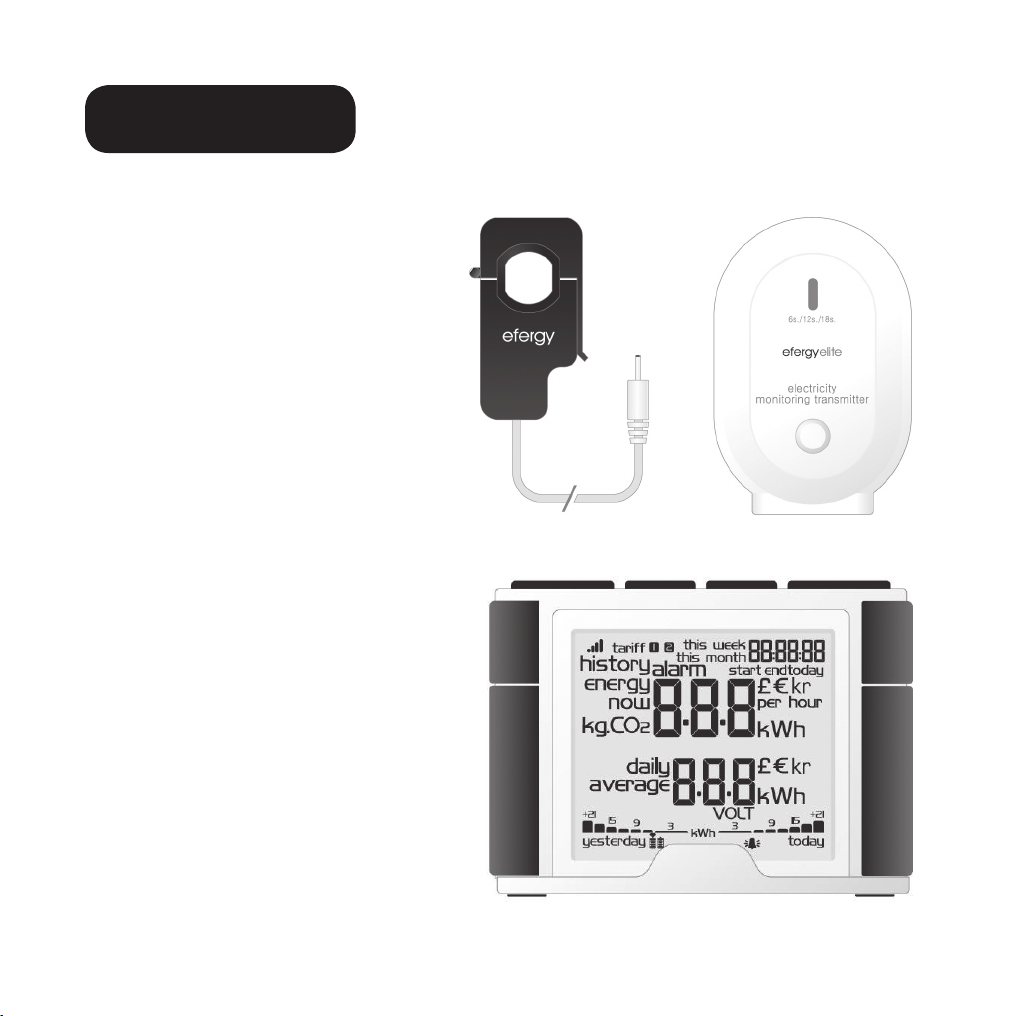
Sensor Transmitter
Display unit
PACKAGE CONTENTS
3 x Sensors (current transformer)
1 x Transmitter
1 x Display unit (receiver)
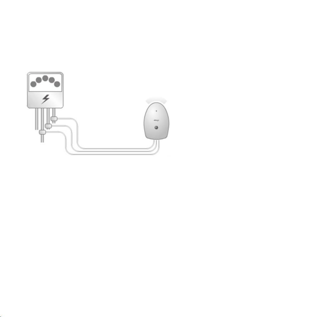
You should clamp the sensors over
the incoming mains power cables
leading into the distribution box. All
power consumed in the household
enter through these cables.
The clip-on sensor senses the current
which passes through these cables.
A reading of the amount of passing
current is then wirelessly sent to the
display unit via the transmitter. The
energy consumption is shown directly
on the display.

Diagram 2
Diagram 1
FINDING THE POWER SUPPLY CABLE FOR YOUR ELECTRICITY METER (UK)
The Efergy energy meter is installed by clamping the sensor clips around the incoming mains
power cables leading to your electricity meter.
FINDING YOUR ELECTRICITY METER
Find out about your electricity meter and check which type you have. It is normally found on an
outer wall, in the garage, in the cellar or in a utility room. If you live in a flat, it may be located near
the entry door, in the stairway, or in the cellar. Make sure the cables exiting the bottom of the
electricity meter are accessible.
Modern offices and flats can have safety panels which protect the cables entering the electricity
meter. If this is your situation, we recommend that you contact a qualified electrician.
FINDING THE POWER SUPPLY CABLE
There are four cables at the bottom of the electricity
meter. The cable on the right (cable 4) is always the
live feed wire (Active phase) from the meter to the
fuse box (se diagram 1).
Certain installations have cables 1 and 2 entirely or par-
tially covered in order to hinder modification or home
installation of cables before the meter (see diagram 2).
Connect the sensor to cable 4 (on the far right)
Meters with dual tariffs (see diagram 3) often have an
extra cable between cable 3 and 4. The extra cable
has a smaller diameter than the other cables and
leads to another electricity meter close by.

7
Diagram 3
Cable 4
Extra cable
Newer installations normally have two
cables on the underside of the meter. One
of the cables is the earth cable and the
other is the feed cable. The sensor should
be clamped around the feed cable (normally
coloured brown).
If you have a 3-phase supply or if you have
an Economy 7 meter you will need additional
sensors. The extra sensors easily connect to
the socket at the base of the transmitter.
N.B. The energy meter comes with 3 sensors.
SAFETY
You should under no circumstances connect a sensor to a cable if any of the cables leading
to the meter is damaged in any way. No cables need to be cut. Do not clip any cables. Do not
break any seals or such on the meter.
Contact your local electricity supplier if you are at all uncertain about connecting the sensor to
the correct cable.

FINDING THE POWER SUPPLY CABLE FOR YOUR ELECTRICITY METER (SE) (NO) (FIN)
The Efergy energy meter is installed by clamping the sensor clips around the incoming mains
power cables leading to your electricity meter.
FINDING YOUR ELECTRICITY METER/DISTRIBUTION BOX
Find out where your meter is located. It is normally found on an outer wall, in the garage, in the
cellar or in a utility room. If you live in a flat, it may be located near the entry door, in the stairway,
or in the cellar. Make sure the cables exiting the bottom of the electricity meter are accessible.
Modern homes and flats can have safety panels which protect the cables entering the meter.
These are often sealed. Under no circumstances should the seals be broken other than by a
qualified electrician. Instead, we recommend that the sensors be installed after the main switch in
your distribution box.
If you still feel unsure as to how to mount the sensor, we recommend that you contact
a qualified electrician.
9
Sensor (3x)
Transmitter
Electricity meter
FINDING THE POWER SUPPLY CABLE
In Sweden, Norway and Finland there are four feed cables entering the electricity meter: 3 live phases
(L1, L2, L3) and 1 Neutral (N), Neutral is normally blue and the live cables are either black or brown.
Cables L1 – L2 – L3 are live and it is these that the sensors should be attached to.
SAFETY
You should under no circumstances connect a sensor to a cable if any of the cables leading
to the meter is damaged in any way. No cables need to be cut. Do not clip any cables. Do not
break any seals or such on the meter.
Contact your local electrical supplier if you are at all uncertain about connecting the sensors to
the correct cable.
INSTALLATION
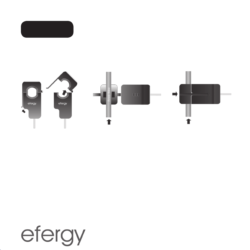
MOUNTING THE SENSORS
The sensors should be clamped onto one (UK) or three (SE) (NO) (FIN) live feed phases. The sen-
sors can be used on cables up to 12 mm in diameter. The sensor must not be mounted with force.
1. Find your live feed cable (UK), cables (SE) (NO) (FIN).
2. Press the release cap upwards to open the sensor.
3. Make sure that you have the correct cable and place the sensor around the cable.
4. Press the sensor together and a click will be heard when the release cap locks.
5. Mount a sensor on the respective live feed cables L1, L2, L3 (SE) (NO) (FIN).
CONNECT THE SENSOR TO THE TRANSMITTER
Plug the sensors into the sockets on the bottom of the transmitter. The sensors/plugs do not
have to be in any particular order.
The sensor senses the current which passes through these cables. A reading of the amount of
passing current is wirelessly sent to the display unit via the transmitter. The energy consumption
is shown directly on the display.
11
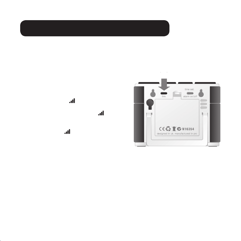
Link
SYNCHRONISING THE TRANSMITTER AND DISPLAY UNIT
1. Start by inserting three AA/LR6 batteries into
the transmitter’s battery compartment, and
three AA/LR6 batteries in the display unit’s bat-
tery compartment.
Tip: If the transmitter is located outdoors, it is
extra important to use good quality batteries.
Use Alkaline or preferably Lithium batteries
which tolerate cold better.
2. Press [Link] on the backside of the display unit.
The transmitter icon will flash for a minute.
3. Press the button on the front of the transmit-
ter once while the transmitter icon flashes.
Wait until the icon stops flashing.
Tip: If synchronisation is successful, the
transmission icon will show on the display.
– – – will show on the displayen
if unsuccessful.
N.B. The preinstalled update interval is six seconds. This means that the transmitter sends
updates every six seconds. It is possible to adjust this interval to 6, 12 or 18 seconds by
depressing the transmission button for two seconds (The LED colour will change).
• Red = 6 s.
• Green = 12 s.
• Orange = 18 s.

Time Set
SETTING THE TIME AND DATE
The energy meter must be programmed with the correct time and date in order to give accurate
information. Setting the time and date:
STEP 1
On the back of the display there is a settings button
[Time set]. Depress this button for two seconds.
The date display will begin to flash.
STEP 2
Set the correct date using the [Bwd] and [Fwd]
buttons. Press [Mode] to confirm and to continue
on to setting the month. Repeat this procedure
to set the year. Press [Mode] to confirm and to
continue with setting the time.
STEP 3
Set the correct hour using the [Bwd] and [Fwd] buttons. Press [Mode] to confirm and to
continue. Repeat this procedure to set the minutes. Press [History] to confirm the setting.

13
History BWD FWD Mode
History BWD FWD Mode
OTHER SETTINGS
The energy meter must be programmed with the correct tariff per kWh in order to give accurate
information. Setting the tariff (valid only if you DO NOT have a dual tariff meter).
N.B. You must be in normal display mode before adjusting any settings. Press [History] the
required number of times until history NO LONGER shows in the display.
Activating the settings mode: Depress [Mode] for two seconds.
N.B. If no button is pushed for 20 seconds the display will go back to normal display mode
without saving any changes.
STEP 1. VOLTAGE
Depress [Mode] for two seconds. 230 will flash (230 V is
preset). Adjust the voltage using [Bwd] and [Fwd] if you
have a different mains voltage. Press [Mode] to confirm
and to continue to the currency setting.
STEP 2. CURRENCY
Set the correct currency (kr, €,or £) using the [Bwd] and
[Fwd] buttons. Press [Mode] to confirm and to continue
to the tariff setting.
History BWD FWD Mode
History BWD FWD Mode
History BWD FWD Mode
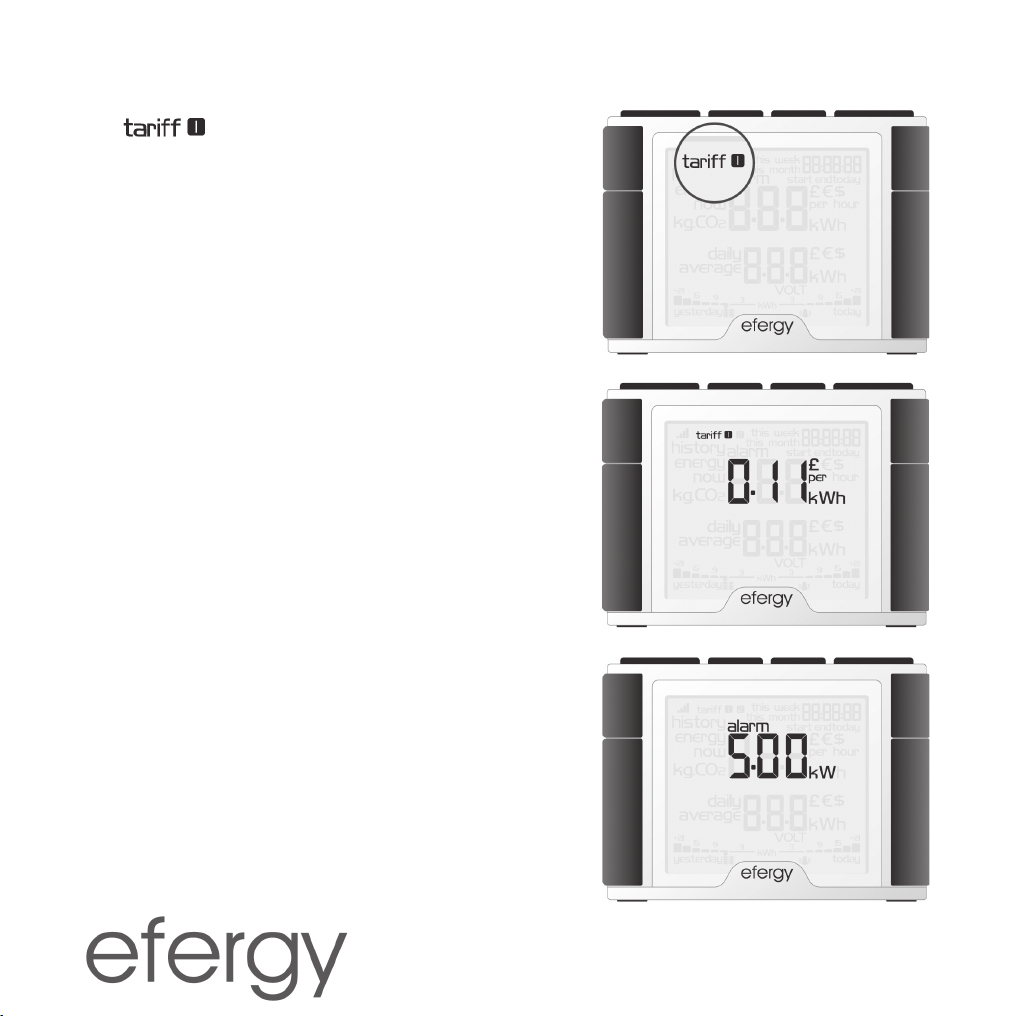
STEP 3. SINGLE TARIFF
The symbol will begin flashing. Press [Mode]
to confirm if you use a single tariff. Refer to section Dual
Tariff if you have an electricity meter for dual tariffs.
Tip: During the entire installation process you may press
[History] to save your settings and return to normal
display mode.
STEP 4. COSTS
Set the correct tariff using the [Bwd] and [Fwd] buttons.
Press [Mode] to confirm and continue.
STEP 5. KG CO2(KG CARBON DIOXIDE PER KWH)
The kg CO2/kWh can be adjusted with the [Bwd] and
[Fwd] buttons. Press [Mode] to confirm and continue on
to setting the alarm.
STEP 6. ALARM
(HIGH-ENERGY CONSUMPTION ALARM)
The preset alarm value is set to 5 kW. If the alarm
feature is activated and you use more than 5 kW the
alarm will sound and a red indicator lamp will light on the
display unit. The alarm activation value can be set using
the [Bwd] and [Fwd] buttons. Press [Mode] to confirm.
Press [Alarm on/off] on the back of the display unit to
activate or deactivate the alarm. Press [History] to exit
the settings mode.
15
History BWD FWD Mode
History BWD FWD Mode
DUAL TARIFF
If you have an electic meter with dual tariffs, you need to program the energy meter for this function.
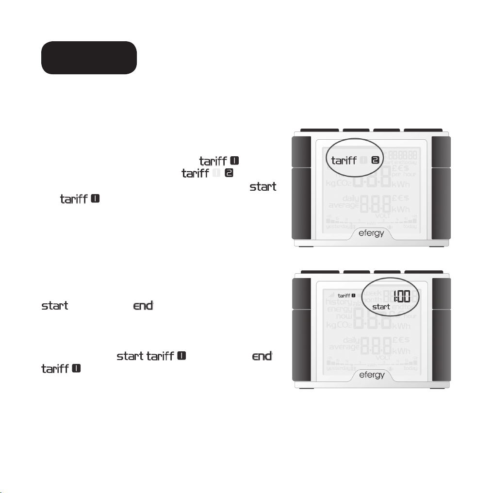
STEP1. ACTIVATING DUAL TARIFFS
Depress [Mode] for two seconds. The value for the set
voltage (230) will begin to flash. Press [Mode] two times
to open the dual tariff settings mode. will flash
twice on the display. Advance to with the
[Bwd] or [Fwd] buttons. Press [Mode] to confirm.
and will begin flashing.
STEP 2. SETTING THE START & STOP TIMES
FOR TARIFF 1
Set the start time for tariff 1 with the [Bwd] or [Fwd]
buttons. First set the start time by setting the hours and
press [Mode] to confirm. Continue setting the minutes
using the same process. Press [Mode] to confirm.
is replaced by on the display. Set the stop
time for tariff 1 using the same process.
Example: You are on an Economy-7 tariff from 01.00
to 08.00. Set the 01.00 and the
08.00. Press [Mode] to confirm. Then set the
currency and tariff per kWh for both tariffs for both day
and night.

History BWD FWD Mode
History BWD FWD Mode
STEP 3. SETTING TARIFF 1
The preset value will begin flashing. Set the present
tariff per kWh with the [Bwd] or [Fwd] buttons. Press
[Mode] to confirm. will begin flashing.
STEP 4. SETTING TARIFF 2
The preset value will begin flashing. Set the present
tariff per kWh with the [Bwd] or [Fwd] buttons. Press
[Mode] to confirm. 230 (the preset voltage) will begin
flashing on the display.
17
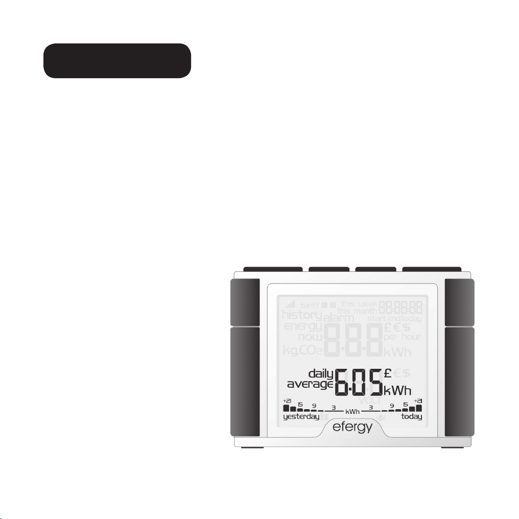
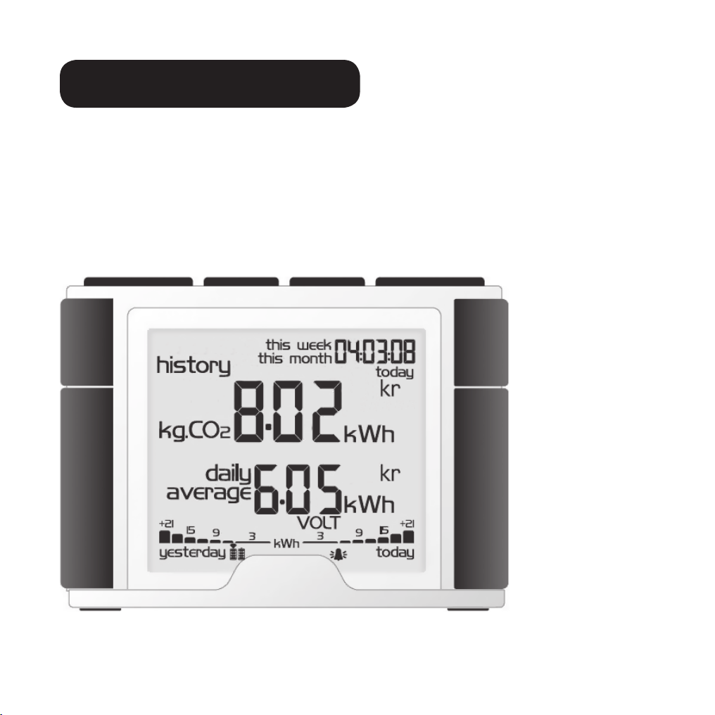
DISPLAY INFORMATION
The energy meter displays information on present, previous and average energy consumption.
PRESENT AVERAGE CONSUMPTION
The display shows average consumption in kWh, cost or carbon dioxide emissions*.
Press [Mode] to switch between displaying kWh, tariff or kg CO2.
* Amount of produced kg CO2used for the production of the electricity consumed.
The amount of CO2produced depends on how your electrical energy is produced e.g. hydro-
electric-, wind-, coal-power, etc. It is up to you to determine and set the CO2per kWh value.
(See Other Settings, Step 5)
GRAPHIC DISPLAY
On the bottom portion of the display
a graphic representation for the
current day and the previous day’s
energy consumption is shown.
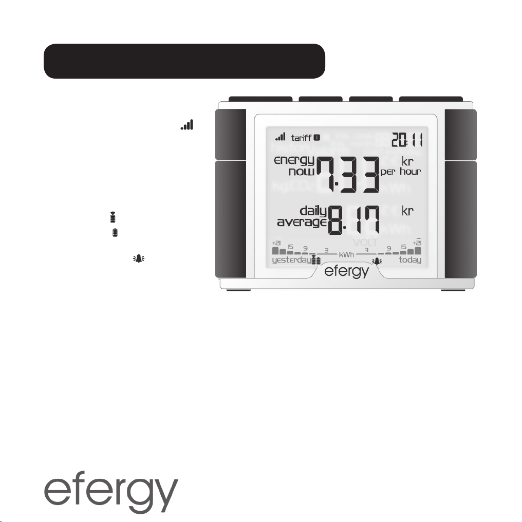
NORMAL DISPLAY OF PRESENT CONSUMPTION
The following is shown on
the display:
1. Transmission strength icon
2. Tariff per hour or present con-
sumption (change settings with
the [Mode] button)
3. Low battery warning:
Transmitter
Display unit
4. Alarm activated:
19
History BWD FWD Mode
PREVIOUS CONSUMPTION DISPLAY
• Press [History] to display previous consumption.
• Press [History] to switch between displays. Current day’s energy consumption – most recent
week – most recent month.
• Switch between day/month with [Bwd] or [Fwd] to compare energy consumption.
• Press [Mode] to switch between displaying kWh- tariff - amount CO2.
TROUBLESHOOTING/FAQ
If I remove the battery, will I lose all my saved data?
No, the information is saved in the internal memory and is not lost when the battery is changed.
How do I reset the display (erase all data and start over)?
Depress [History] and [Mode/set] simultaneously. Clr will show on the display.
N.B. If you reset the energy meter all information on previous consumption is erased.
However, time and date information is saved in the memory.
What is the transmitter’s range?
The range is over 40 metres in a normal home. The 433 MHz frequency is very suitable for this
purpose. With good conditions the signals are able to span up to three floors.
The displayen shows – – –. What does it mean?
Move the display unit closer to the transmitter and press [Link]. If the problem persists, contact
our Customer Services.
Why does the background light come on sometimes?
The background light is timer controlled in order to save the battery. It is only activated at night.
The transmitter and the display unit (receiver) don’t seem to have contact with each
other. What do I do?
Move the display unit closer to the transmitter and press [Link]. If this doesn’t help, try changing
the transmitter batteries. If the problem persists contact our Customer Services.
This manual suits for next models
1
Table of contents
Other Efergy Measuring Instrument manuals


