Data in compliance with EN 61010-1, EN 61326 7KT1 300 7KT1 301
Supply
• Rated control supply voltage UnV 230 230
• Operating range xUn0.8 ... 1.2 0.8 ... 1.2
• Rated frequency Hz 50 50
• Frequency range Hz 45 ... 65 45 ... 65
• Rated power dissipatrion VA <10 <10
Overload capability
•Voltage continuous: phase/phase V 480 480
1 second: phase/phase V 800 800
continuous: phase/N V 276 276
1 second: phase/N V 460 460
• Current continuous A 76 6
0,5 s A – 110
10 ms A 2000 –
Measuring input
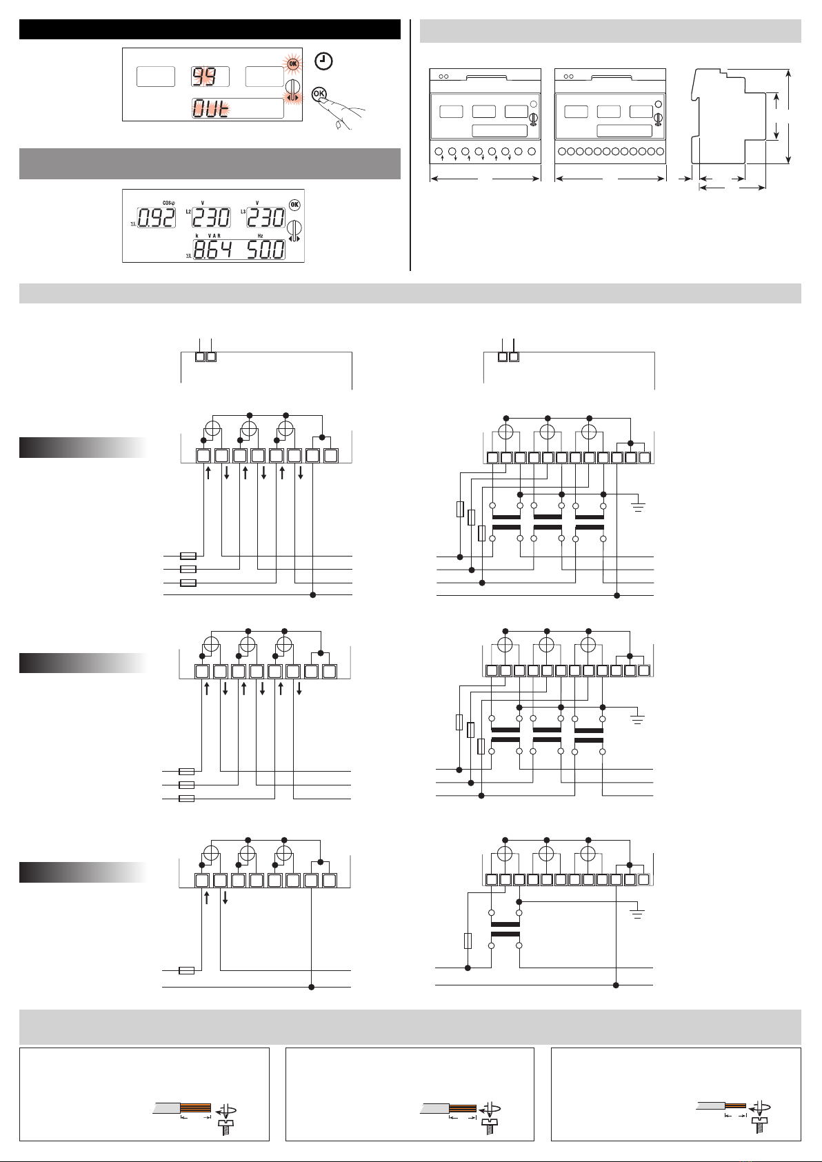
• Type of connection direct transformer .../1 A or .../5A
• Voltage Unphase/phase V 400 400
phase/N V 230 230
• Operating range voltage phase/phase V 87 ... 480 87 ... 480
phase/N V 50 ... 276 50 ... 276
• Current Ib / InA 63 1 or 5
• Operating range current A 0.3 ... 76 0.012 ... 6
•Transformer current primary current of the transformer A – 5 ... 5000
smallest input step A – 5
• Frequency Hz 50 50
• Operating range frequency Hz 45 ... 65 45 ... 65
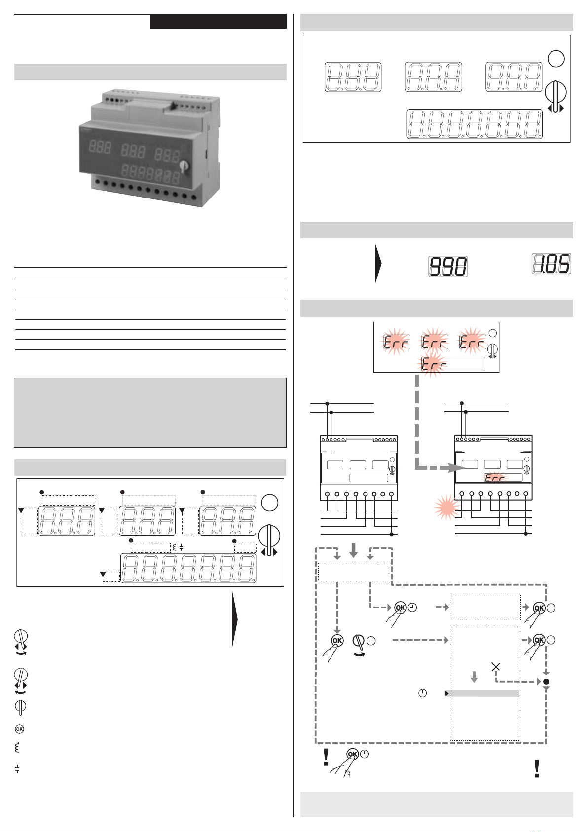
Display
• Connection errors inverted phases Err Err
•Voltage: 3 displays, 3-digit delta L1-L2, L2-L3, L3-L1 V 87 ... 480 87 ... 480
star L1/N - L2/N - L3/N V 50 ... 276 50 ... 276
voltage >480/276 V H H H H H H
voltage <87/50 V – – – – – –
•Current: 3 displays, 3-digit L1 - L2 - L3 A or kA 0.3 ... 76 (0.012 ... 1.2 or 6) x transformer
conversion ratio
for current >76; 1,2 or H H H H H H
6 A x transformer conversion ratio
for current <0,3; 0,012 A 0 0 0 0 0 0
x transformer conversion ratio
• Frequency: 1 display, 3-digit SL Hz 45.0 ... 65.0 45.0 ... 65.0
• Active power: 3 displays, 3-digit or 1 display L1 - L2 - L3; SL W, kW or 0 ... 999 0 ... 999
3 of 7 digits display with floating decimal point MW
• Reactive power: 1 display, 3-digit SL, with capacitative or inductive var, kvar 0 ... 999 0 ... 999
indication: transf. conversion ratio or Mvar
• Apparent power: 3 displays, 3-digit or L1 - L2 - L3; SLVA, kVA 0 ... 999 0 ... 999
1 display, 3-digit display with floating decimal point or MVA
•Cosw:3 displays, 3-digit or L1 - L2 - L3; SL0.01 ... 1.00 0.01 ... 1.00
1 display, 3-digit display with floating decimal point
• Transformer primary current only if set A – 5 ... 5000
• Transformer secondary current only if set A – 1 or 5
• Display period refresh /s 2 2
• Storage of setting EEPROM EEPROM
Measuring accuracy (of nominal values In- Ib- Un)
• Voltage % ±2 ±1 digit ±2 ±1 digit
• Current % ±2 ±1 digit ±2 ±1 digit
•Power output %±2 ... ±4 ± 1 digit ±2 ... ±4 ± 1 digit
• Cosw% ±2 ... ±10 ± 1 digit ±2 ... ±10 ± 1 digit
• Frequency % ±1 ±1 digit ±1 ±1 digit
Safety acc. to EN 61010-1
• Degree of pollution 22
• Overvoltage category II II
•Operational voltage V 600 600
• Test pulse voltage 1,2/50 µs kV 4 4
Terminals
•Main current paths ±screw with mark (Pozidrive) mm PZ2 PZ1
•Power supply and auxiliary blade for slotted screw (Pozidrive) mm 0.8 x 3.5 0.8 x 3.5
• Conductor cross sections-main current paths rigid, max. mm21 x 25 or 2 x 16 1 x 6 or 2 x 4
rigid, min. mm21 x 1.5 1 X 0.95
• Power supply and auxiliary cable section rigid, max. / (min.) mm22.5 / (0.14) 2.5 / (0.14)
flexible with sleeve, max. / (min.) mm21.5 / (0.25) 1.5 / (0.25)
Environmental conditions
• Temperature °C 0 ... +55 0 ... +55
•Relative humidity %<80 <80
• Vibrations sinus-amplitude at 50 Hz mm ±0.25 ±0.25
• Protection class acc. to EN 61010-1 II II
• Degree of protection (terminal area) IP40 (IP20) IP40 (IP20)
- 10 / 12 -
ENGLISH
Technical data
SIEMENS-Multimeter-DIN