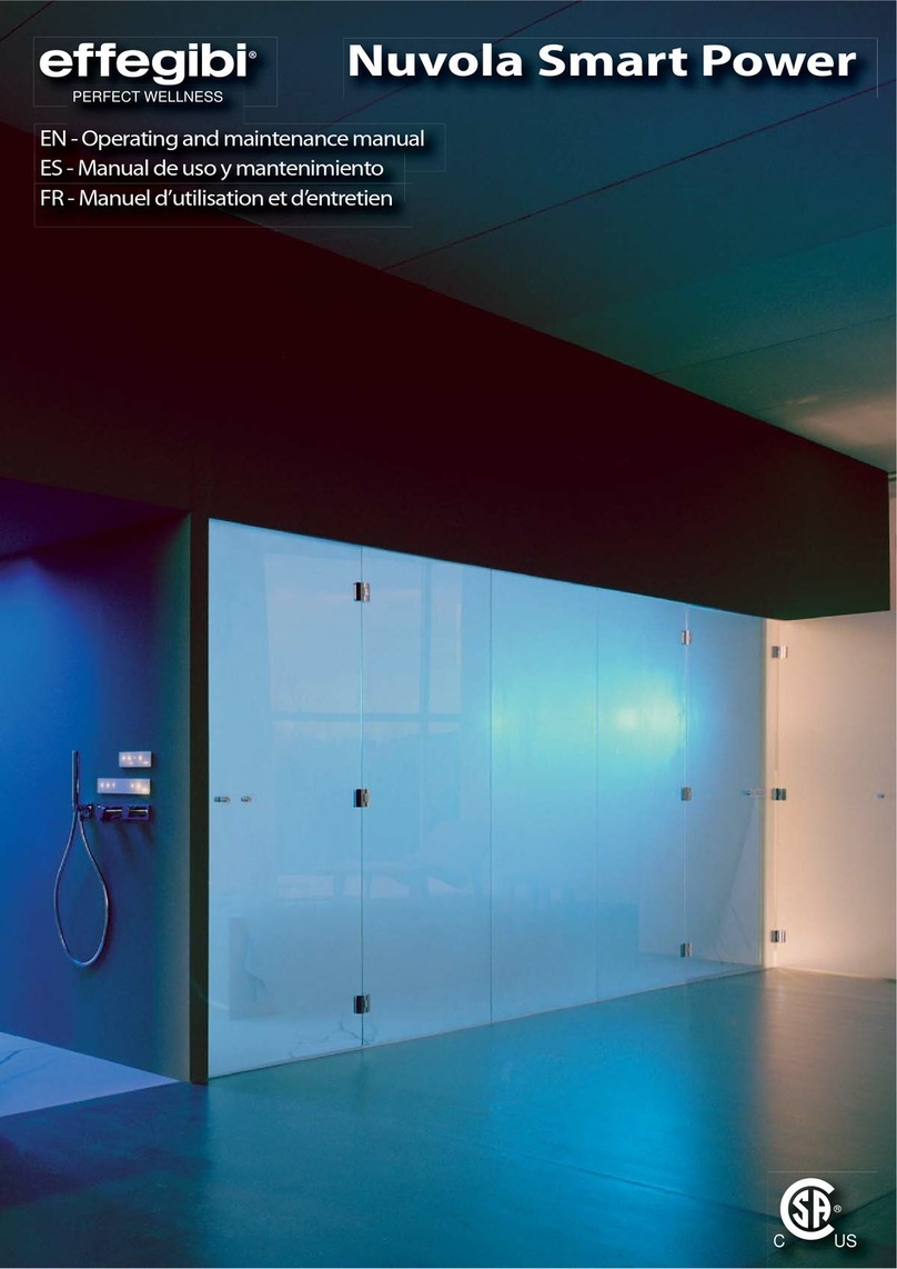
effegibi Effe NUVOLA SMART POWER 110 User manual

1
NUVOLA SMART POWER
110-140-180
Manuale di montaggio
Assembly manual
Manuel de montage
Montageanleitung


NUVOLA SMART POWER 110-140-180
1
Gentile cliente, La ringraziamo per aver scelto un nostro prodotto, EFFEGIBI si augura che
Lei possa rimanere completamente soddisfatto dell’acquisto eettuato. Le ricordiamo
che il presente manuale, deve essere considerato parte integrante della NUVOLA
SMART POWER e deve seguire il percorso di vendita no all’utilizzatore. EFFEGIBI ne
vieta la riproduzione di qualsiasi parte. Ogni NUVOLA SMART POWER, prima di lasciare il
nostro stabilimento, subisce una serie di collaudi e controlli che garantiscono il corretto
funzionamento e l’assoluta adabilità dei suoi dispositivi di sicurezza. Per qualsiasi
informazione e delucidazione potrà sempre rivolgersi ad un nostro concessionario di zona
oppure direttamente alla nostra sede.
IT
Dear Customer, thank you for purchasing an EFFEGIBI NUVOLA SMART POWER. We hope
you will be fully satised with your purchase. Please remember that this manual is an
important document of reference and should be provided by the seller with the NUVOLA
SMART POWER. EFFEGIBI forbids the reproduction of any part of this manual. Each NUVOLA
SMART POWER is checked and tested thoroughly at our premises prior to delivery to
ensure its correct working order and the absolute reliability of its safety devices. Should
you require any further information or clarications please contact your local dealer or
contact our company directly.
EN
Cher client, nous vous remercions d’avoir choisi notre NUVOLA SMART POWER et EFFEGIBI
espère que vous serez entièrement satisfaits de votre achat. Nous vous rappelons que ce
Manuel doit être considéré comme faisant partie intégrante du NUVOLA SMART POWER
et doit suivre le parcours de vente jusqu’à l’utilisateur. EFFEGIBI en interdit la reproduction
complète ou partielle. Chaque NUVOLA SMART POWER, avant de quitter l’usine, subit
une série de tests et de contrôles qui en garantissent le bon fonctionnement et la parfaite
abilité de ses dispositifs de sécurité. Pour toute information et éclaircissement vous
pourrez toujours vous adresser à l’un de nos centres agréés ou directement à notre siège.
FR
SehrgeehrterKunde,wirdankenIhnen,dassSiesichfüreinesunsererProdukteentschieden
haben und hoen, dass Sie mit Ihrem Kauf stets voll zufrieden sein werden. Vergessen
Sie nicht, dass die vorliegende Anleitung, die wesentlicher Bestandteil von NUVOLA
SMART POWER ist, diesem bis hin zum Anwender beizulegen ist. EFFEGIBI verbietet die
diesbezügliche auch nur auszugsweise Vervielfältigung. Jedes NUVOLA SMART POWER
durchläuft vor dem Verlassen unseres Werks eine Reihe von Abnahmeprüfungen und
Kontrollen,welchedieeinwandfreieFunktionstauglichkeitunddieabsoluteZuverlässigkeit
seiner Sicherheitsvorrichtungen garantieren. Für Informationen und Erklärungen können
Sie sich jederzeit an einen unserer Vertragshändler oder direkt an uns wenden.
DE

NUVOLA SMART POWER 110-140-180 2
IT
SOMMARIO
1. SIMBOLOGIA 3
2. AVVERTENZE PRELIMINARI PER INSTALLAZIONE 4
3. MONTAGGIO 7
3.1 DISIMBALLAGGIO 7
3.2 INSTALLAZIONE 7
3.3 CABLAGGIO NUVOLA VERSIONE SENZA ILLUMINAZIONE LED 52
3.4 CABLAGGIO NUVOLA VERSIONE CON ILLUMINAZIONE LED OPTIONAL 53
4. SCHEMA ELETTRICO 54
5. SEGNALAZIONE ERRORI E LORO RISOLUZIONE 56
5.1 ERRORI PRIORITÀ MASSIMA 56
5.2 ERRORI PRIORITÀ ALTA 56
5.3 ERRORI PRIORITÀ MEDIA 56
5.4 ERRORI PRIORITÀ BASSA 57

NUVOLA SMART POWER 110-140-180
3
IT
1. SIMBOLOGIA
Ogni volta che, consultando il manuale, troverete questi simboli, leggete attentamente le frasi riportate perché sono
di fondamentale importanza per un uso corretto della vostro generatore di vapore. Il mancato rispetto di quanto
riportato, potrebbe causare danni alle cose ed alle persone.
PERICOLO-ATTENZIONE
Indica situazioni di grave pericolo che se trascurate possono mettere seriamente a rischio la sicurezza e la salute delle
persone.
CAUTELA-PRECAUZIONE
Indica che è necessario adottare comportamenti adeguati per non incorrere in incidenti e/o provocare danni a cose
e/o persone
DIVIETO
Indica il divieto di eettuare determinate azioni per non incorrere in incidenti e/o provocare danni a cose e/o persone
NOTA
Indica informazioni tecniche da non trascurare e di particolare importanza.

NUVOLA SMART POWER 110-140-180 4
IT
Questo libretto è parte integrante del prodotto: conservarlo con cura in luogo accessibile.
2. AVVERTENZE PRELIMINARI PER INSTALLAZIONE
Tutti i collegamenti devono essere eseguiti da personale qualicato o da un centro assistenza autorizzato in
conformità alle normative locali ed internazionali; CEI64.8 (IEC 60364 – 1). Le predisposizioni elettriche ed idrauliche
devono essere realizzate in maniera corretta, cioè:
-linea idrica dotata di saracinesca di chiusura;
-linea di scarico sifonata;
-linea elettrica dotata di adeguato interruttore magnetotermico e dierenziale come da schema elettrico;
Il collegamento delle tubazioni deve essere eettuato in modo reversibile, cioè deve consentire eventuali rimozioni
del Generatore di vapore dovute per esempio, a manutenzioni straordinarie. Le tubazioni devono essere costituite
solamente da tubi in ottone o in rame
- Installare il generatore di vapore in un ambiente asciutto e ben ventilato. Installarlo in ambienti interni per
evitare congelamenti nei periodi invernali.
- L’accesso al generatore di vapore non deve essere ostruito per facilitare gli interventi di manutenzione.
1 Collegamento dispositivi pannello - Predisporre una guaina elettrica (ø 25 mm) per il collegamento fra il
Generatore ed il pannello Individuare all’interno del vano bagno turco il punto dove posizionare il pannello di
comando e/o gli altri dispositivi, considerando un’altezza di circa 120 cm da terra ed evitando la zona al di sopra dei
diusori di vapore; - Inserire nella guaina il cavo di collegamento (fornito in lunghezza di 8 m); - Siliconare la parte
posteriore del pannello su tutta la circonferenza ed applicarlo sulla parete; - Eettuare il collegamento elettrico al
Generatore in conformità agli schemi elettrici allegati, attraverso i connettori PAN1, PAN2.
2 Collegamento plafoniera d’illuminazione (optional) - Predisporre una guaina elettrica (ø 25 mm) per il
collegamento fra la plafoniera d’illuminazione ed il Generatore; - Eettuare il collegamento elettrico al Generatore
in conformità agli schemi elettrici allegati, attraverso il connettore BUS. - Utilizzare un cavo di collegamento con
caratteristiche adatte al modello di generatore come da tabella pag. 30.
3 Collegamento alla rete elettrica - (230 o 400 Volt 50 Hz ) - Installare sulla linea di alimentazione elettrica,
a monte dell’apparecchio, un interruttore automatico omologato e fusibili di protezione, come indicato negli
schemi elettrici allegati. La distanza minima dei contatti deve essere di 3 mm come indicato nella categoria per
sovratensioni III. - Predisporre un guaina di adeguata sezione. - Prima dell’allacciamento leggere attentamente
i valori sull’etichetta identicativa del generatore, posta all’interno del coperchio e controllare che la tensione
di alimentazione corrisponda alla tensione nominale dell’apparecchiatura. - Collegare per primo il conduttore di
protezione (giallo – verde) - In caso di manutenzione staccare per ultimo il conduttore di protezione (giallo – verde).
Se il cavo di alimentazione è danneggiato, deve essere sostituito dal produttore, dal suo servizio assistenza o da
personale qualicato al ne di evitare rischi.

NUVOLA SMART POWER 110-140-180
5
IT
4 Condotta di Vapore - Prima di procedere con l’installazione della condotta vapore è necessario determinare la
posizione del diusore.
Idiusori devono essereinstallati nellaparteinferiore diuna parete internadel vano bagnoturco rispettando
una distanza dal pavimento di 25 cm.
Nell’installazione della condotta vapore non superare mai una lunghezza complessiva di 5m.
Non installare una saracinesca nella condotta di vapore. Il usso del vapore deve essere libero e la condotta
esente da sifoni avendo cura che la tubazione abbia una naturale pendenza dal generatore verso il locale bagno
turco così da permettere lo scarico della condensa.
- Utilizzare tubi in rame o ottone con lunghezza massima di 5 m.
- Coibentare bene i tubi di condotta del vapore.
- Non posizionare il diusore del vapore vicino alle postazioni di seduta; il vapore può provocare ustioni.
- Sigillare i raccordi delle tubazioni con idoneo materiale per prevenire eventuali fuoriuscite di vapore.
- Non ostruire la condotta o i fori di uscita del vapore.
5 Alimentazione acqua - Si consiglia di installare un rubinetto di intercettazione (non fornito) per poter chiudere
l’acqua durante le operazioni di manutenzione dell’apparecchio, Alimentare il generatore solo con acqua fredda (Max
25 °C). Se nell’acqua sono presenti particelle solide, si consiglia l’installazione di un ltro,
Se l’acqua di alimentazione del generatore è “dura” o “mediamente dura” (>30 °f) si consiglia l’installazione
di un decalcicatore per salvaguardare la caldaia vapore oppure eettuare una decalcicazione più frequente.
Senza decalcicatore la caldaia del Generatore subisce un deterioramento precoce.
La pressione dell’acqua in entrata non deve superare gli 8 bar (800 kPa) max. Per un utilizzo ottimale, la
pressione dell’acqua dovrebbe essere compresa fra 1.5 ÷ 2 bar (150 ÷ 200 kPa) max; Predisporre la tubazione
a lo parete con terminale lettato ½” F
6 Scarico acqua - (Ø 32)
La tubazione di drenaggio, oltre a resistere ad alte temperature (MAX 100°C), deve garantire il corretto
deusso dell’acqua; pertanto si consiglia una pendenza verso il basso di circa 5%. Collegare la valvola di scarico
direttamente alla tubazione di drenaggio senza interporre saracinesche di chiusura, evitate sifonature o restringimenti
di diametro. Il diametro minimo della tubazione è ø 32. Predisporre la tubazione con terminale ø 32 femmina già
sifonata;
All’interno del Generatore avviene l’ebollizione dell’acqua con trasformazione in vapore, senza aggiunta di alcun
tipo di sostanza. L’acqua di drenaggio, quindi, contiene le medesime sostanze disciolte nell’acqua di alimento ma in
quantità maggiore, a seconda dalla concentrazione nell’acqua di alimento e dai cicli di drenaggio impostati, e può
raggiungere una temperatura di 100 °C. Utilizzare per la linea di scarico tubature resistenti alle alte temperature.
L’acqua di drenaggio, non essendo tossica, può venire drenata tranquillamente nel sistema di raccolta delle acque
bianche.

NUVOLA SMART POWER 110-140-180 6
IT
- Il Bagno Turco deve essere chiuso da muri, sotto e porta adeguata per evitare fuoriuscite di vapore.
- La porta deve essere adatta all’ambiente Bagno Turco con adeguate guarnizioni per evitare la fuoriuscita del
vapore
- I materiali usati per il pavimento devono avere trattamento antiscivolo adeguato.. In mancanza aggiungere
strisce di materiale antiscivolo apposito per evitare cadute all’interno del vano.
- Sul pavimento deve essere predisposto uno scarico per il deuire dell’acqua.
- Pareti e sotto devono essere rivestiti con materiali resistenti all’acqua e non corrosivi, si possono utilizzare
piastrelle, marmo opportunamente trattato o altri materiali non porosi.
- Non installare impianti di riscaldamento, condizionamento o ventilazione all’interno della Steam Room.
- In caso siano presenti nestre nel vano Bagno Turco accertarsi che siano dotate di vetro doppio per evitare
dispersioni di calore.

NUVOLA SMART POWER 110-140-180
7
IT
3. MONTAGGIO
3.1 DISIMBALLAGGIO
Aprire tutti i cartoni avendo cura di non danneggiarne il contenuto.
Dopo aver rimosso l’imballo, vericare la completezza e l’integrità dei materiali.
In caso di danni imputabili al trasporto, è necessario che ciò sia segnalato al trasportatore nei termini legali per non
perdere il diritto all’indennizzo da parte della compagnia di assicurazione.
3.2 INSTALLAZIONE
- Il Generatore di vapore deve essere installato e posizionato in apposito vano tecnico apribile mediante
arnese o utility room accessibile mediante chiave.
- Il Generatore di vapore deve essere installato in ambiente asciutto, che non superi la temperatura di 40°C.
INSTALLAZIONE A MURO
L’apparecchiatura viene appesa per mezzo delle stae di ssaggio in dotazione da applicare alla scocca del generatore.
Dierenti tipi di muro richiedono dierenti tipi di tasselli di ssaggio. Utilizzare quello più idoneo in funzione del tipo
di muro presente. L’ingresso e l’uscita dei cablaggi elettrici ed idrici sono situate nella parte laterale sinistra del
generatore di vapore. Identiche per tutte le versioni di potenza. L’aerazione è garantita dalle aperture situate sul
sulla parte posteriore e sul fondo del generatore di vapore.
INSTALLAZIONE IN APPOGGIO SU VANO CHIUSO E SEMICHIUSO
Montaggio in appoggio su una supercie. È necessario rispettare le misure minime del vano che devono maggiori
o uguali a 100 mm di distanza tra il generatore di vapore e il fondo del vano e tra generatore di vapore e lati interni
del vano. L’ingresso e l’uscita dei cablaggi elettrici ed idrici sono situate nella parte laterale sinistra del generatore
di vapore.
Identiche per tutte le versioni di potenza. L’aerazione è garantita dalle aperture situate sul sulla parte posteriore e
sul fondo del generatore di vapore.

NUVOLA SMART POWER 110-140-180 8
EN
SUMMARY
1. SYMBOLS 9
2. PRELIMINARY WARNINGS FOR INSTALLATION 10
3. ASSEMBLY 13
3.1 UNPACKING 13
3.2 INSTALLATION 13
3.3 WIRING THE NUVOLA VERSION WITHOUT LED LIGHTING 52
3.4 WIRING THE NUVOLA VERSION WITH LED LIGHTING OPTIONAL 53
4. SCHEMA ELETTRICO 54
5. ERROR REPORTING AND THEIR RESOLUTION 60
5.1 MAXIMUM PRIORITY ERRORS 60
5.2 HIGH PRIORITY ERRORS 60
5.3 AVERAGE PRIORITY ERRORS 60
5.4 LOW PRIORITY ERRORS 61

NUVOLA SMART POWER 110-140-180
9
EN
1. SYMBOLS
Each time that, you nd these symbols when consulting the manual, carefully read the sentences reported because
they are of fundamental importance for a correct use of your steam generator. Failure to observe the above, could
cause damage to things and people.
DANGER-ATTENTION
This indicates situations of serious danger that if neglected can seriously put the health and safety of persons at risk.
CAUTION-PRECAUTION
This indicates that it is necessary to adopt appropriate conduct to avoid accidents and/or cause damage to things
and/or people
PROHIBITION
This indicates that it is prohibited to perform certain actions in order to avoid accidents and/or causing damage to
things and/or people
NOTE
This identies technical information that should not be overlooked and is of particular importance.

NUVOLA SMART POWER 110-140-180 10
EN
This manual is an integral part of the product and should be kept in a safe, accessible place.
2. PRELIMINARY WARNINGS FOR INSTALLATION
All connections must be performed by qualied personnel or an authorised service centre in compliance with local
regulations and international standards; CEI64.8 (IEC 60364 - 1). Electrical and hydraulic preinstallations must be
performed correctly, i.e.:
- the water line must be equipped with closing gate valve;
- the discharge line must be siphoned;
- the electric line must be equipped with adequate magnetothermal and dierential switch as shown in the
wiring diagram;
The pipes must be connected in a reversible manner, i.e. allowing the removal of the steam generator e.g. for
extraordinary maintenance. The pipes must only consist of tubes made of brass or copper
- Install the steam generator in a dry and well ventilated area. Install it in internal areas to avoid freezing in
winter periods.
- Access to the steam generator must not be blocked for easier servicing.
1 Connection of panel devices - Provide an electrical sheath (ø 25mm) for the connection between the Generator and
the panel Identify the best point to place the control panel and/or other devices within the Turkish bath compartment,
considering a height of approximately 120 cm from the ground and avoiding the area above the steam diusers; -
Insert the connecting cable into the sheath (supplied in 8m lengths); - Siliconize the rear part of the panel on the
whole circumference and apply it to the wall; - Perform the electrical connection to the generator in accordance with
the attached wiring diagrams, through connectors PAN1, PAN2.
2 Connecting the light tting (optional) - Prepare an electrical sheath (ø 25 mm) for the connection between the
light tting and the generator; - Perform the electrical connection to the generator in accordance with the attached
wiring diagrams, through connector BUS. - Use a jumper cable with characteristics suitable for the generator model
as per Table page 30.
3 Connection to the electrical network - (230 or 400Volts 50 Hz) - Install an approved circuit breaker and protection
fuses on the electrical power supply line, upstream of the appliance, as specied in the attached wiring diagrams. The
minimum distance of the contacts must be 3 mm as indicated in the category for overvoltages III. - Provide a sheath
of suitable section. - Before connecting, carefully read the values on the identication label of the generator, placed
inside the cover and check that the supply voltage matches the voltage rating of the equipment. - First connect the
protection conductor (yellow - green) - In the event of maintenance remove the protective conductor last (yellow -
green).
If the power cable is damaged it must be replaced by the manufacturer, by its assistance service or by qualied
personnel to ensure any risks are avoided.

NUVOLA SMART POWER 110-140-180
11
EN
4 Steam Duct - Before proceeding with the installation of the steam duct, itis necessary to determine the position of
the diuser.
The diusers must be installed in the lower part of an inner wall of the Turkish bath compartment, at a 25 cm
distance from the oor.
The steam pipes must not exceed a total length of 5 m.
Do not install a gate in the steam duct. The steam ow must be free and the duct must be free from siphons
taking care to ensure the pipe has a natural slope from the generator to the Turkish bath compartment to allow for
discharging the condensate.
- Use copper or brass pipes with maximum length 5m.
- Insulate the steam ducts properly.
- Do not place the steam diuser close to the seating stations; steam can cause burns.
- Seal the pipe unions with suitable material so as to prevent any leakage of steam.
- Do not block the steam duct or outlet holes.
5 Water supply - It is advisable to install a cut-o cock (not supplied) to be able to close the water during the
maintenance operations of the appliance, Power the generator only with cold water (Max 25°C). If solid particles are
present in the water, we recommend installing a lter
If the feed water of the generator is “hard” or “averagely hard” (>30 °f) we recommend installing a water
softener to safeguard the steam boiler or carry out more frequent decalcication. The Generator boiler is
subject premature deterioration without decalcier.
The pressure of the incoming water must not exceed 8 bar (800 kPa) max. For optimal use, the water pressure
should be between 1.5 ÷ 2 bar (150 ÷ 200 kPa) max; Fix the pipe to the wall with the threaded terminal ½”F
6 Water discharge - (Ø 32)
In addition to resisting high temperatures (max 100°C), the drain line must ensure correct outow of water;
therefore a downward slope of about 5% is recommended. Connect the exhaust valve directly to the drain line
without interposing closing gates, avoid siphoning or narrowing of the diameter. The minimum diameter of the pipe
is ø 32. Prepare the pipe with ø 32 already siphoned female end;
The water is boiled with transformation into steam inside the generator, without the addition of any type of substance.
Thus, the drainage water contains the same substances dissolved in the feed water but in greater quantity, depending
on the concentration in the feed water and the set drainage cycles, and can reach a temperature of 100°C. Use high
temperature resistant pipes for the discharge line.
Since it is not toxic, it can be drained in the drainage system for white waters.

NUVOLA SMART POWER 110-140-180 12
EN
- The Turkish Bath must be closed by walls, ceiling and adequate door to prevent the outow of steam.
- The door must be suited to theTurkish Bath compartment with suitable seals to prevent the outow of steam
- The materials used for the oor must have adequate non-slip treatment. In its absence, add strips of non-slip
material suitable to prevent falls inside the compartment.
- A discharge for the water ow must be providded on the oor.
- The walls and ceiling must be coated with water resistant and non-corrosive materials, you can use tiles,
suitably treated marble or other non-porous materials.
- Do not install heating, air-conditioning or ventilation systems inside the Steam Room.
- In case there are windows in the Turkish Bath compartment make sure that they are double glazed to avoid
heat dispersion.

NUVOLA SMART POWER 110-140-180
13
EN
3. ASSEMBLY
3.1 UNPACKING
Open all cartons taking care not to damage the contents.
After having removed the package, check the completeness and integrity of the materials.
In the case of damage attributable to transport, it is necessary for this to be reported to the transporter within the
legal terms in order to avoid losing the right to compensation provided by the insurance company.
3.2 INSTALLATION
- The steam generator must be installed and positioned in a suitable technical compartment that can be
opened by means of the tool or utility room accessible using a key.
- The steam generator must be installed in a dry area, which not exceeding the temperature of 40°C.
WALL INSTALLATION
The appliance is hung by xing brackets supplied to be applied to the generator body. Dierent types of walls require
dierent types of xing. Use the most suitable according to the type of wall present. The inlet and outlet of the
electrical wiring and water are located in the left side of the steam generator. Identical for all power supply versions.
Aeration is guaranteed by ports located on the back and on the bottom of the steam generator.
INSTALLATION ON SUPPORTING CLOSED AND PARTIALLY CLOSED COMPARTMENT
Assembly on supporting surface. It is necessary to respect the minimum measures of the compartment which must
be equal to or larger than 100mm distance between the steam generator and the bottom of the compartment and
between the steam generator and the internal sides of the compartment. The inlet and outlet of the electrical wiring
and water are located in the left side of the steam generator.
Identical for all power supply versions. Aeration is guaranteed by ports located on the back and on the bottom of the
steam generator.

NUVOLA SMART POWER 110-140-180 14
FR
SOMMAIRE
1. SYMBOLES UTILISES 15
2. INDICATIONS PRELIMINAIRES D’INSTALLATION 16
3. ASSEMBLAGE 19
3.1 RETRAIT DE L’EMBALLAGE 19
3.2 INSTALLATION 19
3.3 CÂBLAGE NUVOLA VERSION SANS ÉCLAIRAGE LED 52
3.4 CÂBLAGE NUVOLA VERSION AVEC ÉCLAIRAGE LED EN OPTION 53
4. SCHÉMA ÉLECTRIQUE 54
5. SIGNALISATION D’ERREURS ET SOLUTIONS 64
5.1 ERREURS DE PRIORITE MAX 64
5.2 ERREURS DE PRIORITE HAUTE 64
5.3 ERREURS DE PRIORITE MOYENNE 64
5.4 ERREURS DE PRIORITE BASSE 65

NUVOLA SMART POWER 110-140-180
15
FR
1. SYMBOLES UTILISES
Lire attentivement le contenu relatif chaque fois qu’on trouve ces symboles dans le livret, puisqu’il s’agit d’informations
fondamentales pour utiliser correctement le générateur de vapeur. Le non respect de ces indications pourrait causer
des lésions et endommager des pièces.
DANGER – ATTENTION
Ce symbole indique des situations extrêmement dangereuses qui ne doivent pas être négligées, ce qui compromettrait
sérieusement la santé et la sécurité des personnes.
PRUDENCE - PRECAUTION
Ce symbole indique qu’il est nécessaire de se conduire adéquatement pour éviter tout accident et/ou des dommages
ou des lésions.
INTERDICTION
Ce symbole indique qu’il est nécessaire d’eectuer des actions spéciques pour éviter tout accident et/ou des
dommages ou des lésions.
REMARQUE
Ce symbole indique des informations techniques plutôt importantes qui ne doivent pas être négligées.

NUVOLA SMART POWER 110-140-180 16
FR
Ce manuel fait partie intégrante du produit : le conserver dans un endroit accessible.
2. INDICATIONS PRELIMINAIRES D’INSTALLATION
Tous les raccordements doivent être exécutés par du personnel qualié ou le service après-vente agréé, conformément
aux normes locales et internationales ; CEI 64.8 (IEC 60364 - 1). Préparer de façon convenable les branchements
électriques et les raccordements hydrauliques, à savoir :
- ligne hydraulique équipée de vanne d’arrêt,
- ligne d’évacuation avec siphon,
- ligne électrique pourvue de disjoncteur magnétothermique et diérentiel convenable (selon les indications
du schéma électrique).
Le raccordement des tuyaux doit être réversible, à savoir il doit permettre l’enlèvement éventuel du générateur de
vapeur pour eecteur, par exemple, des opérations de maintenance non périodique. Les tuyaux doivent être réalisés
exclusivement en laiton ou en cuivre.
- Installer le générateur de vapeur dans une zone sèche et bien ventilée. L’installer à l’intérieur, pour éviter le
gel pendant l’hiver.
- L’accès au générateur de vapeur ne doit pas être obstrué, ce qui empêcherait l’exécution des opérations de
maintenance.
1 Connexion des dispositifs panneau - Préparer une gaine électrique (ø 25 mm) pour connecter le générateur au
panneau. Dans la pièce du bain turc, localiser la zone d’installation du panneau de commande et/ou des autres
dispositifs, en respectant une hauteur de 120 cm environ du sol et en évitant la zone au-dessus des diuseurs de
vapeur. - Insérer dans la gaine le câble de connexion (fourni en standard, 8 m de long). - Siliconer la partie arrière
du panneau, sur la circonférence complète et sur la paroi. - Brancher le générateur conformément aux schémas
électriques fournis, moyennant les connecteurs PAN1, PAN2.
2 Connexion du plafonnier d’éclairage (en option) - Préparer une gaine électrique (ø 25 mm) pour connecter le
plafonnier d’éclairage au générateur. - Brancher le générateur conformément aux schémas électriques fournis par
le connecteur BUS - Utiliser un câble de connexion dont les caractéristiques doivent être conformes au modèle de
générateur, conformément aux indications du tableau p. 30.
3 Connexion au réseau électrique - (230 ou 400 V, 50 Hz) - Sur la ligne d’alimentation électrique, en amont de
l’appareil, installer un disjoncteur homologué et des fusibles de protection, conformément aux indications des
schémas électriques fournis. La distance minimale des contacts doit être de 3 mm, selon les indications pour la
catégorie de surtension III. - Préparer une gaine de section appropriée. - Avant le branchement, lire attentivement les
valeurs sur l’étiquette d’identication du générateur, appliquée à l’intérieur du couvercle, et s’assurer que la tension
d’alimentation correspond à la tension nominale de l’appareil. - Connecter le premier conducteur de protection
(jaune - vert). - Lors des activités de maintenance, débrancher en dernier le conducteur de protection (jaune - vert).
Si le câble d’alimentation est endommagé, il doit être remplacé par le producteur, par son service d’assistance ou par
du personnel qualié an d’éviter tous risques.

NUVOLA SMART POWER 110-140-180
17
FR
4 Conduite de vapeur – Avant d’installer la conduite de vapeur, décider la position du diuseur.
Les diuseurs doivent être installés dans la partie inférieure d’une paroi interne de la pièce du bain turc, à une
distance du sol de 25 cm.
En installant la conduite de vapeur, ne jamais dépasser une longueur totale de 5m.
Ne pas installer de vannes d’arrêt dans la conduite de vapeur. Le débit de la vapeur doit être régulier et la conduite
doit être dépourvue de siphons ; en plus, le tuyau doit présenter une pente naturelle du générateur vers le bain turc,
ce qui permet de vidanger correctement l’eau de condensation.
- Utiliser des tuyaux en cuivre ou en laiton (5 m de long au maximum).
- Isoler correctement les tuyaux de vapeur.
- Ne pas positionner le diuseur de vapeur près des banquettes : la vapeur peut causer des brûlures.
- Sceller les raccords des tuyaux par du matériau convenable, pour prévenir toute sortie éventuelle de vapeur.
- Ne pas obstruer la conduite ni les trous de sortie de la vapeur.
5 Alimentation en eau – Il est conseillé d’installer une soupape d’arrêt (non fournie) pour arrêter le débit d’eau
pendant les opérations de maintenance de l’appareil. N’alimenter le générateur qu’en utilisant de l’eau froide (25°C au
maximum). Si l’eau contient des particules solides, il est conseillé d’installer un ltre.
Si l’eau d’alimentation du générateur est“dure”ou “moyennement dure” (>30 °f), il est conseillé d’installer un
décalcicateur pour sauvegarder la chaudière à vapeur ou décalcier plus fréquemment. En l’absence d’un
décalcicateur, la chaudière du générateur pourrait s’endommager rapidement.
La pression de l’eau à l’entrée ne doit pas dépasser 8 bars (800 kPa) au maximum. Pour un emploi optimal, la
pression de l’eau devrait être comprise entre 1,5 et 2 bars (150 ÷ 200 kPa) au maximum. Préparer la conduite
au niveau de la paroi, en utilisant un raccord leté ½”femelle.
6 Vidange de l’eau - (Ø 32)
En plus que résister aux hautes températures (100°C au maximum), le tuyau de drainage doit garantir un
écoulement correct de l’eau ; par conséquent, il est conseillé de préparer une pente en bas de 5% environ.
Raccorder la soupape de vidange directement au tuyau de drainage, sans utiliser de vannes d’arrêt ou de siphons ; ne
pas réduire le diamètre. Le diamètre minimum du tuyau est ø 32. Préparer un tuyau en utilisant un raccord femelle ø
32 déjà équipé de siphon.
L’ébullition de l’eau et sa transformation en vapeur se fait à l’intérieur du générateur, sans l’ajout de substances. Par
conséquent, l’eau de drainage contient les mêmes substances dissoutes dans l’eau d’alimentation, mais en quantité
supérieure, selon la concentration dans l’eau d’alimentation et les cycles de drainage établis, et peut atteindre une
température de 100°C. Pour la ligne d’évacuation, utiliser des tuyaux résistants aux hautes températures.
Étant donné qu’elle n’est pas toxique, l’eau de drainage peut être évacuée sans problème vers le système de
récupération des eaux blanches.

NUVOLA SMART POWER 110-140-180 18
FR
- Le bain turc doit être fermé avec des parois, un plafond et une porte adéquats, an d’éviter toute perte de
vapeur.
- La porte doit être conforme à l’endroit du bain turc et équipée de joints convenables pour éviter toute perte
de vapeur.
- Les matériaux utilisés pour le sol doivent être traités avec une substance antiglisse adéquate. Autrement,
ajouter des bandes antiglisse spéciques pour éviter toute chute éventuelle.
- Sur le sol, préparer un point d’écoulement convenable de l’eau.
- Les parois et le plafond doivent être revêtus de matériaux résistants à l’eau et anticorrosifs (tels que les
carreaux ou les marbres, traités de façon convenable, ou d’autres matériaux non poreux).
- Ne pas installer d’installations de chauage, de climatisation ou de ventilation à l’intérieur du hammam.
- En présence de fenêtres dans la pièce du bain turc, s’assurer qu’elles sont équipées de double vitrage pour
éviter les dispersions de chaleur.
This manual suits for next models
2
Table of contents
Other effegibi Iron manuals
