EFFIKAL RVGP-KS-BKF Series User manual
1
EFFIKAL INTERNATIONAL INC.
143 NORTHPOINTE DRIVE
ORION, MICHIGAN 48359
(248) 370-9554
DO NOT TURN DAMPER MANUALLY WITH OR WITHOUT ELECTRICAL
POWER OR MOTOR DAMAGE WILL OCCUR, USE THE SERVICE SWITCH.
LIMITED 5 YEAR WARRANTY ON MOTORIZED CONTROLLER
LIMITED 25 YEAR WARRANTY AVAILABLE TO HOMEOWNER
SPECIFICATIONS, INSTALLATION INSTRUCTIONS, AND TROUBLESHOOTING GUIDE FOR EFFIKAL AUTOMATIC
VENT DAMPER RVGP-KS-BKF SERIES FOR USE ON LISTED GAS FIRED BOILERS WITH A DRAFT HOOD.
TO THE USER
For continued safe operation, the appliance-device combination should be inspected annually by a qualified service agency. It is
recommended that the homeowner examine all flue product carry areas of the appliance, its vent system, and the damper device,
with particular attention given to deterioration from corrosion or other sources. This examination should be performed prior to and
during each heating season. Also use Exhibit A, page 2 and Final Inspection, page 7.
CAUTION
Install this plug in hole in damper blade on all boilers
equipped with intermittent ignition systems only. DO
NOT install this plug on standing pilot systems. Failure
to follow these instructions can cause nuisance odor
problems and minor property damage due to moisture if
ignored.
RVGP-KS 3/00 ©
•The Effikal RVGP Series Automatic Damper must be
installed by a qualified installing agency in accordance
with the manufacturer’s installation instructions. The
definition of a Qualified Installation Agency is: any indi-
vidual, firm, corporation or company which either in
person or through a representative is engaged in, and
is responsible for, the installation and operation of gas
appliances and automatic vent damper devices, who
is experienced in such work, familiar with all the pre-
cautions required, and has complied with all the
requirements of the authority having jurisdiction. The
qualified installer shall fill in the installer’s name,
address and installation date on the label attached to
the vent damper device.
•Do not negate the action of any existing safety or
operational controls.
•When servicing controls, all wires must be LABELED
prior to disconnection. Wiring errors can cause
improper and dangerous operation.
•Device must be installed by a qualified installer, in
compliance with local codes or the National Fuel Gas
Code (ANSI Z223.1 NFPA 54) and the National
Electric Code (ANSI C1-NFPA 70).
•Device conforms to ANSI Z21.66 and ADDENDA.
CGA and AGA design certified.
•Use only with a listed gas fired boiler equipped with a
draft hood, the outlet area of which is not greater than
the inlet area of the device.
•Install after the boiler draft hood, as close to the draft
hood as practicable, and without modification to the
draft hood or the vent damper.
•Locate in a venting system or section of a venting sys-
tem so that it services only the single boiler for which it
is intended.
•Aminimum clearance of 6 inches (153mm) between
the damper device and combustible construction must
be maintained and that there be provisions for access
and service of the damper device.
•Position indicator and service switch must be accessi-
ble to the user.
•The installer must fill in the label on the side of the
controller cover.
•This device must be installed only on a boiler connect-
ed to a factory built chimney or vent complying with a
recognized standard, or a masonry or concrete chim-
ney lined with a lining material acceptable to the
authority having jurisdiction.
•This vent damper device shall not be installed on an
appliance with an automatic valve having a manual
opener unless the manual opener has been rendered
in-operative or the automatic valve has been replaced
with a redundant automatic valve not equipped with a
manual opener.
WARNING
READ INSTRUCTION BOOKLET CAREFULLY AND COMPLETELY BEFORE PROCEEDING WITH THE INSTALLATION.
NOT FOR
RETROFIT
IN CANADA

2
IMPORTANT
THE STEP-BY-STEP INSPECTION AND INSTALLATION PROCEDURES
AS SPECIFIED IN EXHIBITS A AND B MUST BE FOLLOWED.
THE QUALIFIED INSTALLER MUST FILL IN LABEL ON THE SIDE OF THE CONTROLLER.
EXHIBIT A
PROCEDURE FOR SAFETY INSPECTION OF AN EXISTING APPLIANCE INSTALLATION
The following procedure is intended as a guide to aid in determining that an appliance is properly installed and is in a safe condition for continuing use.
This procedure is predicated on a central furnace, boiler and water heater installations, and it should be recognized that generalized procedures cannot anticipate
all situations. Accordingly, in some cases deviation from this procedure may be necessary to determine safe operation of the equipment.
a. This procedure shall be performed prior to installation of the automatic vent damper device.
b. If it is determined there is a condition which could result in unsafe operation, the appliance should be shut off and the owner advised of the unsafe condi-
tion. Do not install the automatic vent damper device until the unsafe condition has been corrected.
The following steps are to be followed in making the safety inspection:
1. Conduct a gas leakage test of the appliance piping and control system downstream of the valve in the supply line to the appliance.
2. Visually inspect the venting system for proper size, horizontal pitch and vent termination, and determine there is no blockage or restriction, leakage, corro-
sion and other deficiencies which could cause an unsafe condition.
3. Determine that the chimney or vent is acceptable to the authority having jurisdiction.
4. Shut off all gas to the appliance and shut off any other fuel-gas burning appliance within the same room. Use shutoff valve in the supply line to each appli-
ance.
5. Inspect burners and crossovers for blockage and corrosion.
6. Applicable only to furnaces — inspect heat exchanger for cracks, openings or excessive corrosion.
7. Applicable only to boilers — inspect for evidence of water or combustion product leaks.
8. Insofar as is practical, close all building doors and windows and all doors between the space in which the appliance is located and other spaces of the build-
ing. Turn on clothes dryers. Turn on any exhaust fans, such as range hoods and bathroom exhausts, so they will operate at maximum speed. Do not operate
a summer exhaust fan. Close fireplace dampers, If, after completing Steps 9 through 14, it is believed sufficient combustion air is not available, refer to local
codes, or in the absence of local codes, to the NATIONAL FUEL GAS CODE, ANSI Z223.1—1996 (NFPA 54), for guidance.
9. Place in operation the appliance being inspected. Follow the lighting instructions. Adjust thermostat so appliance will operate continuously.
10. Determine that the pilot(s), when provided, is burning properly and that main burner ignition is satisfactory by interrupting and reestablishing the electrical
supply to the appliance in any convenient manner.
If the appliance is equipped with a continuous pilot(s), test the pilot safety device(s) to determine if it is operating properly by extinguishing the pilot(s)
when the main burner(s) is off and determining, after 3 minutes, that the main burner gas does not flow upon a call for heat.
If the appliance is not provided with a pilot(s), test for proper operation of the ignition system in accordance with the appliance manufacturer’s lighting and
operating instructions.
11. (a) Visually determine that main burner gas is burning properly: i.e., no floating, lifting or flashback. Adjust the primary air shutter(s) as required.
(b) If the appliance is equipped with high and low flame controlling or flame modulation, check for proper main burner operation at low flame.
12. Test for spillage at the draft hood relief opening after 5 minutes of main burner operation. Use the flame of a match or candle, or smoke from a cigarette,
cigar or pipe.
13. Turn on all other fuel-burning appliances within the same room so they will operate at their full inputs. Follow lighting instructions for each appliance.
14. Repeat Steps 11 and 12 on the appliance being inspected.
15. Return doors, windows, exhaust fans, fireplace dampers and any other fuel-gas burning appliances to their previous conditions of use.
16. Applicable only to furnaces — Check both the limit control and the fan control for proper operation. Limit control operation can be checked by blocking the
circulating air inlet or temporarily disconnecting the electrical supply to the blower motor and determining that the limit control acts to shut off the main
burner gas.
17. Applicable only to boilers —
(a) Determine that the water pumps are in operating condition.
(b) Test low water cutoffs, automatic feed controls, pressure, and temperature limit controls, and relief valves in accordance with the manufacturer’s rec-
ommendations to determine they are in operating condition.
EXHIBIT B
PROCEDURE FOR INSTALLING ELECTRICALLY OPERATED AUTOMATIC VENT DAMPER DEVICES ON EXISTING APPLIANCES
This procedure is intended as a guide to aid in safely installing an electrically operated automatic vent damper device on an existing appliance.
This procedure is based on the assumption that the history of the specific appliance has been one of safe and satisfactory operation.
This procedure is predicated on central furnace, boiler and water heater installations, and it should be recognized that generalized procedures cannot
anticipate all situations. Accordingly, in some cases deviation from this procedure may be necessary to determine safe operation of the equipment.
The following steps are to be followed in making the modifications:
1. Perform a safety inspection of the existing appliance installation. See Exhibit A for the recommended procedure for such a safety inspection.
2. Shut off all gas and electricity to appliance. To shut off gas use the shutoff valve in the supply line to the appliance.
3. Install the automatic vent damper device in strict accordance with the manufacturer’s installation instructions. Make certain the device is not located
in that portion of the venting system which serves any appliance other than the one for which the damper is installed.
4. Make certain wiring connections are tight and wires are positioned and secured so they will not be able to contact high temperature locations.
5. When an additional automatic valve has been incorporated or an existing gas control replaced, conduct a gas leakage test of the appliance piping
and control system downstream of the shut off valve in the supply line to the appliance.
6. Visually inspect the modified venting system for proper horizontal pitch.
7. (a) The damper must be in full open position before the gas valve(s) opens.
(b) The damper must remain in the full open position while the gas valve(s) is open.
(c) The gas valve(s) must be closed before the damper begins its return to the closed position.
(d) The damper shall remain in the closed position during the off cycle of the appliance.
8. Determine the amperage draw of the gas control circuit and damper device.
(a) Check appliance transformer for adequate capacity.
(b) Check heat anticipator in comfort thermostat to determine it is properly adjusted.
9. Sequence the appliance through at least three normal operating cycles.
10. Insofar as is practical, close all building doors and windows and all doors between the space in which the appliance is located and other spaces of
the building. Turn on clothes dryers. Turn on any exhaust fans, such as range hoods and bathroom exhausts, so they will operate at maximum
speed. Do not operate a summer exhaust fan. Close fireplace dampers.
11. Place appliance in operation. Follow the lighting instructions. Adjust thermostat so appliance will operate continuously.
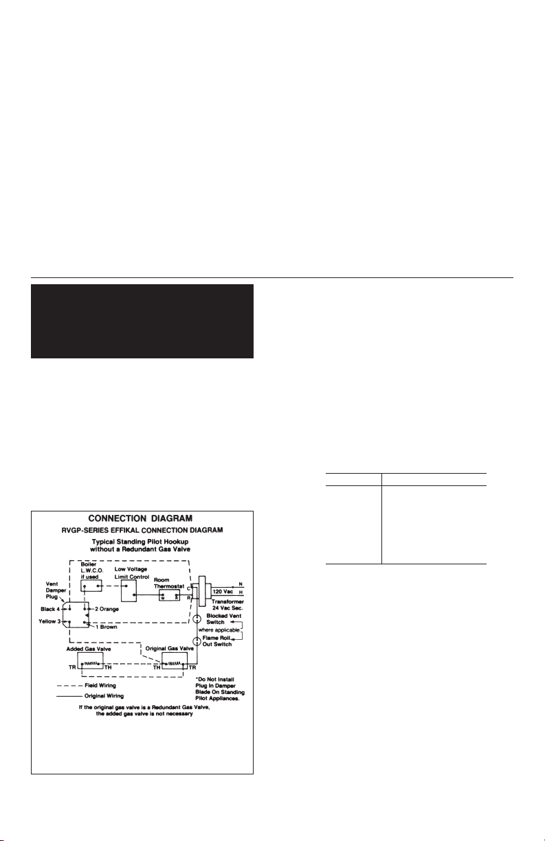
TO INSTALL AN ADDITIONAL GAS VALVE:
a. Shut off the gas and electricity to the gas burner (use the manual
shut off valve in the supply line to the appliance).
b. Locate a position in the supply line between the appliance auto-
matic gas valve and the burner.
c. Both gas valves must terminate the main gas supply to the burn-
er(s). Both gas valves must be piped in series and wired in paral-
lel. See Connection Diagram below.
d. Install an approved appropriately sized single function automatic
gas valve in this location downstream of the existing automatic
gas valve. (Follow the valve manufacturers instructions for flow
directions and position).
e. Restore gas line supply, conduct a leak test on the gas piping and
control system downstream of the appliance shut off valve.
I. INTRODUCTION The Effikal RVGP Series automatic vent damper
was developed to increase the efficiency of boilers by reducing stand-
by losses from the boiler and the conditioned air space. The damper
closes the chimney vent when the burner is off and fully opens it
before the burner is on. The concept is similar to the opening and
closing of a fireplace damper, except the operation is completely auto-
matic. Interlocks have been added, which prevents burner operation
unless the damper is in an open position. A closed damper substan-
tially reduces standby losses on boilers.
II. DESCRIPTION A closed damper prevents residual heat in the boiler
from being drawn up the chimney vent by the chimney’s natural draft.
A closed damper will also prevent conditioned air from being pulled
through the draft hood and up the chimney by the same stack effect, if
it is located within the conditioned space.
When heat is required, the damper rotates to the open position before
the burner circuit is energized. If the damper does not rotate to the
open position, the burner circuit will not be energized. When properly
installed, the electrical circuits in this product are designed not to
override the existing limit and safety controls of the boiler.
III. GENERAL INFORMATION Damper vane and sectional material is
made of stainless steel. Shipping Weight w/Metal Shield Harness.
IV. ELECTRICAL
(MINIMUM WIRING REQUIREMENTS) .........24 VAC, 18 Gauge, 105 C
(THERMOSTAT HEAT ANTICIPATION) ................0.1A PLUS CURRENT
DRAW FOR CONTROL CIRCUIT
(POWER DRAW REQUIREMENT) .......3W AT 24 VAC WHEN OPENING
OR CLOSING
(TIMING) ..........................................................OPENS IN 15 SECONDS
CLOSES IN 15 SECONDS
(CHARACTERISTICS) ......................................................POWER OPEN
POWER CLOSE
V. FEATURES
•SERVICE SWITCH — ELIMINATES NUISANCE CALL BACKS
•FIVE YEAR LIMITED WARRANTY ON MOTORIZED CONTROLLER
FROM DATE OF INSTALLATION.
•25 YEAR LIMITED WARRANTY ON MOTORIZED CONTROLLER
AVAILABLE.
•REDUNDANT INTERLOCK SWITCHES.
•POWER OPEN, POWER CLOSE; EXTENDS PRODUCT LIFE. SELF
CLEANING ACTION.
•24V OPERATION FOR EASY, LOW-COST WIRING.
•SUPPLIED WIRING HARNESS IS COMPATIBLE WITH MANUFAC-
TURERS RECEPTACLE CONFIGURATION.
3
Vent Size RVGP-KS-BKF
43lbs. 6.4 oz.
53lbs. 8.4 oz.
63lbs. 14.4 oz.
74lbs. 6.7 oz.
85lbs. 3.8 oz.
98lbs. 1.5 oz.
10 8 lbs. 12.4 oz.
12 9 lbs. 9.1 oz.
248-370-9554
NOTE: TERMINALS 1, 2 and 3 must be the same polarity
*Add point .1 to Heat Anticipator for vent damper, plus what
is in the circuit.
12. Test for spillage at the draft hood relief opening after 5 minutes of main burner operation. Use the flame of a match or candle, or smoke from a ciga-
rette, cigar or pipe.
13. (a) Visually determine that main burner gas is burning properly: i.e., no floating, lifting or flashback. Adjust the primary air shutter(s) as required.
(b) If the appliance is equipped with high and low flame controlling or flame modulation, check for proper main burner operation at low flame.
14. Determine that the pilot(s), when provided, is burning properly and that main burner ignition is satisfactorily by interrupting and reestablishing the
electrical supply to the appliance in any convenient manner.
If the appliance is equipped with a continuous pilot(s), test the pilot safety device(s) to determine if it is operating properly by extinguishing the pilot(s)
when the main burner(s) is off and determining, after 3 minutes, that the main burner gas does not flow upon or call for heat.
If the appliance is not provided with a pilot(s), test for proper operation of the ignition system in accordance with the appliance manufacturer’s lighting
and operating instructions.
15. Applicable only to furnaces — Check both the limit control and the fan control for proper operation. Limit control operation can be checked by
blocking the circulating air inlet or temporarily disconnecting the electrical supply to the blower motor and determining that the limit control acts to
shut off the main burner gas.
16. Applicable only to boilers —
(a) Determine that the water pumps are in operating condition.
(b) Test low water cutoffs, automatic feed controls, pressure and temperature limit controls, and relief valves in accordance with the manufacturer’s
recommendations to determine they are in operating condition.
17. Label the damper device with information as to:
(a) Name of qualified agency responsible for damper installation.
(b) Date of installation.
For continued safe operation, the homeowner should check all flue product carrying areas of the appliance, its vent system, and the damper device at
least once a year.
Particular attention should be given to the replacement of parts deteriorated by corrosion or other sources. Such replacement must be done by a
qualified installing agency, who shall carry out an annual inspection of the appliance-device combination.
Determine if the appliance has a redundant gas
valve. If it has a redundant gas valve proceed
to install the damper assembly.
WARNING: If the appliance does not have a
redundant gas valve install an additional gas
valve or a redundant gas valve.

4
THE DAMPER MUST BE IN THE OPEN POSITION
BEFORE COMBUSTION TAKES PLACE.
THE DAMPER MUST BE IN THE OPEN POSITION WHEN
THE APPLIANCE MAIN BURNER(S) IS OPERATING.
THE GAS VALVE(S) MUST BE CLOSED BEFORE THE
DAMPER BEGINS ITS RETURN TO THE CLOSED POSI-
TION.
FIGURE 1
INSTALL THE VENT DAMPER TO SERVICE ONLY THE SINGLE
BOILER FOR WHICH IT IS INTENDED. IF IMPROPERLY INSTALLED,
A HAZARDOUS CONDITION, SUCH AS AN EXPLOSION OR CARBON
MONOXIDE POISONING COULD RESULT.
CAUTION: DO NOT INSTALL THE VENT DAMPERS WITHIN 6 IN.
(153mm) OF COMBUSTIBLE MATERIAL.
UNPACKING INSTRUCTIONS
The Effikal RVGP-Series Automatic Gas Vent Damper is
packaged in a single carton containing a stainless steel pipe
assembly, a knock out plug, a motorized controller and
instruction booklet. Inspect for damage prior to the installation.
A wiring harness is required for the installation.
A. The harness may already be attached to the motorized controller per
the boiler manufacturer’s request.
B. The harness may already be attached to the boiler.
C. The harness may be packaged with the vent damper but not attached to
the motorized controller per the boiler manufacturer’s request.
D. A harness may need to be purchased.
EXPLANATION OF MODEL NUMBERS
R=REDUNDANT
V=VALVE
G=GAS
P=PLUG IN AT DAMPER
A=ADAPTER PLATE WITH COUPLING
NUMBER = VENT PIPE SIZE
B=BRUSH THAT PROVIDES A TIGHT SEAL
K=KNOCKOUT FOR STANDING PILOT
F=FLAT ROD IN PIPE ASSEMBLY
KS = CIRCUIT BOARD MODEL
CAUTION
HOW TO INSTALL KNOCKOUT PLUG IN DAMPER BLADE ON GAS FIRED BOILERS
(INTERMITTENT IGNITION SYSTEMS ONLY.)
DO NOT INSTALL KNOCKOUT ON STANDING PILOT SYSTEMS
DO NOT TURN DAMPER MANUALLY – MOTOR DAM-
AGE WILL OCCUR. USE THE SERVICE SWITCH
(SEE FIGURE 6).
The hole in the damper blade provides the minimum vent area required by code for continuous pilot systems. Failure to follow these
instructions can cause nuisance odor problems and minor property damage due to moisture if ignored.
BOILER
*STANDOFF
BRACKET
YES NO
WATER
HEATER
CHIMNEY
ADD .1 TO THE HEAT ANTICIPATOR OF THE ROOM
THERMOSTAT PLUS CURRENT DRAW FOR CONTROL
MODULE.
TYPE A
(CUT-OUT VIEW)
TYPE B
DAMPER BLADE PLACE THE KNOCKOUT
TABS IN THE HOLE
OF THE DAMPER BLADE
HOLD THE KNOCKOUT
AND FOLD THE
FOUR TABS OVER
AB C
1. Remove 2 washers, 1 roundhead slotted
machine screw, and 1 8-32 kep nut from
plastic bag.
2. Place the machine screw through 1 washer.
3. Place damper assembly horizontally.
4. With one hand take the washer and machine
screw and come in from one side of the pipe
assembly UNDER the damper blade.
5. Push the machine screw up through the knock-
out opening.
6. With the other hand take the washer and kep
nut and enter from the opposite side of the
pipe assembly.
7. Place the washer over the machine screw.
8. Put kep nut onto machine screw and hand
tighten.
9. Make sure the knockout opening is totally
covered.
10. Tighten with pliers, adjustable wrench, or
11/32 wrench.

5
HOW TO AVOID NUISANCE NO HEAT CALLS
A. Do not turn damper manually or motor damage will occur. Use the service switch. (See fig. 6)
B. Do not pull on the motorized controller or twist to locate the damper assembly.
C. If self tapping screws are not sharp enough to penetrate the stainless steel pipe assembly, it may be necessary to drill 3 holes
120 degrees apart at the inlet and outlet of the pipe assembly. This should avoid egg shaping the pipe assembly. (See Fig. 3 & 7)
TO INSTALL THE DAMPER ASSEMBLY
DISCONNECT POWER SUPPLY TO PREVENT ELECTRICAL SHOCK OR EQUIPMENT DAMAGE.
Installer, do not egg shape the pipe during this installation or the shafts from the con-
troller to the pipe will not line up properly. A pipe forced out of round is not covered
under our 5 year warranty program. See figure 3.
Install the damper device after the appliance drafthood, as close to the draft hood as practical, and without modification of either the
draft hood or the vent damper device.
Locate a position in the vent pipe between the drafthood and the chimney for the damper assembly. The vent damper device must
be located in a venting system so that it serves only the single appliance for which it is installed (see Figure 1).
To be used only with an appliance bearing a marking showing the make and
model of the device. Canadian Requirement.
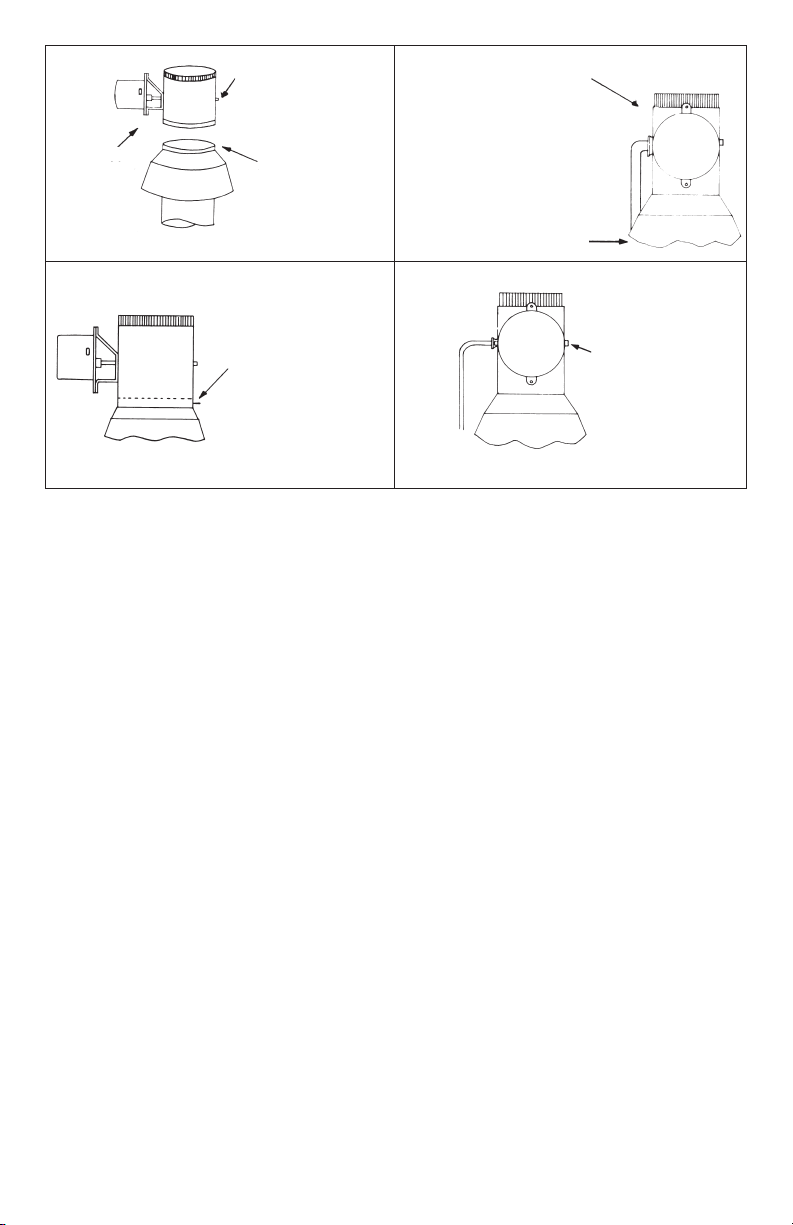
INSTALLING THE VENT DAMPER IN HORIZONTAL AND VERTICAL VENTS:
For vertical vent damper installation, mount the vent damper in any position.
For horizontal vent damper installation, mount the vent damper motorized controller to either side of the vent. See Figure 2.
The vent damper device shall be connected to a chimney or vent complying with a recognized standard, or a masonry or concrete
chimney lined with a lining material acceptable to the enforcing authority.
A minimum clearance of 6 inches (153 mm) between the device and combustible construction must be maintained and that there be
provisions for access and service of the damper device.
To avoid nuisance odor problems, obtain the most radical pitch to the chimney as possible. Remove any appropriate section from
the female end of the vent pipe and reinstall vent pipe and damper assembly. For dimensional data, see Figure 4.
The damper device must be installed in the vent pipe with the
crimped end and directional arrow pointed toward the
chimney, the damper position indicator visible and the
controller unit accessible for wiring. See Figure 5.
The motorized controller is premounted to the stainless steel
pipe assembly. Make sure the controller is secured to the
pipe assembly. The flat rod must be engaged into the slot of
the CAM. This slot protrudes through the base plate of the
controller. See Figures 3 & 7.
The vent damper position indicator is located on the stainless
steel pipe assembly. This is opposite the motorized
controller. The device is equipped with a service switch for
placing the damper in the open position. The service switch is
recessed into the cap of the motorized controller. See Figure
6. It has been appropriately marked hold “open” or
“automatic.” The position indicator and service switch must
be accessible to the user.
Secure the damper assembly at each end to the vent pipe
with three 1/2” sheet metal screws or pop rivets spaced
around the circumference of the vent pipe. If necessary,
provide a suitable hanger to support the damper assembly
independent of the venting system. See Figure 7.
FIGURE 3
BINDING MAY OCCUR
IF THE PIPE BECOMES
EGG-SHAPED.
NUISANCE NO HEAT
CALL MAY OCCUR.
FIGURE 2
CONTROLLER MOUNTING POSITIONS
WHEN INSTALLED IN HORIZONTAL VENT
RVGP-KS-BKF
Top View
CAUTION!
CAUTION
WARNING!
DON NOT PULL ON CONTROLLER
TO POSITION DAMPER OR
‘BINDING MAY OCCUR
DISENGAUGEMENT
MAY OCCUR IF
THE PIPE ASSEMBLY
BECOMES EGG-SHAPED.
1:00 O’clock
Mountng
Range
5:00 O’clock
11:00 O’clock
Avoids excessive heat
Mountng
Range
Avoids condensation
7:00 O’clock

6
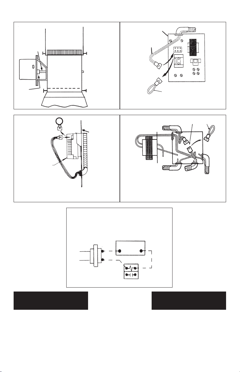
PLUG IN APPLICATIONS:
For plug in applications, locate the vent damper receptacle
on the appliance per the manufacturers instructions and
follow accordingly. For additional plug in connections see
Figure 8, 9, & 10.
When the harness is not attached to the motorized
controller. The harness must be routed through the conduit
bracket. Place the harness receptacle into the damper
plug. Then securely fasten the harness to the conduit
bracket. See Figure 6.
The RVGP-KS series damper must be electrically
connected with all automatic gas valves in the system.
Ensure all connections are tight and that wires cannot
touch hot surfaces. If necessary, use standoff brackets.
See Figure 1.
When the harness is used the jumper must be removed
from the receptacle before the harness plug can be
connected to the appliance.
Once the vent damper is plugged into the control system
and operated through one complete cycle, the control
circuit will operate only when the vent damper is in the
control circuit. Plug in type controls with internal fuses.
All electrical work and material used in the installation shall
be in accordance with local electrical codes in absence of
codes consult the National Electrical Code.
To protect the thermostat heat anticipator turn off the
appliance power supply before proceeding with the wiring.
MICROPROCESSOR THERMOSTATS:
An isolation relay is required when a microprocessor based
thermostat is connected electrically to the vent damper.
This primarily occurs with steam boilers and forced air
furnaces. When the vent damper is energized to open a
voltage drop occurs for 15 seconds which does not allow
the thermostat to rob power to maintain the program.
Thermostat battery life is reduced. When the battery runs
down, erratic cycling may occur. For typical hook up of an
isolation relay, see Figure 11.
The vent damper operates on 24 VAC Systems only. Do
not install if the system operates off 120 VAC or
millivoltage to avoid possible damage to the system and
system shut down.
Do not use the Effikal Dampers with Honeywell L8148 or
L8124 with man/auto switch because the switch can
override the safety interlocks in the system wiring, causing
a hazardous condition.
All wiring from the EFFIKAL RVGP-Series gas vent
damper controller shall be routed clear of mechanical injury
and high temperature locations as directly as possible
along building construction or the gas fuel line to the gas
burner controls. Secure with insulated staples, wire ties,
stand off brackets or tape as required. Make sure all the
wiring connections are neat and tight, and done in a
workmanlike manner.
FIGURE 5
FIGURE 6
FIGURE 4 CAUTION
WIRING
CAUTION
WARNING
EFFIKAL
RVGP-KS
Controller
Pipe
Assembly
D
A
C
E
B
DIM. A
TUBE SIZE
DIM. B
LENGTH
DIM. C
TOTAL HEIGHT
DIM. D DIM. E
4” 6” 95⁄8”15/16” 43⁄4”
5” 6” 105⁄8”15/16” 43⁄4”
6” 61⁄2”11
5⁄8”1
1⁄8”5
1⁄4”
7” 7-1/16” 125⁄8”1
3⁄8”5
3⁄4”
8” 8-1/16” 135⁄8”1
7⁄8”6-13/16”
9” 101⁄8”14
5⁄8”2
7⁄8”8
7⁄8”
10” 121⁄8”15
5⁄8”3
7⁄8”10
7⁄8”
12” 121⁄8”17
5⁄8”3
7⁄8”10
7⁄8”
FLUE GAS
FLOW DIRECTION
ARROW POINTS UP
MOUNT VENT
DAMPER OVER
DRAFTHOOD
MAKE SURE
MOTOR IS
LOCATED SO
THAT WIRE
HARNESS WILL
REACH APPLIANCE
RECEPTACLE
SERVICE SWITCH
MUST BE TO THE
CORRECT POSITION
FOR AUTOMATIC
OPERATION
AUTOMATIC
OPERATION
OR
HOLD
OPEN
RVGP-KS-BKF
ATTACH
HARNESS TO
CONDUIT
BRACKET
7
FIGURE 7
SECURE WITH
POP RIVETS
OR SCREWS
3 IN EACH
JOINT 120°
APART
FIGURE 8
INTERMITTENT CIRCULATION VENT
DAMPER CONNECTIONS
FIGURE 11
FIGURE 9
OUTSIDE
BOILER
JACKET
PANEL
ELECTRONIC
IGNITION VENT DAMPER CONNECTIONS
FIGURE 10
JUNCTION BOX CONNECTION -
CONTINUOUS OR GRAVITY
CIRCULATION WITH VENT DAMPER
FINAL INSPECTION
The service switch must be in the automatic position. See Figure 6.
Check the operation of the automatic damper 3 times with the boiler operating controls for proper sequence.
The damper must be in the open position before combustion takes place.
The damper must be in the open position when the appliance main burner(s) is operating.
The gas valve(s) must be closed before the damper begins its return to the closed position.
PERFORM TEST PROCEDURE OF EXHIBITS A & B.
WARNING WARNING
FLAT ROD
CAM JUMPER
(REMOVE AND DISCARD WHEN
CONNECTING VENT DAMPER)
L8148E OR L8124E
CONTROL
WIRING
HARNESS
IGNITION
MODULE
CONNECT
HARNESS
REMOVE
PLUG
TO CIRCULATOR
(IF USED)
TO CONTROL
TO GAS
VALVE
REMOVE
PLUG
CONNECT
HARNESS
TO DAMPER
DRY CONTACTS ACTS AS THERMOSTAT
ISOLATION
RELAY
MICROPROCESSOR THERMOSTAT
Typical Hookup
Isolation Relay
24 VAC
TRANSFORMER
W
R
R
C

8
NOTICE TO CONTRACTOR
UPON COMPLETION OF THE EFFIKAL DAMPER INSTALLATION, FILL IN THE
INFORMATION INDICATED BELOW AND LEAVE THIS INSTRUCTION BOOKLET
WITH THE HOMEOWNER.
INSTALLER: ____________________________________________________________
ADDRESS: _____________________________________________________________
PHONE NUMBER: _______________________________________________________
DATE INSTALLED:_______________________________________________________
DAMPER SERIAL NO.:____________________________________________________
122222222223
4 5
4 5
4 5
4 5
4 5
4 5
4 5
4 5
4 5
4 5
4 5
677777777778
• SEE AVAILABLE 25 YEAR WARRANTY ON FOLLOWING PAGE •
LIMITED WARRANTY
EFFIKAL
Effikal International Inc. will repair or replace, free of charge, any of its
motorized controllers which fail within five (5) years from date of original
installation due to a result of faulty design, workmanship or materials. Effikal
International Inc. will not be responsible for labor or service charges inciden-
tal to the removal and replacement of a defective part. Replacements for
material claimed defective are subject to adjustment after material claimed
defective has been returned to Effikal International Inc. by prepaid trans-
portation for inspection. This warranty does not extend to failures occurring
because of damage incurred in or resulting from shipment or accident in
transit, improper installation, alteration, abnormal use, defective repair, or
exposure to abnormal environment. There are no warranties of either mer-
chantability or fitness for a particular purpose, Effikal International Inc
assumes no liability for consequential damages, loss of goodwill, production,
income or labor in replacing defective products, which result from use or
misuse of its products.
This warranty gives you specific legal rights, and you may also have other
rights which vary from state to state. Some states do not allow limitations on
how long an implied warranty lasts, and some states do not allow the exclu-
sion or limitation of incidental or consequential damages, so the above limi-
tations or exclusions may not apply to you.
Inquiries to the manufacturer concerning this warranty should be directed to:
EFFIKAL INTERNATIONAL INC.
143 NORTHPOINTE DRIVE, ORION, MICHIGAN 48359
ATTN: RETURN GOODS/WARRANTY DEPARTMENT
For prompt and efficient response, the Effikal owner should apply for war-
ranty claims via written notice, to the representative or dealer selling the
product.

9
Registration #____________
Name ___________________________________________________________
Street ___________________________________________________________
City ________________________________ State _________ ZIP _________
Phone __(_____) _____________________
Type of heating appliance: (Check one)
■■Hot Water Boiler ■■Steam Boiler ■■Furnace
Effikal Information
Number of Effikals Series No.(s)
Installed at this address _____________ (outside cap)_______________
Installed by _______________________________________________________
Address__________________________________________________________
Phone __(_____) _____________________
I am interested in the “25 YEAR-LIMITED-LIFETIME WARRANTY.”
I understand that the $100.00 registration fee is per installed Effikal unit.
This is good only for original homeowner (purchaser) at the original address of
installation.
a $100.00 registration fee per Effikal unit installed is enclosed:
■■YES ■■NO
Signature ______________________________________ Date ____________
NOTE: Only the HOMEOWNER may apply for this guarantee.
LIMITED WARRANTY
Effikal International Inc. will replace, free of charge, any of its controllers which fail within twenty-five (25) years from date of original installation due to a result of faulty design, workmanship or materials. Effikal
International Inc. will not be responsible for labor or service charges incidental to the removal and replacement of a defective part. Replacements for material claimed defective are subject to adjustment after
material claimed defective has been returned to Effikal by prepaid transportation for inspection. This warranty does not extend to failures occurring because of damage incurred in or resulting from shipment or
accident in transit, improper installation, alteration, abnormal use, defective repair, or exposure to abnormal environment. There are no warranties of either merchantability or fitness for a particular purpose,
Effikal International Inc. assumes no liability for consequential damages, loss of goodwill, production, income or labor in replacing defective products, which result from use or misuse of its products.
This warranty gives you specific legal rights, and you may also have other rights which vary from state to state. Some states do not allow limitations on how long an implied warranty lasts, and some states do not
allow the exclusion or limitation of incidental or consequential damages, so the above limitations or exclusions may not apply to you.
Inquiries to the manufacturer concerning this warranty should be directed to:
EFFIKAL INTERNATIONAL INC., 143 Northpointe Drive, Orion, Michigan 48359, Attn: Return Goods/Warranty Department
For prompt and efficient response, the Effikal owner should apply for warranty claims via written notice to the representative or dealer selling the product.
DEAR EFFIKAL CUSTOMER,
Your Installer has already made you aware that Effikal International Inc., the manufacturer of the Effikal
Automatic Damper System, offers a “25 year Limited Lifetime Warranty” on all Effikal parts.
The Effikal Damper already comes with a 5 year warranty on parts, which no other electric damper offers. This
new offer is supplemental to the original automatic 5 year warranty. This does not mean that 25 years will be
added to the original 5 year warranty, but instead, the customer is purchasing a total package of 25 years from
date of purchase. We feel our damper will maintain its quality under normal conditions, and that it will last the
life of your furnace or boiler.
This warranty applies only to residential gas users, sizes four (4) through eight (8) inch of the RVGP series
dampers.
The administration of this kind of program is very costly. That is the reason we ask for a $100.00 registration
fee per installed Effikal unit. This fee entitles you to a registration number, which will create an efficient
system, that should be easy for you to use, in case of a claim.
In order to participate in this program, the following conditions must be met:
1. The form must be filled out and returned to Effikal International Inc., 143 Northpointe Drive, Orion, Michigan
48359
2. A $100.00 registration fee (money order or personal check made payable to EFFIKAL INTERNATIONAL
INC.) has to accompany the forms.
3. Registration must be submitted to Factory within 90 days from the date of installation.
After this has been completed, Effikal International Inc. will return the original form with a registration number.
This registration number entitles you to repair or replacement of the unit. Only controllers are included in this
warranty. Any service call must be paid by the homeowner. The manufacturer reserves the right to either repair
or replace the unit, depending on the condition and age of the unit.
Any unit sent to the factory will be sent back to the homeowner in the same “condition” it was received. This
means that the unit may not be updated if changes had been made since the original purchase.
This warranty is extended to only one homeowner, and at the original address of installation. If the original
owner sells his/her home the warranty cannot be extended to the new owner.
CLIP HERE AND MAIL
10
FIGURE A
S´ASSURER QUE
LE MOTEUR EST
EN POSITION
TELLE QUE LE
CABLAGE POURRA
ATTEINDRE
LE COFFRET
ELECTRIQUE DE
L´APPAREIL.
MONTER LE
VOLET DE
VENTILATION
SUR LA PARTIE
SUPÉRIEURE DU
COUPE TIRAGE.
LA FLÊCHE INDIQUE
LA DIRECTION DE
CIRCULATION
DES GAZ
FIGURE C
SI NON PRE-CABLE, BRANCHER LA BOITE
MOLEX DU CABLAGE DANS LA PRISE SITUÉE
A L´INTERIEUR DU CARTER MOTEUR.
MODELE RVGP-KS-BKF
PRISE MOLEX MONTEE EXTERIEUREMENT.
CABLAGE DU VOLET DE VENTILATION.
L´INTERRUPTEUR
DE COMMANDE
DOIT ÊTRE DANS LA
BONNE POSITION
POUR OBTENIR
UNE MARCHE
AUTOMATIQUE.
FIGURE D
RVGP-KS-BKF
FIXER LA PARTIE
INFÉRIEURE DU
CORPS DU VOLET DE
VENTILATION AVEC
DES VIS DE 12MM OU
MOINS OÙ BIEN AVEC
DES RIVETS POP.
FIGURE B
TOUS MODELES
A. Monter le volet de ventilation sur le coupe-tirage de
l´appareil aussi près que possible du coupe-tirage et sans
modifier ni le coupe-tirage ni le volet de ventilation.
B. Ce volet de ventilation doit étre positionné dans un
système de mise à l´air libre de manière a ce qu´il ne serve
seulement l´appareil pour lequel il a été prévu.
C. Monter le corps du volet de ventilation sur la chaudière
en suivant les instructions du fabricant.
D.
L´indicateur de position du volet est a l´opposé du contrôleur
motorisé. Ce dispositif est equipé avec un interrupteur
de commande pour mettre le volet en position ouverte.
Cet interrupteur dépasse du couvercle du contrôleur
motorisé. Les indications « OUVERT » ou « FERME »
sont clairement marquées. L’indicateur de position ainsi
que l’interrupteur dovient être facilement accessibles
par l’utilisateur.
E. Il devar être prévu une distance minimum de 153mm entre
loute construction inflammable et le volet de ventilation
ainsi que des possibilitiés d’accès pour l’entretien.
F. ATTENTION! A ètre utilisé uniquement avec un appareil
indiquant la marque et le modèle de ce dispositif.
L’appareil sera relié à une cheminée ou une mise à l’air
libre conforme à une norme reconnue où à une cheminée
en ciment où en maçonnerie avec un recouvrement
intérieur acceptable par les autorités responsables.
ATTENTION ! Ce dispositif doit être installé par un
installateur qualifié se conformant aux instructions
d’installation préconisées par le fabricant. Une installation
incorrecte pourrait présenter des danger tels que
explosion où d’empoisonnement par l’oxyde de carbone.
AVERTISSEMENT ! Installeur, ne pas déformer le
tuyau pendant l’installlation, les axes du contrôleur au
tuyau risqeuraient de ne pas être alignés. Un tuyau
déformé n’est pas couvert par notre garantie de 5 ans.
G. Ajouter 0-1 a l’anticipateur de température de la piéce
plus le courant nécessaire au module de contrôle.
H. Le volet doit étre en position ouverte lorsque le brûleur de
l’appareil est en marche.
I. Pour mettre le volet en position pleine ouverture. Mettre
l’interrupteur de commande en position maintien ouverte.
L’interrupteur de commande dépasse du bouchon du
contrôleur motorisé du volet de ventilation. Vérifier la
position du volet en regardant l’indicateur de position
situe à l’opposé du contrôleur motorisé.
LE VOLET DE VENTILATION DOIT ETRE OUVERT POUR QUE LA COMBUSTION SE PRODUISE.
11
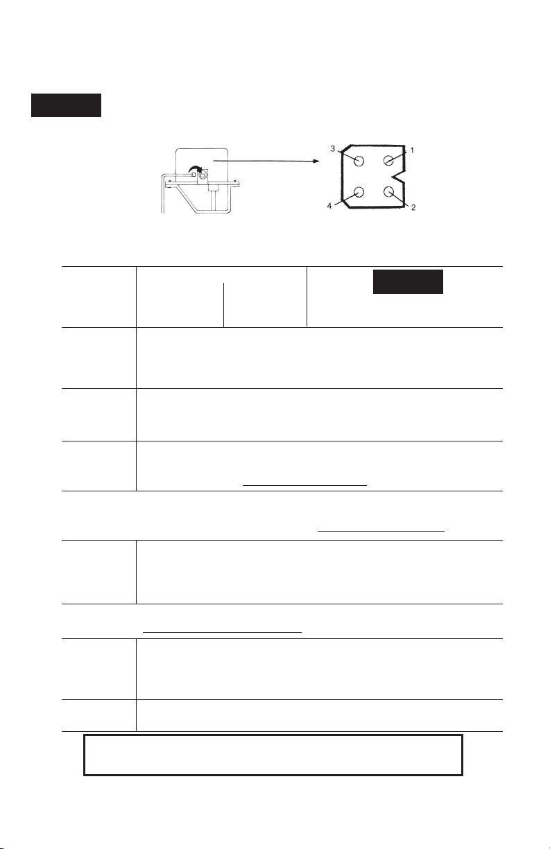
BOUCHON DU
VOLET EXTERIEUR
(VUE EXTRA MITE BROCHE)
ARRIVEE CABLAGE SUR VOLET
24 volts alt
COMMUN
SORTIE
SIGNAL
ENTREE SIGNAL
ARRIVEE 24 volts alt
1
2
3
4
RVGP-KS-BKF
TOUTES LES LECTURES SONT PRISES DE LA BOITE DE CABLAGE. NE PAS POUSSER
LES CONDUCTEURS DANS LA BOITE DE CABLAGE. CELA OUVRE LES FICHES ET FOSERA DES PROBLEMES DE CONTACT!
24 volts alt
COURANT
4 & 1
4 & 2
4 & 3
TOUT LE TEMPS
LORS DE DEMANDE DE CHALEUR
PENDANT COMBUSTION
OUVERT OU FERME
OUVERT OU EN COURS D´OUVERTURE
VOLET OUVERT
SEQUENCE DE L´OPERATION
NE PAS ANNULER L´ACTION DE TOUTE
COMMANDE DE SECURITE OU DE
FONCTIONNEMENT PRESENTE.
AVERTISSEMENT
PAS DE COURANT
4 & 1
LA POSITION 4 EST COMMUNE LA POSITION
1. MAUVAIS REGLAGE
2..TRANFORMATEUR DEFECTUEUX
3. FIL CASSE OU DESSERRE
1 EST ALIMENTEE 24 VOLTS ALT
4. FUSIBLE SAUTE OU DISJONCTEUR DISJONCTE
5. INTERRUPTEUR PRINCIPAL POSITION ARRET
6. CABLAGE NON BRANCHE DANS COFFRET DE L´APPAREIL
PAS DE COURANT
4 & 2
COURANT
4 & 1
1. LE THERMOSTAT N’A PAS DEMANDE DE CHALEUR
2. ANTICIPATEUR DE CHALEUR GRILLE
3. FIL CASSE OU DESSERRE
4. MAUVAIS REGLAGE, NIVEAU OU PRESSION
CONTROLE EAU INTERROMPU
5. INTERRUPTEUR MARCHE ARRET OBSTRUCTION
ORIFICE AERATION, OU RETOUR DE FLAMME
COURANT EN
4 & 1
4 & 2 SUR
VOLET OUVERT
ATTENTION POUR DIAGNOSTIC SEULEMENT. S´ASSURER QUE LE VOLET EST EN POSITION OUVERTE. UTILISER
L´INTERRUPTEUR DE COMMANDE POUR MAINTENIR LE VOLET EN POSITION OUVERTE. RELIER 2 & 3, SI L´APPAREIL
DEMARRE SEPARER 2 & 3 AINSI QUE LA PRISE A L´ARRIERE DU VOLET. SI L´APPAREIL NE DEMARRE PAS, REM-
PLACER LE CONTROLEUR DU VOLET. NE PAS REMPLACER L´ENSEMBLE DU TUBE.
SI UN CONTROLLER DE VOLET N´EST PAS DISPONIBLE, METTRE L´INTERRUPTEUR DE COMMANDE EN POSITION MAINTIEN OUVER-
TURE. CECI DEVRAIT MAINTENIR LE VOLET EN POSITION OUVERTE ET PERMETTRE A L´UTILISATEUR D´OBTENIR DE LA CHALEUR EN
AUTOMATIQUE. RENVOYER OU REMPLACER LE CONTROLEUR CELUI CI EST COUVERT PAR UNE GARANTIE DE 5 ANS A PARTIR DE LA
DATE D´INSTALLATION ORIGINALE. L´ENSEMBLE DU TUBE NE SERA PAS PRIS EN GARANTIE.
COURANT EN
4 & 1
4 & 2
4 & 3
VOLET OUVERT
PAS DE
COMBUSTION
1. VERIFIER QUE L´ARRIVEE DE GAZ EST OUVERTE
2. INTERRUPTEUR DE NIVEAU D’EAU,
INTERRUPTEUR DE SECURITE DE RETOUR D’AIR
CHAUD, INTERRUPTEUR DE RETOUR DE FLAMME
3. FIL CASSE OU DESSERRE
4. PIECE DEFECTUEUSE DANS L´APPAREIL EN AVAL
DU VOLET
LE VOLET TOURNE
CONTINUELLEMENT
REMPLACER LE CONTROLLEUR DU VOLET
NE PAS REMPLACER L´ENSEMBLE COMPLET
VOLET
GRIPPE
1. VERIFIER QUE DES VIS N´EMPECHENT PAS LE FONCTIONNEMENT
2. S´ASSURER QUE L´ENSEMBLE TUBE N´EST PAS DEFORME PAR L´ORIFICE D´AERATION OU PAR LA CHEMINEE
3. S´ASSURER QUE L´EXTREMITE RESSERREE DE L´ORIFICE D´AERATION N´EST PAS TROP ENFONCEE ET
EMPECHE LE MOUVEMENT DU VOLET
NOTA IMPORTANT LE VOLET DOIT ETRE EN POSITION OUVERTE AVANT LE COMMENCEMENT DE LA COMBUSTION
MODELE BRANCHABLE VOLET DE VENTILATION EFFIKAL RVGP DIAGNOSTIC DES PANNES
AVANT DE FAIRE L´ENTRETIEN DES COMMANDES, ETIQUETER TOUS LES FILS AVANT DE LES DEBRANCHER.
DES ERRBURS DE CABLAGE PEUVENT CAUSER UN FONCTIONNEMENT INEFFICACE ET DANGEREUX.
ATTENTION!
NE PAS OUVRIR LE VOLET MANUELLEMENT CAR LE MOTEUR SERA ENDOMMAGE. UTILISER L´INTERRUPTEUR DE
COMMANDE POUR BY-PASSER DISPOSITIF.
12
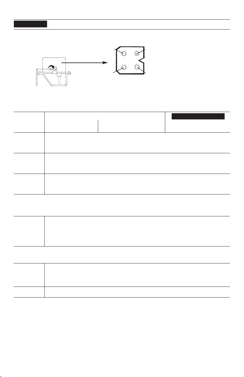
THIS IS NOT A WIRING DIAGRAM.
REFER TO PAGE 3 FOR WIRING DIAGRAM
PLUG-IN MODEL EFFIKAL RVGP SERIES TROUBLE SHOOTING GUIDE
VERIFY SAFE AND PROPER OPERATION
BEFORE LEAVING THE JOB SITE.
DO NOT CUT
PLUG OFF
OF DAMPER
CONTROLLER
OR WARRANTY
WILL BE VOID. PIN END VIEW
HARNESS RECEPTACLE
SIGNAL
OUT
External Damper Plug
All readings are taken from harness receptacle.
Do not push meter leads into harness receptacle. This opens the pins and will create connection problems!
RVGP-KS-BKF
CAUTION
WARNING
WHEN SERVICING CONTROLS ALL WIRES MUST BE LABELED PRIOR TO DISCONNECTION.
WIRING ERRORS CAN CAUSE IMPROPER AND DANGEROUS OPERATION.
Do not turn damper open manually or motor damage will result, use the service switch.
24VAC
COMMON
SIGNAL
IN
24VAC
HOT
IMPORTANT DAMPER MUST BE OPEN BEFORE COMBUSTION TAKES PLACE
If all steps have been tried and vent damper problems persist, call 248-370-9554
24 V.A.C.
POWER
4 & 1 All Times Open or Closed
4 & 2 Calling for Heat Open or Opening Do not negate the action of any
4 & 3 During Combustion Damper Open existing safety or operational controls
POSITION 4 IS COMMON POSITION 1 IS HOT 24VAC
NO POWER 1. Off on limit (120 VAC) 5. Disconnect switch off
4 & 1 2. Bad Transformer 6. Harness not plugged into appliance
3. Loose or broken connections Receptacle
4. Blown fuse or circuit breaker
NO POWER 1. Thermostat not calling for heat 4. Off On Operating limit, pressure
4 & 2 2. Burned out heat anticipator control or low water cut off.
POWER ON 3. Loose or broken connections 5. Off On blocked vent switch or flame
4 & 1 Roll out
POWER ON 1. Check to make sure gas is on 3. Loose or broken connections
4 & 1 2. Off on low water cut off, blocked vent 4. Defective component in appliance after
4 & 2 switch or flame roll out switch the vent damper
4 & 3 WHEN JUMPER IS IN PLACE — FOR TROUBLE SHOOTING ONLY
1. Make sure no screws are obstructing damper blade 4. For additional information see page 5.
2. Make sure damper pipe assembly is not egg shaped
caused by the vent pipe or chimney opening
3. Make sure the crimped end of the vent pipe is not
shoved in so far to obstruct the damper blade
POWER ON
4 & 1
4 & 2
DAMPER OPEN
DAMPER OPEN
NO COMBUSTION
If a damper controller is not available place the service switch in the hold open position. This should keep the damper in
the open position and allow the customer to have automatic heat. Return or replace the controller at your convenience. The
controller carries a 5 year warranty from the original date of installation. Pipe assembly will not be warranted.
WARNING for trouble shooting only. Make sure damper is in the open position. Use the service
switch to keep the damper in the open position. Place a jumper between 2 & 3 if the appliance
fires remove jumper & plug receptacle back into damper controller plug. If appliance does not fire
replace damper controller. Do not replace the pipe assembly.
NORMAL SEQUENCE OF OPERATION
DAMPER ROTATES
CONTINUOUSLY
DAMPER
STICKS
Change the damper controller
Do not change the entire damper assembly
DO NOT REPLACE THE ENTIRE DAMPER ASSEMBLY –
REPLACE ONLY THE MOTORIZED CONTROLLER.
Table of contents


