Installation Instructions 85002 │Gas Valve 120Vrac VK4115
| 3
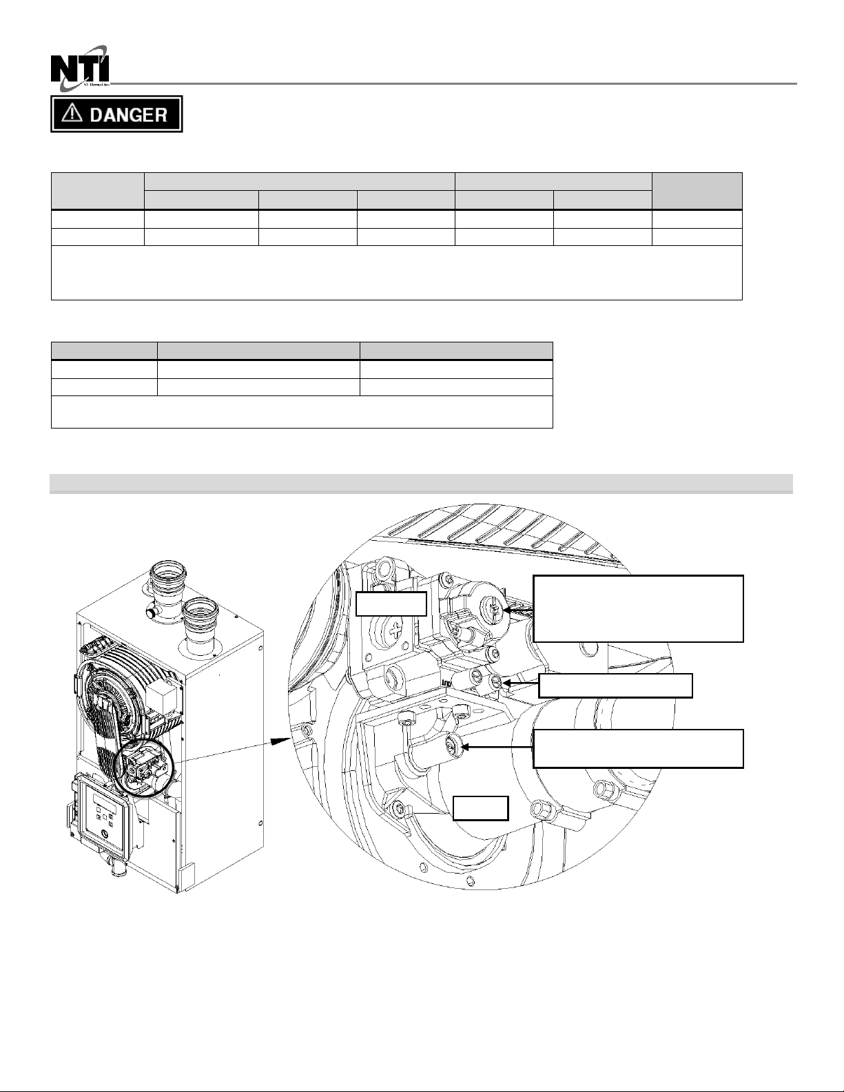
Throttle Screw Adjustment
The gas valve Throttle Screw (see Figure 3) is used to calibrate the CO2concentration with the burner operating at or
near the maximum modulation rate (see Table 2). Turning the Throttle Screw in (clockwise) decreases the CO2
concentration. Turning the Throttle Screw out (counterclockwise) increases the CO2 concentration. Typical adjustment
required is 0 –1/2of a turn in or out from the factory setting.
NOTE: Calibration of the Throttle Screw should only be performed with the burner operating at or near the
maximum modulation rate (see Table 2).
Adjustments to the Throttle Screw may only be made by a qualified gas technician using a
calibrated combustion analyzer capable of measuring CO2and CO. Adjustments may only be
performed if the gas line pressure is maintained above minimum levels throughout the duration
of the test (see Table 1). Failure to follow these instructions may result in serious injury or death.
Offset Screw Adjustment
The gas valve Offset Screw (see Figure 3) is used to calibrate the CO2offset at minimum modulation vs. maximum
modulation. Turning the Offset Screw in (clockwise) increases the CO2 concentration at minimum modulation rate.
Turning the Offset Screw out (counterclockwise) decreases the CO2 concentration at minimum modulation rate. Typical
adjustment required is 0 - 1/8th of a turn in or out from the factory setting.
NOTE: Calibration of the Offset Screw must only be performed with the burner operating at the minimum
modulation rate (see Table 2).
Adjustments to the Offset Screw may only be made by a qualified gas technician using a
calibrated combustion analyzer capable of measuring CO2and CO, and only with the burner at
the minimum modulation rate (see Table 2). Attempting to set the Offset Screw while the burner
is operating at a modulation rate other than the minimum will result in incorrect combustion and
may lead to burner damage or excessive CO.
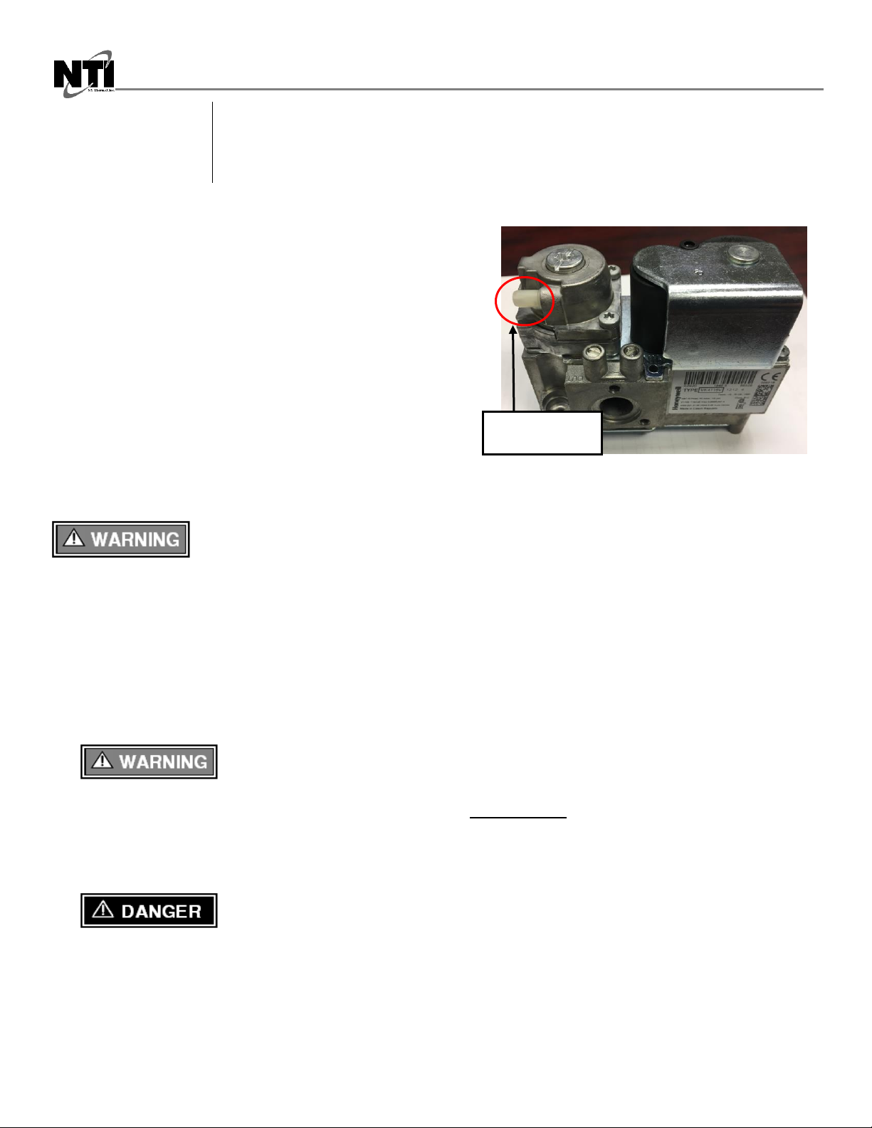
Gas Line Pressure Test
The boiler gas valve is equipped with a line pressure test port; see Figure 3. Use the following procedure to measure the
gas line pressure to the boiler to ensure it falls within the range given in Table 1:
1. Turn the supply of gas to the boiler off.
2. Open the bleed screw of the line pressure test port approximately 1-1/2 turns. This port is directly connected to the
gas line feeding the boiler. See Figure 3.
3. Force 1/4ID tubing over the housing of the line pressure test port; install the other end of the tubing to an
appropriate line pressure test gauge or manometer. Ensure both ends of the tubing make a tight connection.
4. Open the supply of gas to the boiler and check for gas leaks.
5. Observe the line pressure under static conditions and compare it to Table 1. The pressure will be greatest under
static conditions.
6. With all other gas appliances in the application running, operate the burner to the maximum firing rate (See Table 2)
and compare the observed line pressure with Table 1. The pressure will be lowest during the maximum flow of gas.
7. Adjust the gas line pressure to ensure the parameters in Table 1 are attained under all conditions. If possible adjust
the line pressure to the "Nominal/Desired" value listed in Table 1, while the unit is operating at the maximum
modulation rate, see Table 2.
8. Continue observing the gas line pressure until the completion of the combustion analyses, in case adjustments need
to be made.
9. Complete pressure testing, and then return the bleed screw of the Line Pressure Test Port to the closed position.
The line pressure is a function of the gas supply and is affected solely by field provided
parameters such as line size and regulator settings. Under no circumstances can the boiler gas
valve influence or be used to adjust the gas line pressure.