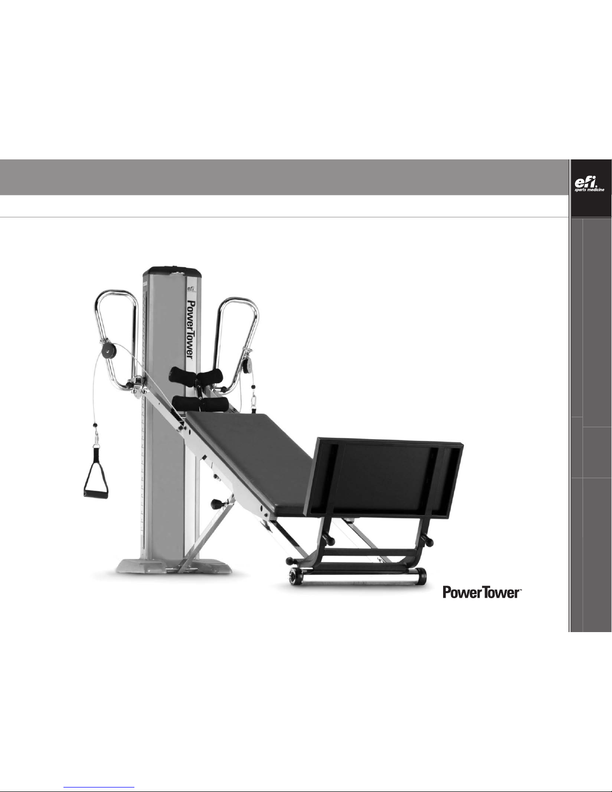
EFI POWER TOWER User manual
TOTAL GYM®POWER TOWERTM OWNER’S GUIDE
OWNER’S GUIDE TOTAL GYM®POWER TOWERTM
800 541 4900 EFISPORTSMEDICINE.COM

©2005, efi Corporation.
CONGRATULATIONS
Thank you for purchasing Total Gym®PowerTower™.We welcome you as a
valued customer and trust your PowerTower will provide you with unsurpassed
convenience and versatility year after year.
Functional exercise equipment from efi Sports Medicine has set the standard for
physical rehabilitation, athletic training and sports performance training for more
than three decades.
Now, PowerTower adds the dynamic dimension of electrical power.
It allows:
•Unrestricted movement through all three planes of motion
•Proprioceptive training in everymovement
•Recruitment of the core automatically
•Unloaded, early closed-chain exercise in a functional environment
•Calibrated, incremental increases and decreases in load
PowerTower enables you to fine-tune clients’ exercise regimens. Resistance is
adjustable during an exercise in progress with the press of a switch. The client
remains on the glideboardas you raise or lower the level of resistance.
As a result, your clients experience fewer transitions and more cohesive exercise
sessions. Plus, adjusting the resistance level is effortless.
Your PowerTower arrives with very little required in the way of assembly. Simply
follow this Guide and in minutes your PowerTower will be operational.
In this Guide you will find tips about PowerTower and its
component parts, operation, maintenance and care. Additionally,
you will find safety tips and precautions to help ensure your
safety and the safety of your patients and clients. Your Guide also
includes warranty information. Please save this Owner's Guide and
refer to it in the future.
If you have any questions about PowerTower or if you need service,
please contact us. Our goal is to provide you with the premier
training tool for functional exercise, and we stand ready to assist
you every step of the way.
Sincerely,
Tom Campanaro,
President/CEO
efi Sports Medicine
7755 Arjons Drive
San Diego, CA 92126
U.S.A. area code (858) 586-6080
800 541 4900 toll-free inside U.S.A.
CAUTION: As with any exercise program, participants should consult a physician before starting a workout on PowerTower. Changes or modifications to this PowerTower may void the
warranty and may violate U.S. Federal Communications Commission (FCC) Rules. Weight Capacity: PowerTower is rated at a maximum user weight capacity of 350 lbs [160 kg].
Additional weights with a weight bar can be applied to the glideboard. Do not exceed 650 lbs [295 kg] of weight-bearing on the PowerTower.

TOTAL GYM®POWER TOWERTMOWNER’S GUIDE
OWNER’S GUIDE TOTAL GYM®POWER TOWERTM
800 541 4900 EFISPORTSMEDICINE.COM
1
TOTAL GYM®POWER TOWERTMOWNER’S GUIDE
TABLE OF CONTENTS
Parts Identifier..............................................................................................................................................................................................2
Box and Hardware Packet Contents..............................................................................................................................................................3
Warnings ..............................................................................................................................................................................................................4
Fuse Replacement ........................................................................................................................................................................................4
Grounding Instructions ................................................................................................................................................................................5
FCC Rules..............................................................................................................................................................................................................6
Specifications ..............................................................................................................................................................................................6
Parts Assembly..........................................................................................................................................................................................7-8
Installing LAT Bars ..................................................................................................................................................................................9-13
Adjusting LAT Bars......................................................................................................................................................................................14
Folding Platform........................................................................................................................................................................................15
Telescoping Squat Stand ............................................................................................................................................................................16
Pulley Locator Brackets ..............................................................................................................................................................................16
Rail Lock & Screw (optional) ......................................................................................................................................................................16
Folding Foot Holder ....................................................................................................................................................................................17
Adjusting the Rail Handle ..........................................................................................................................................................................18
Folding and Storage ..............................................................................................................................................................................19-22
Getting Started......................................................................................................................................................................................23-24
Safety Precautions......................................................................................................................................................................................25
Troubleshooting ..........................................................................................................................................................................................26
Maintenance and Care................................................................................................................................................................................27
Reading Resistance Chart ..........................................................................................................................................................................27
Resistance Chart ........................................................................................................................................................................................28
Warranty Information ..................................................................................................................................................................................29
2
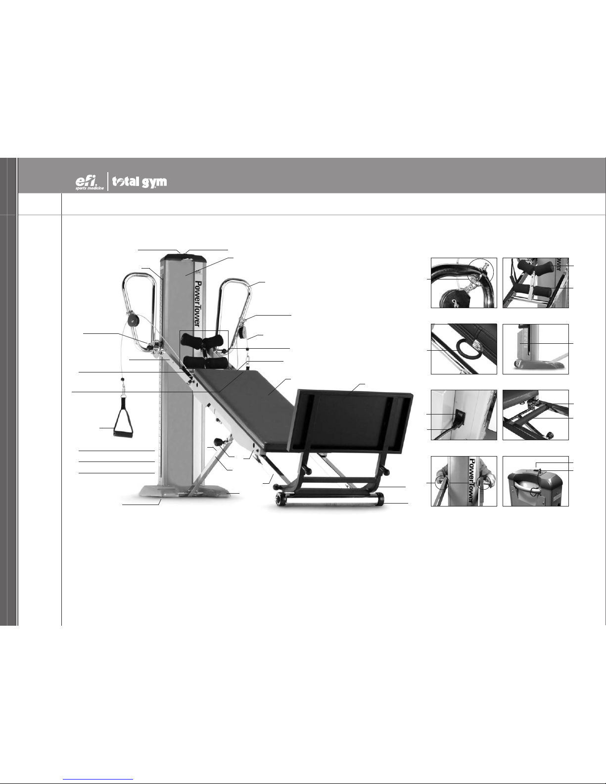
PARTS IDENTIFIER - POWER TOWERTM
INSET 2.
A. Tower
B. Lateral Adjustable Training
(LAT) bars
C. Pulley Locator Brackets
D. Dynamic Arm Pulley System
E. Folding Foot Holder
E1. Upper Foot Pad Assembly
E2. Lower Foot Pad Assembly
F. Glideboard “D” Ring
G. Glideboard
H. Telescoping Squat Stand
I. Folding Platform
J. Lower Rail Base
K. Lower Rails
L. Glideboard Wheel Housing
M. Support Strut Knob
N. Support Strut
O. Emergency Stop Touchpad
P. Tower Base
Q. TransportWheels
R. Electric DC Motor
S. Power Cord
T. On/Off Switch
U. Handles
V. Rail Lock
W. Center Rail Crossbar
X. Upper Rails
Y. Tower Crossbar
Z. Tower Slot
ZX. Safety Key
ZY. Up/Down Switch
A
B
C(see INSET 1)
D
E(see INSET 2)
E1
E2
F(see INSET 3)
^
INSET 3.
GH
I
J
K
L
M
N
O
^
P
Q
^
R(on back of Tower; see INSET 4)
^
S(on back of Tower; see INSET 5)
^
T(on back of Tower; see INSET 5)
^
^
ZX (see INSET 8)
^
Z
W(on back of Tower; see INSET 6)
^
V(on back of Rail; see INSET 6)
^
U
X
INSET 1.
C
F
INSET 4. (SIDE VIEW)
R
T
INSET 5. (BACK SIDE VIEW)
S
INSET 6.
W
Y
INSET 7. (SIDE VIEW) INSET 8. (BACK TOP VIEW)
ZY
When parts are referenced
throughout this guide,
corresponding letters from
this PARTS IDENTIFIER page
are also listed. For example,
when “Tower” appears within
this guide, (A) will appear
behind “Tower” as a cue to refer
back to this page if needed.
V
Y(see INSET 7)
^
ZX
^
ZY (see INSET 8)

TOTAL GYM®POWER TOWERTMOWNER’S GUIDE
OWNER’S GUIDE TOTAL GYM®POWER TOWERTM
800 541 4900 EFISPORTSMEDICINE.COM
3
PARTS ASSEMBLY - POWER TOWERTM
Your PowerTower
TM
arrives with some assembly required. Enclosed in your PowerTower
TM
boxes you will find:
HARDWARE PACKET CONTENTS
AA. Tower, Rail &
Glideboard Assembly
BOX CONTENTS BB. LAT Bars & Arm Pulley
Cable Assembly
CC. Folding Platform DD. Telescoping Squat Stand
EE. Empty Spacer Box FF. One Hardware Packet Box
NN. Handles (2)MM. PowerTower Owner’s Guide (1)LL. Quick Links (2)
JJ. Socket Head Screws (2)II. Chrome Washers (2)HH. Bronze Washers (4)GG. Wrenches (2)
Wrench handle
is a hex key.
OO. Safety Key (1)
KK. Rail Lock Screw (1)

4
NOTE: Letters in (parentheses) refer to the PARTS IDENTIFIER on page 2 and/or the PARTS ASSEMBLY on page 3. Use as needed for clarification.
IMPORTANT INFORMATION ABOUT YOUR
POWER TOWERTM
Your PowerTowerTM is an electrically powered
device. When using an electrical appliance,
basic precautions should always be followed,
including the following:
READ ALL INSTRUCTIONS BEFORE USING
THE POWER TOWER
DANGER –to reduce the risk of electric shock,
always unplug the PowerTower from the
electrical outlet immediately after using and
before cleaning.
WARNING – To reduce the risk of burns, fire,
electric shock, or injuryto persons:
1. Inspect the PowerTower before each use
to ensureproper operation. Do not use
this equipment unless all moving parts
are working properly.
2. The PowerTower should never be left
unattended when plugged in. Unplug
from outlet when not in use, and before
putting on or taking off parts.
3. Keep the area near the base of the
Tower (A) clear to allow air flow into the
motor. Keep towels, blankets or loose
clothing off and clear of PowerTower and
its surrounding area. Keep all openings
free of lint, hair, and the like.
4. Close supervision is necessary when this
equipment is used by, on, or near
children, invalids, disabled or injured
persons.
5. Care should be taken at all times when
getting on and off the PowerTower or any
exercise equipment. Falling on or off the
product could result in injury, or
possibly death.
6. Use the PowerTower only for its intended
use. Do not use attachments not
recommended by the manufacturer.
7. Never operate the PowerTower if it has a
damaged Power Cord(S) or plug, if it is
not working properly, emits an odor or
unusual noise, if it has been dropped or
damaged, or dropped into water. Contact
the manufacturer for examination and
repair.
8. Do not pull the PowerTower by the Power
Cord(S) or use the Power Cord(S) as a
handle.
9. Keep the Power Cord (S) away from heated
surfaces.
10. Place the PowerTower on a flat level
surface. Allow ample clearance for the
Rails (K, X) to lower to their fully extended
position. Do not store anything under
the PowerTower.
11. Never drop or insert any object, including
fingers, into any PowerTower opening.
12. Do not use the PowerTower outdoors.
13. Do not operate where aerosol (spray)
products are being used or where oxygen
is being administered.
14. To disconnect, turn all controls to the OFF
position, then remove plug from outlet.
15. Keep fingers, loose clothing, and hair
away from moving parts.
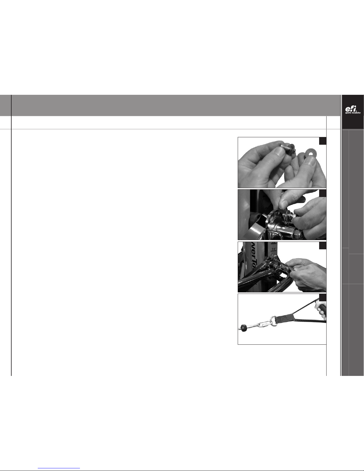
FUSE REPLACEMENT
To replace 5A Fuse in Tower (A) back:
- Unplug the Power Cord (S) from the
power outlet.
-Locate the fuse assembly near the power
outlet on the Tower (A).
- Use a flathead screwdriver to pull out
the fuse assembly.
- There are (2) 5A fuses in the fuse assembly.
One is a spare.
- The other is in use (Fig. 1).
- Remove the old fuse from the clamp.
- Push the old fuse far enough into the hole of
the fuse assembly to release the spare fuse
(Fig. 2).
- Place the sparefuse into clamp (Fig. 3).
-Dispose of the old fuse. Replace the
fuse assembly.
Figure 1
Figure 2
Figure 3

TOTAL GYM®POWER TOWERTMOWNER’S GUIDE
OWNER’S GUIDE TOTAL GYM®POWER TOWERTM
800 541 4900 EFISPORTSMEDICINE.COM
5
NOTE: Letters in (parentheses) refer to the PARTS IDENTIFIER on page 2 and/or the PARTS ASSEMBLY on page 3. Use as needed for clarification.
IMPORTANT NOTICE ABOUT
PROPER GROUNDING
WARNING: Connect the
PowerTower
TM
to a properly
grounded outlet only. Improper
connection of the equipment
grounding connector can result
in the risk of electric shock. Do
not modify the plug that is
provided with the PowerTower. If
it will not fit in the outlet, have
aproper outlet installed by a
qualified electrician.
See grounding instructions.
Figure 1
FOLLOW THESE GROUNDING INSTRUCTIONS
The PowerTower must be grounded. If it should
malfunction or break down, grounding provides a
path of least resistance for electric current to reduce
the risk of electric shock.
The PowerTower is equipped with a Power Cord (S)
having an equipment-grounding conductor and a
grounding plug. The plug must be plugged into an
appropriate outlet that is properly installed and
grounded in accordance with all local codes
and ordinances.
DANGER - Improper connection of the equipment-
grounding conductor can result in a risk of electric
shock. Check with a qualified electrician or
serviceman if you arein doubt as to whether the
product is properly grounded. Do not modify the plug
provided with the
product – if it will not fit the outlet,
have a proper outlet installed by a qualified electrician.
Depending on your country of residence, you can
purchase a 120 VAC or 230 VAC PowerTower.
Some adapters may be permitted, similar to the type
explained below:
APowerTower that is for use on a nominal 120-volt
circuit has a grounding plug that looks like the plug
illustrated in Figure1. Atemporaryadapter that looks
like the adapter illustrated in Figure2may be used
to connect this plug to a 2-pole receptacle as shown
in Figure 2 if a properly grounded outlet is not
available. The temporaryadapter should be used
only until a properly grounded outlet (Figure 1) can
be installed by a qualified electrician. The green
colored rigid ear, lug, or the like extending from the
adapter must be connected to a permanent ground
such as a properly grounded outlet box cover.
Whenever the adapter is used, it must be held in
place by a metal screw.
Figure 2
6
NOTE: Letters in (parentheses) refer to the PARTS IDENTIFIER on page 2 and/or the PARTS ASSEMBLY on page 3. Use as needed for clarification.
FCC RULES
Warning: Changes or modifications to this unit not expressly approved by
the party responsible for compliance could void the user’s authority to
operate the equipment.
NOTE: This equipment has been tested and found to comply with the limits
for a Class B digital device, pursuant to Part 15 of the FCC Rules. These
limits are designed to provide reasonable protection against harmful
interference in a residential installation. This equipment generates, uses
and can radiate radio frequency energy and, if not installed and used in
accordance with the instructions, may cause harmful interference to
radio communications.
However, there is no guarantee that interference will not occur in a
particular installation. If this equipment does cause harmful interference
to radio or television reception, which can be determined by turning the
equipment off and on, the user is encouraged to try to correct the
interference by one or more of the following measures:
- Reorient or relocate the receiving antenna.
-Increase the separation between the equipment and receiver.
-Connect the equipment into an outlet on a circuit different from
that to which the receiver is needed.
Consult the dealer or an experienced radio/TV technician for help.
SPECIFICATIONS
Power:
115 Volts and 5 Amps or
230 Volts and 3 Amps
50 or 60 cycles depending on the country where it is sold.
Incline Speed:
Approximately 30 seconds to ascend/
20 seconds to descend. (Varies under load)
Dimensions:
Standing: 110” x 36” x 76” [L/W/H]
(2.5 m x .9 m x 1.9 m)
Folded: 24” x 36” x 63” [L/W/H]
(.6 m x .9 m 1.5 m)
Resistance:
•4° to 34° increments are marked.
•11 levels of calibration at 3° increments
appear on the Resistance Chart(see page 28).
•3% to 72% of body weight
User Height Limit:
6’5” (2.0 m)
Weight Capacity:
PowerTowerTM is rated at a maximum user weight capacity of
350 lbs. [160 kg]. Additional weights can be applied to the
glideboardon a weight bar,up to 650 lb [295 kg] maximum total.
ETL #3100548FCC ID: UHJPOWERTOWER

TOTAL GYM®POWER TOWERTMOWNER’S GUIDE
OWNER’S GUIDE TOTAL GYM®POWER TOWERTM
800 541 4900 EFISPORTSMEDICINE.COM
7
NOTE: Letters in (parentheses) refer to the PARTS IDENTIFIER on page 2 and/or the PARTS ASSEMBLY on page 3. Use as needed for clarification.
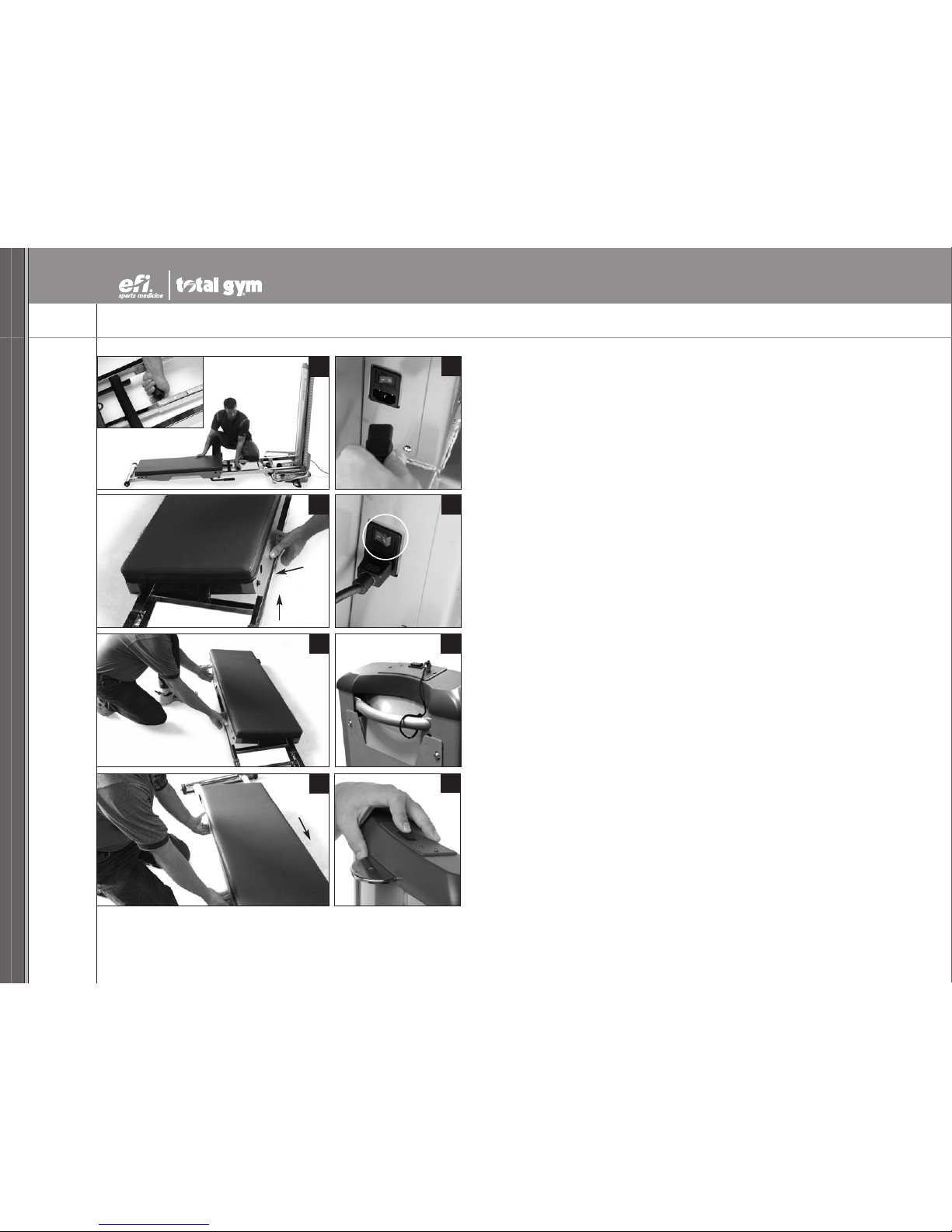
PARTS ASSEMBLY
PUTTING YOUR POWER TOWER
TM
INTO OPERATION IS EASY.
1. To begin assembly, remove your
PowerTowerTM
from the box. Stand the PowerTower upright.
Find Hardware Packet (see page 3 for Hardware Packet Contents).
2. Pull and twist the retractable Support Strut Knob (M) to loosen it.
POWER TOWER SET-UP
3. While unfolding the PowerTower, as an extra precaution, hold the side of the Tower (A)
with one hand to steady the Tower (A).
4. With the other hand, push the Lower Rails (K) off and away from the Tower Base (P)
by grasping the padded Center Rail Crossbar (W)and allow the Rails (K, X) to unfold
slowly away from the Tower (A) until the Rails (K, X) are fully extended.
CAUTION: Do not touch the hinge.
1
2
3
4
8
NOTE: Letters in (parentheses) refer to the PARTS IDENTIFIER on page 2 and/or the PARTS ASSEMBLY on page 3. Use as needed for clarification.
PARTS ASSEMBLY (CONTINUED)
5. Engage and tighten the SupportStrut Knob (M). You need to lean
the tower backward slightly to engage the pin.
IMPORTANT SAFETY NOTICE: The Support Strut Knob (M) must be
engaged and tightened during PowerTower
TM
use.
6. Remove the packing foam from the four wheels. To reposition the
Glideboard (G) for use, kneel beside the Glideboard (G). Lift and
pull one side of the metal Glideboard Wheel Housings (L) away
from the Rails (K, X).
7. Lift the opposite side of the Glideboard(G) until the wheels lift
completely offthe Rails (K, X).
8. Move the Glideboard(G) about 6 inches up the Rails (K, X)
toward the Tower (A), until the metal stop on the underside of
the Glideboard (G) rests above the rubber bumper. Lower the
Glideboard(G) and pull the GlideboardWheel Housings (L) out
as you lower the Glideboard (G) back into place.
9. Connect the Power Cord (S) to the back of the PowerTower.
Then connect the PowerTower to an appropriate receptacle.
10. Turn on the PowerTower with the On/Off Switch (T) at the bottom
back of the Tower (A).
11. Remove the Safety Key (ZX) from the Hardware Packet. Use the
loop in the Safety Key (ZX) lanyardto tie it to the Tower’s (A)
back handle. Insertthe Safety Key (ZX) into the hole on top of
the Tower (A). Your PowerTower will not operate if the Safety Key
(ZX) is not in place.
12. Raise the Rails (K, X) to the desired level by using the Up/Down
Switch (ZY) on top of the Tower (A).
3
5
6
7
8
9
10
11
Lift
Pull
12

TOTAL GYM®POWER TOWERTMOWNER’S GUIDE
OWNER’S GUIDE TOTAL GYM®POWER TOWERTM
800 541 4900 EFISPORTSMEDICINE.COM
9
NOTE: Letters in (parentheses) refer to the PARTS IDENTIFIER on page 2 and/or the PARTS ASSEMBLY on page 3. Use as needed for clarification.
13
INSTALLING LAT BARS
13. Raise the Rails (K, X) to Tower (A) to 20 degrees for ease of assembly, as shown.
14. Ensure that the Support Strut Knob (M) is engaged and tight.
REMOVE THE SHIPPING SLEEVES - PHASE 1
15. Your PowerTower
TM
arrives with shipping sleeves on the ends of the Tower Crossbar (Y).
The shipping sleeves serve one purpose: to protect the Tower Crossbar (Y) during shipping.
16. NOTE: For easiest assembly, keep the Tower Crossbar (Y) centered throughout the assembly
process, with each end extending about equal distance from the Tower (A).
HARDWARE PACKET TOOLS NEEDED: To remove the first shipping sleeve, face the Tower (A)
back and take one of the supplied Wrenches (GG) in each hand. The Wrenches (GG)are
located in the Hardware Packet (contents shown on page 3).
14
15
16

10
NOTE: Letters in (parentheses) refer to the PARTS IDENTIFIER on page 2 and/or the PARTS ASSEMBLY on page 3. Use as needed for clarification.
INSTALLING LAT BARS (CONTINUED)
17. Apply one Wrench (GG) to the nyloc nut on one side of the Tower Crossbar (Y). Use the
other Wrench (GG) to loosen the nyloc nut on the other side of the Tower Crossbar (Y) by
turning counterclockwise. Set the shipping sleeve aside.
18. Remove the nyloc nut, Chrome Washer (II) and the Bronze Washer (HH). Set them aside.
19. Lift the Upper Rail (X) with one hand. Remove the first shipping sleeve from the
Tower Crossbar (Y) with the other hand.
20. To remove the remaining shipping sleeve, immobilize the exposed end of the
Tower Crossbar (Y) by applying one of the Wrenches (GG) to the notch.
17
18
19
20

TOTAL GYM®POWER TOWERTMOWNER’S GUIDE
OWNER’S GUIDE TOTAL GYM®POWER TOWERTM
800 541 4900 EFISPORTSMEDICINE.COM
11
NOTE: Letters in (parentheses) refer to the PARTS IDENTIFIER on page 2 and/or the PARTS ASSEMBLY on page 3. Use as needed for clarification.
INSTALLING LAT BARS (CONTINUED)
21. Use the other Wrench (GG) to loosen the remaining nyloc nut by turning it counterclockwise.
22. Hold the Upper Rail (X) with one hand. Remove the shipping sleeve from the Tower
Crossbar (Y) with the other hand. Set the shipping sleeve aside.
Now that the shipping sleeves have been removed, you are ready to attach the first
LAT Bar (B). You may discard the shipping sleeves or retain them in the event you need
to ship your PowerTower
TM
in the future.
POSITIONING THE LAT BARS - PHASE 2
23. Toposition the first LATBar (B) for mounting, make surethe long, vertical side of the
LATBar (B) aligns closest to the Tower (A). (The slotted holes face the back of the
PowerTower, the black knob on the LAT Bar (B) faces the Glideboard (G).)
24. Slide a Bronze Washer (HH) onto the LAT Bar (B) cylinder. Stand beside the Tower (A) and
align the LATBar (B) cylinder with the Tower Crossbar (Y).
REMINDER: Keep the Tower Crossbar (Y) centered during assembly.
25. Slide the LAT Bar (B) cylinder onto the Tower Crossbar (Y) until it is securely seated on the
Upper Rail (X).
HINT: You will need to lift the Upper Rail (X) to slide the LAT Bar (B) cylinder inside the hole
in the Upper Rail (X).
21
23
24
25
22

12
NOTE: Letters in (parentheses) refer to the PARTS IDENTIFIER on page 2 and/or the PARTS ASSEMBLY on page 3. Use as needed for clarification.
INSTALLING LAT BARS: POSITIONING THE LAT BARS - PHASE 2 (CONTINUED)
26. Rotate the LATBar (B) upside-down until the other LAT Bar (B) is installed, and both nyloc nuts
on the Tower Crossbar (Y) have been tightened.
27. Return the Chrome Washer (II) to the end of the Tower Crossbar (Y) that extends beyond the
LAT Bar (B) cylinder.
Attach and finger tighten the nyloc nut onto the Tower Crossbar (Y) with the other hand.
28. Press against the nyloc nut to push the Tower Crossbar (Y) until it lies flush against the
LAT Bar (B) cylinder. This will help seat the LAT Bar (B) against the Upper Rail (X).
Repeat Phase 2 for the other LAT Bar (B). Tighten both LAT Bars (B) with the Wrenches (GG)
until the nyloc nuts get hard to turn (no threads should be showing).
ATTACHING THE LAT BAR BRACKET - PHASE 3
29. Remove the remaining contents (shown on page 3)from your Hardware Packet. Lower the
LAT Bar (B) to the Pull-up position.
26
27
28
29
TOTAL GYM®POWER TOWERTMOWNER’S GUIDE
OWNER’S GUIDE TOTAL GYM®POWER TOWERTM
800 541 4900 EFISPORTSMEDICINE.COM
13
NOTE: Letters in (parentheses) refer to the PARTS IDENTIFIER on page 2 and/or the PARTS ASSEMBLY on page 3. Use as needed for clarification.
INSTALLING LAT BARS: ATTACHING THE LAT BAR BRACKET - PHASE 3 (CONTINUED)
30. Place a Chrome Washer (II) followed by a Bronze Washer (HH) on a Socket Head Screw (JJ).
31. Feed the Socket Head Screw (JJ) partially through the elongated slot.
Place another Bronze Washer (HH) on the Socket Head Screw (JJ) on the other side of
the bracket.
Thread the Socket Head Screw (JJ) into the hole in the rail. Align the Socket Head Screw (JJ)
with the hole in the Upper Rail (X) inside the LAT Bar (B) bracket. Finger tighten the Socket
Head Screw (JJ)
32. Tighten the Socket Head Screw (JJ) with the hex end handle of the Wrench (GG).
Repeat Phase 3 (Attaching the Lat Bar Bracket) on the opposite side.
33. Attach the Handles (U) to the ends of the Dynamic Arm Pulley System (D) using the
Quick Links (LL).
With these steps completed, your LAT Bars (B) are assembled.
30
31
32
33
14
NOTE: Letters in (parentheses) refer to the PARTS IDENTIFIER on page 2 and/or the PARTS ASSEMBLY on page 3. Use as needed for clarification.
ADJUSTING THE LAT BARS
34. To adjust the LAT Bars (B), pull the retractable knob on the LAT Bar to disengage the Lat Bar
from the Upper Rail (X) and rotate LAT Bars to the desired position. Ensure that the pin on the
retractable knob is properly engaged.
LAT BAR ADJUSTS TO THREE POSITIONS
35. NORMAL USE: parallel (upright) to the Tower (A), perpendicular to Rails (K,X)
36. PULL-UP POSITION: angled upwards from the Rails (K,X)
37. FOLD UP POSITION: parallel to the Rails (K,X)
Knob
34
35
36
37
TOTAL GYM®POWER TOWERTMOWNER’S GUIDE
OWNER’S GUIDE TOTAL GYM®POWER TOWERTM
800 541 4900 EFISPORTSMEDICINE.COM
15
NOTE: Letters in (parentheses) refer to the PARTS IDENTIFIER on page 2 and/or the PARTS ASSEMBLY on page 3. Use as needed for clarification.
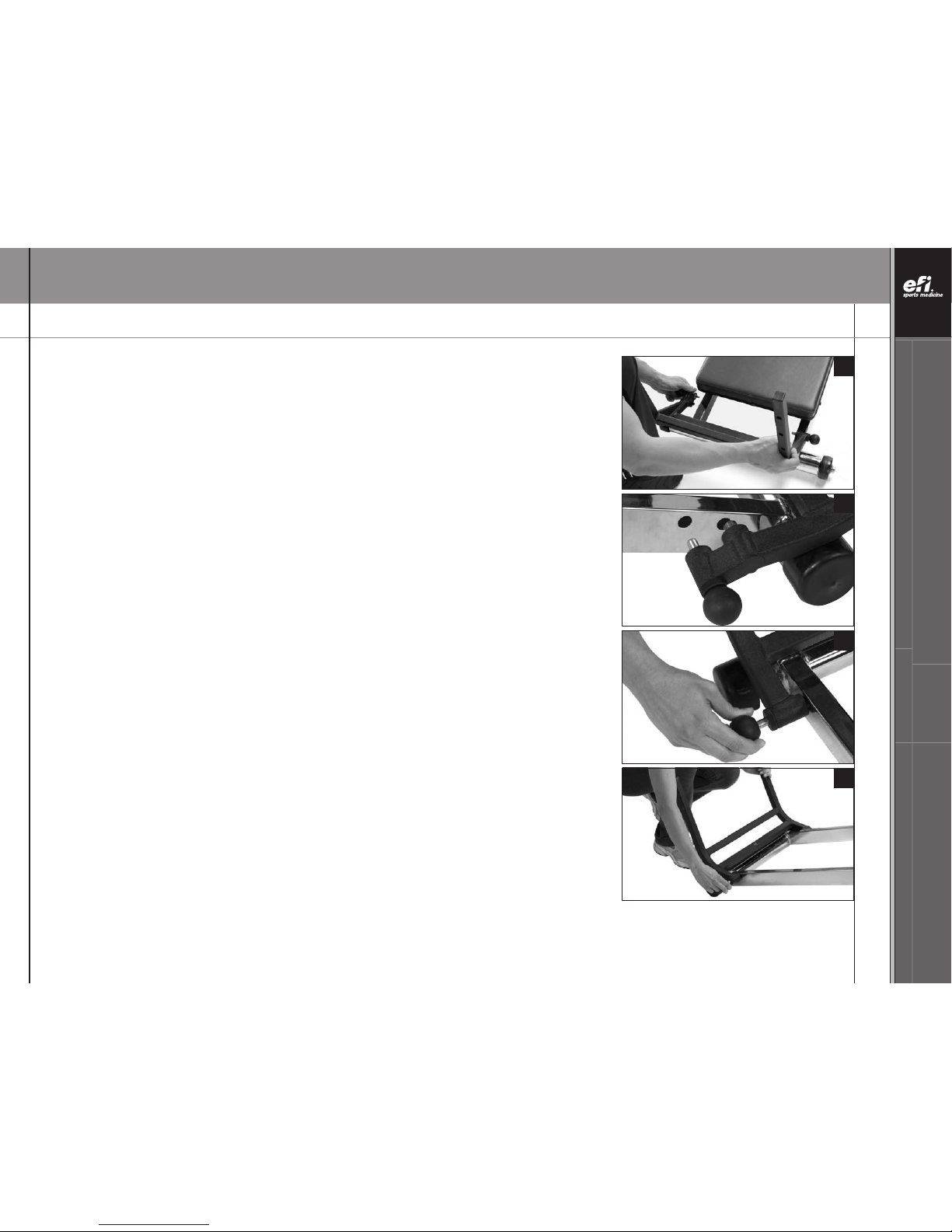
FOLDING PLATFORM
38. Align the bottom of the Folding Platform (H) with the Lower Rails (K) just above the
Lower Rail Base (J).
39. Using the two holes just above the Lower Rail Base (J), slide the fixed pin into the hole
in the outside left Lower Rail as you face the Tower (A).
40. Pull the retractable pin on the right side and move the pin over the hole. Release the pin.
41. Move the Folding Platform(H) until all the pins engage completely.
38
39
40
41
16
NOTE: Letters in (parentheses) refer to the PARTS IDENTIFIER on page 2 and/or the PARTS ASSEMBLY on page 3. Use as needed for clarification.
TELESCOPING SQUAT STAND
42. Align the Telescoping Squat Stand (H) over the Folding Platform (I) struts until the
Telescoping Squat Stand (H) pins contact the top of the Folding Platform (I) struts.
43. Pull the retractable pins and adjust the Telescoping Squat Stand (H) to the desired height,
then release the pins and raise or lower the Telescoping Squat Stand (H) until both pins
engage in one of the three adjustment holes in the Folding Platform (I) struts.
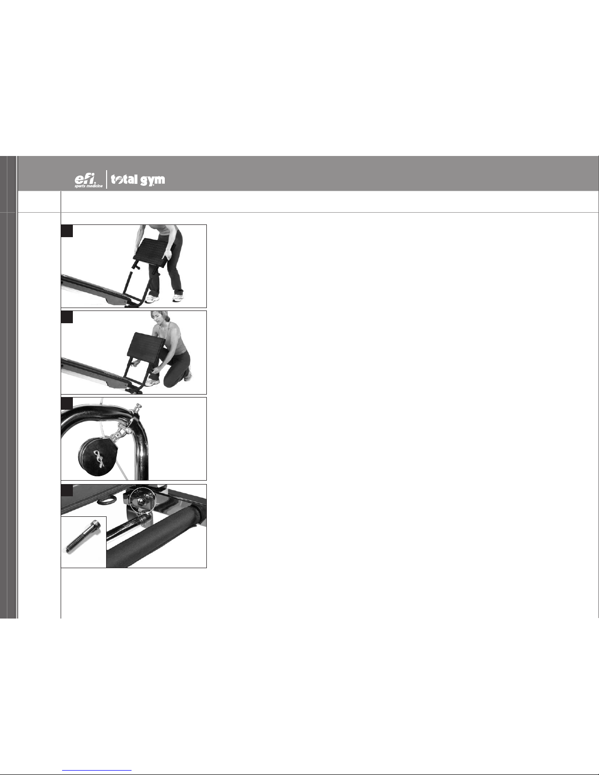
PULLEY LOCATOR BRACKETS
44. The Pulley Locator Brackets (C) are designed to adjust easily. Pull back on the pin, move the
Pulley Locator Bracket (C) to the desired position on the LAT Bars (B) and allow the pin to
engage the slotted hole. You should rotate the pulley toward the center of the LAT Bar as
shown when moving the Pulley Locator Bracket (C) around the bends.
RAIL LOCK & SCREW (OPTIONAL)
45. If you intend to use your PowerTower
TM
to do plyometrics at high inclines, and you do not intend
to fold the PowerTower for storage often, you may wish to use this rail lock feature. Unfold the
PowerTower, sit on the Glideboard (G), and screw in the long Rail Lock Screw (KK) (provided in
the Hardware Packet) finger tight in to the Rail Lock (V). To remove it for storage, reverse the
process.
Rail Lock
Rail Lock Screw
42
43
44
45

TOTAL GYM®POWER TOWERTMOWNER’S GUIDE
OWNER’S GUIDE TOTAL GYM®POWER TOWERTM
800 541 4900 EFISPORTSMEDICINE.COM
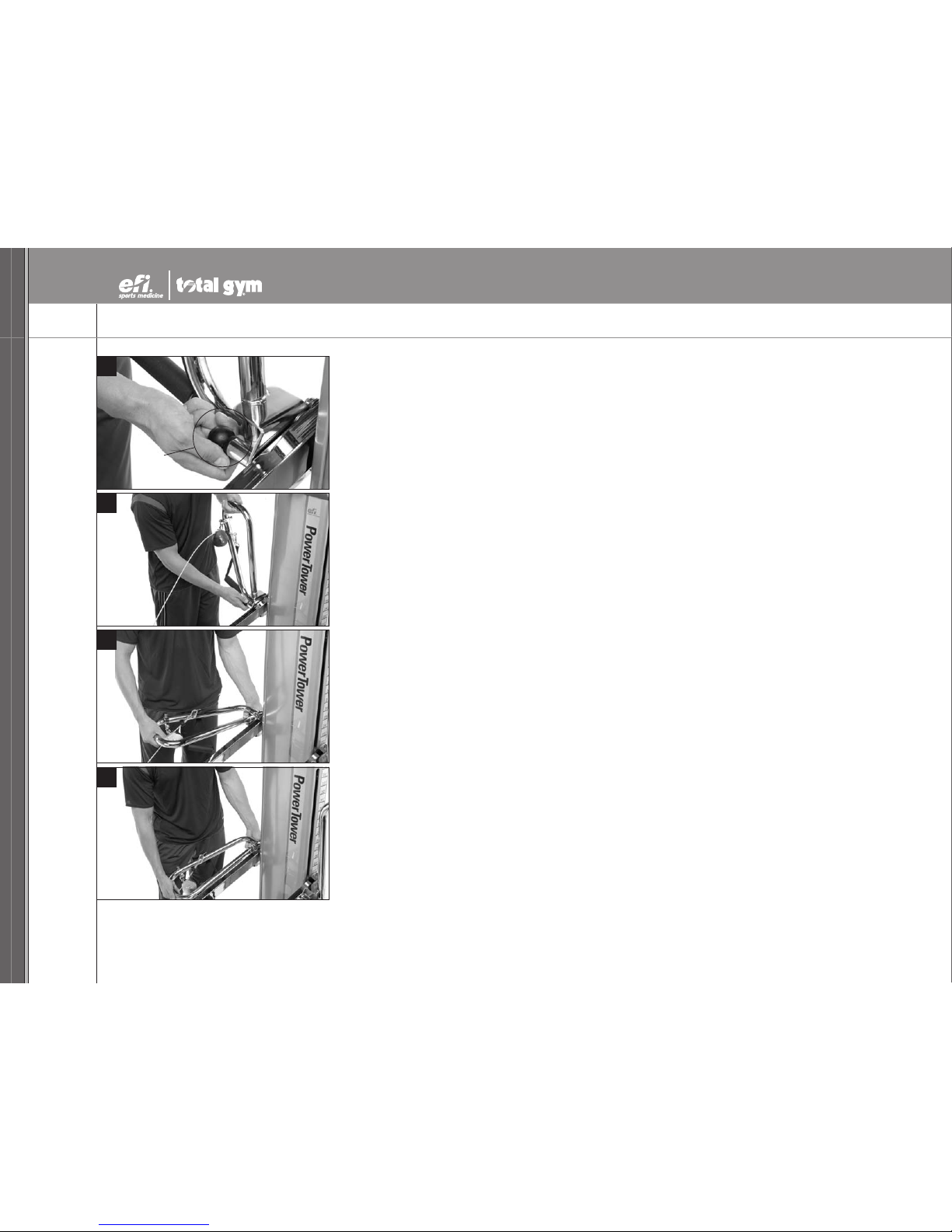
FOLDING FOOT HOLDER
46. Your PowerTower
TM
arrives with the Folding Foot Holder (E) in the down position.
47. Prior to use, rotate the Folding Foot Holder (E) to the upright position. Simply pull on the
retractable knob and raise the Folding Foot Holder (E) until the pin on the knob has engaged
the Upper Rail (X). Be sure the Folding Foot Holder (E) is securely mounted in the upright
position before proceeding.
48. Tobegin using the Folding Foot Holder (E), push in the center post snap button and raise the
Upper Foot Pad Assembly (E1).
49. Sit at the top of the Glideboard (G) and place your heels past the pads of the Lower Root Pad
Assembly (E2). Lower the Upper Foot Pad Assembly (E1) by pushing it down until the center
post snap button has re-engaged.
NOTE: Remember to return the Folding Foot Holder (E) to its original “lowered” position to avoid
interference with the Glideboard (G) during other exercises.
17
NOTE: Letters in (parentheses) refer to the PARTS IDENTIFIER on page 2 and/or the PARTS ASSEMBLY on page 3. Use as needed for clarification.
46
47
48
49

18
NOTE: Letters in (parentheses) refer to the PARTS IDENTIFIER on page 2 and/or the PARTS ASSEMBLY on page 3. Use as needed for clarification.
ADJUSTING THE RAIL ANGLE
50. To raise or lower the Rail (K, X) angle, stand alongside the Tower (A). Reach on top of the
Tower (A) to the Up/Down Switch (ZY). Micro switches at the upper and lower ranges of
resistance (4 degrees and 34 degrees respectively) halt movement at upper and lower
resistance limits. Any time you release the Up/Down Switch (ZY), movement ceases.
51. Any time you wish to use the glideboard free from the pulley cable assembly, simply unfasten
and release the center cable pulley snap hook.
52. Snap the center cable pulley to one of the LAT Bar pulley Locator brackets as shown.
50
51
52
This manual suits for next models
1
Table of contents
Other EFI Fitness Equipment manuals


Popular Fitness Equipment manuals by other brands

Rotfuß
Rotfuß W1 User and mounting manual

Hammer
Hammer Ergometer COMFORT XTR manual

Adidas
Adidas ADBE-10346 Assembly & user instructions

Ropeflex
Ropeflex IBEX-RX2300 Assembly & instruction manual

SPRI
SPRI Active Therapy Shoulder Pulley Setup, Workout Tips and Care & Safety Guide

S.R.Smith
S.R.Smith SWIM-N-DUNK & COMMERCIAL BASKETBALL GAMES Assembly and installation instructions


