manuals.online logo
Brands
  1. Home
  2. •
  3. Brands
  4. •
  5. EFI
  6. •
  7. Fitness Equipment
  8. •
  9. EFI GTS User manual

EFI GTS User manual

GTS®OWNER’S GUIDE
OWNER’S GUIDE GTS®
800 541 4900 EFISPORTSMEDICINE.COM
GTSOwnGuide_cover_jan08.qxp 1/18/08 11:23 AM Page 3
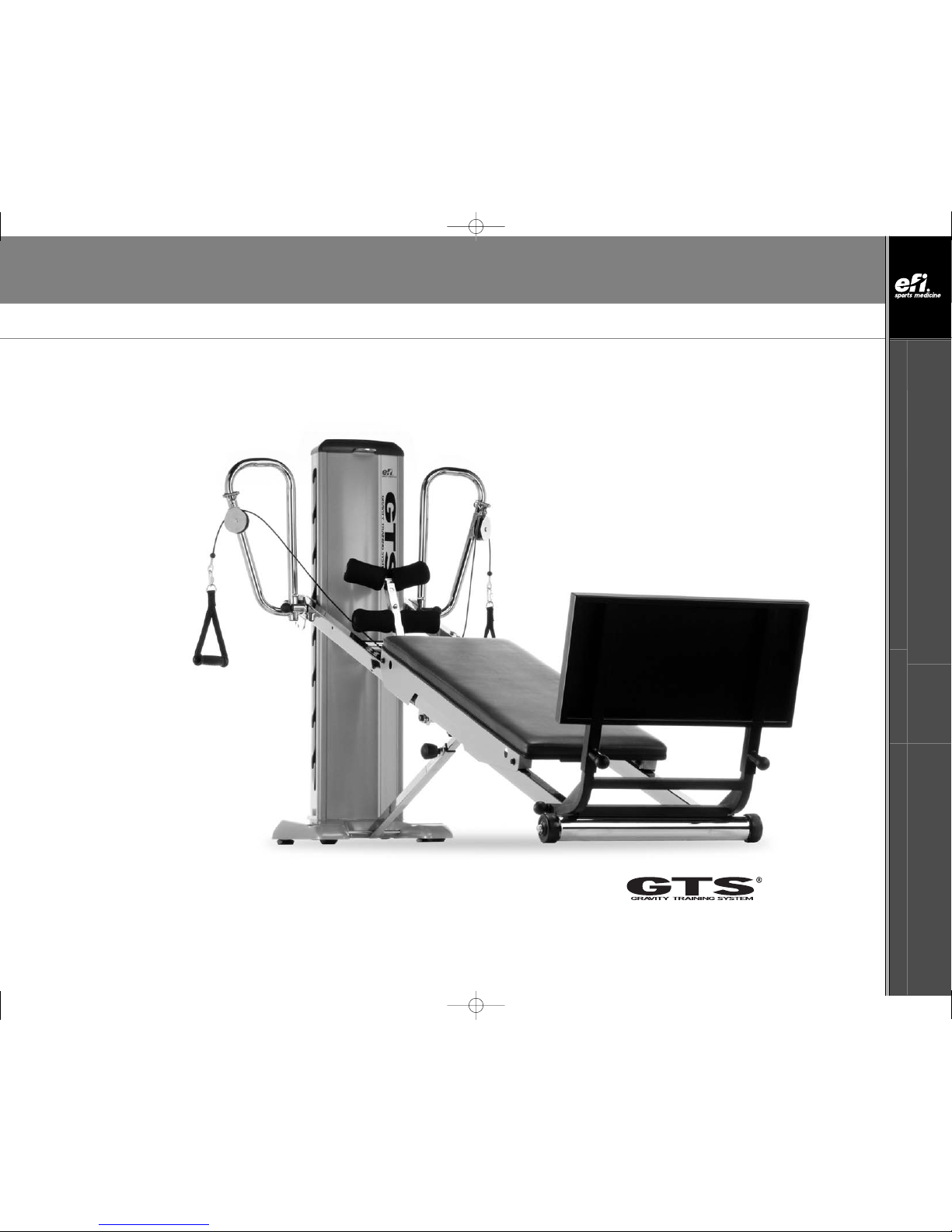
Thank you for purchasing GTS®,the center of the comprehensive GRAVITYSystem®.Your GTS is an
investment that will enhance your business and your life year after year.
Please read and save your Owner’s Guide so that you may refer to it in the future.
Your GTS®arrives with very little required in the way of assembly. Simply follow this Guide and your
GTS®will be operational.
In this Guide you will find tips about GTS and its component parts, operation, maintenance and care.
Additionally, you will find safety tips and precautions to help ensure your safety and the safety of your
clientele in a commercial setting. Also included is a description of your warranty information.
If during the course of using the GTS you have any questions about the product or you requireparts or
service, please write, email or call us at the address or phone number listed below.
Our goal is to supportyour success through the GRAVITYSystem®,and we stand ready to help you every
step of the way.
Sincerely,
President/CEO
efi Sports Medicine
7755 Arjons Drive
San Diego, CA 92126
U.S.A. area code (858) 586-6080
800 541 4900 toll-free inside U.S.A.
[email protected]
CAUTION: As with any exercise program, participants should consult a physician before starting a
workout on GTS.
CONGRATULATIONS
GTSOwnGuide_cover_jan08.qxp 1/18/08 11:23 AM Page 4
C
INSET 1(REAR TOWER VIEW)
W
X(see INSET 8)
T
B(on back of Tower; see INSET 1)
E(see INSET 3)
A. Tower
B. Tower Top Handle
C. Tower Pulley Pocket
D. Tower Lock Pin
E. Folding Foot Holder
E1. Upper Foot Pad Assembly
E2. Lower Foot Pad Assembly
F. Glideboard “D” Ring
G. Glideboard
H. Telescoping Squat Stand
I. Folding Platform
J. Lower Rail Base
K. Lower Rails
L. Glideboard Wheel Housing
M. Support Strut Knob
N. Upper Rails
O. SupportStrut
O1. Gas Spring (see inset 6)
O2. Curved Crossbar (see inset 6)
P. Rubber Feet
Q. Tower Base
R. Tower Level Hooks
S. Tower Back Handle
T. Molded Handles
U. Padded Crossbar (see inset 6)
V. Rectangular Bushings
W. Dynamic Arm Pulley System
X. Pulley Locator Brackets
Y. Lateral Adjustable Training
(LAT) Bars
Z. Tower Crossbar (see inset 9;
Tower Crossbar connects the Rails
through the Tower; LAT Bars not shown)
Y
C(on top of Tower; see INSET 1)
INSET 8
INSET 7 (REAR TOWER VIEW)
INSET 3
B
PARTS IDENTIFIER - GTS-03
V
E1
E2
F
S
D
F(see INSET 4)
INSET 4
Vsee INSET 7)
S(On back of Tower; see INSET 5)
INSET 5(REAR TOWER VIEW)
U(see INSET 6)
O2
INSET 2
INSET 6
INSET 9
D(see INSET 2)
^
G
A
Q
^
^
H
J
I
K
M
^ ^ ^^
P
N
O
L
R
Z
^
^
When parts are referenced throughout this guide,
corresponding letters from this PARTS IDENTIFIER page
arealso listed. For example, when “Tower” appears within
this guide, (A) will appear behind “Tower” as a cue to refer
back to this page if needed.
U
01
X
^
O1 (see INSET 6)
O2 (see INSET 6)
^
^
GTS®OWNER’S GUIDE
OWNER’S GUIDE GTS®
800 541 4900 EFISPORTSMEDICINE.COM
1
NOTE: Letters in (parentheses) refer to the PARTS IDENTIFIER on page 1 and/or the PARTS ASSEMBLY on page 2 Use as needed for clarification. GTS®OWNER’S GUIDE
NOTE: Letters in (parentheses) refer to the PARTS IDENTIFIER on page 1 and/or the PARTS ASSEMBLY on page 2 Use as needed for clarification.
NOTE: Letters in (parentheses) refer to the PARTS IDENTIFIER on page 1 and/or the PARTS ASSEMBLY on page 2. Use as needed for clarification.
2
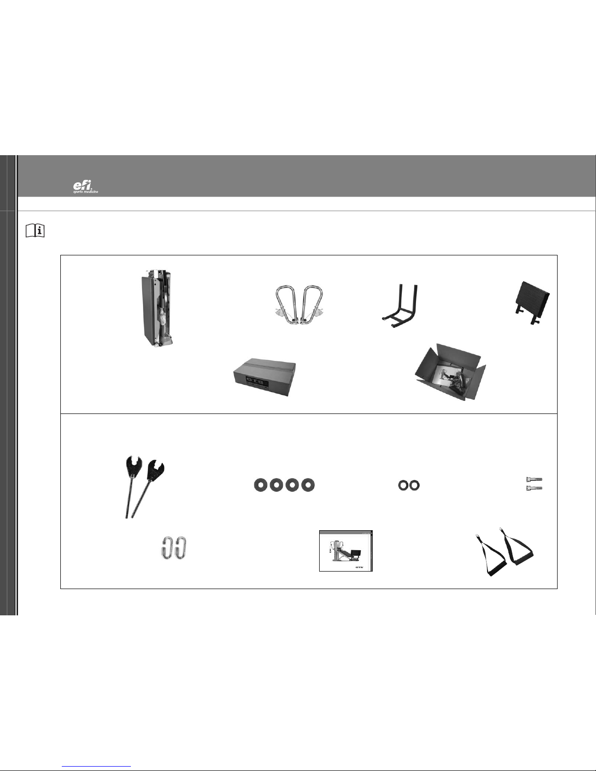
PARTS ASSEMBLY - GTS
Your GTS arrives with some assembly required.
HARDWARE PACKET CONTENTS
Tower, Rail &
Glideboard Assembly
BOX CONTENTS
LAT Bars &
Dynamic ArmPulley System Folding Platform Telescoping Squat Stand
Empty Spacer Box One Hardware Packet Box
Molded Handles (2)GTS Owner’sGuide (1)
Quick Links (2)
Socket Head Screws (2)Chrome Washers (2)Bronze Washers (4)
Wrenches (2)
4
GTS®OWNER’S GUIDE
OWNER’S GUIDE GTS®
800 541 4900 EFISPORTSMEDICINE.COM
3
NOTE: Letters in (parentheses) refer to the PARTS IDENTIFIER on page 1 and/or the PARTS ASSEMBLY on page 2 Use as needed for clarification.
1
2
3
6
SET UP - GTS
Remove your GTS from the box. Stand the GTS upright. Never turn your GTS
on its side because it will cause the gas spring to engage. Assemble and
use the GTS on level ground.
WARNING: Only install and use the GTS on a firm level surface. Minimum
floor space required for operation is 3.5 ft. x 9.5 ft [1 x 3 meter] of area.
SET UP - GTS: UNFOLDING
1. Stand to the side of your GTS with your right hand on the Glideboard
and your left hand on the Tower Lock Pin (D).
2. Disengage the Tower Lock Pin.
3. Store the Tower Lock Pin horizontally in the Lock Pin Bracket on the
SupportStrut (O) as shown.
4. Turn Support Strut Knob counter clockwise to loosen. Pull knob out and
hold until it disengages.
5. Place your left foot on the Tower Base (Q). Still holding the Support
Strut Knob, gently lift and pull the Lower Rails (K) away from the
Tower Base.
HELPFUL HINT: You can use your right foot to give a push on the
Lower Rail Base (J).
6. Continue pulling the Lower Rail Base (J) away from the Tower Base
until the GTS forms an “A” frame as shown. 5
NOTE: Letters in (parentheses) refer to the PARTS IDENTIFIER on page 1 and/or the PARTS ASSEMBLY on page 2. Use as needed for clarification.
4
7
9
11
13
SET UP - GTS: UNFOLDING (CONTINUED)
7. Hold the Padded Crossbar (U) with your right hand.
8. Hold the Tower (A) with left hand, while continuing to hold the
Padded Crossbar as shown.
9. Allow the Rails (K, N) to unfold away from the Tower until
the Rails are fully extended. IMPORTANT: Continue holding the
Tower and Padded Crossbar in place.
10. Grasp the Curved Crossbar (O2) or the Rail with your right hand
and raise Rails to Level 3 while pulling the Tower forward until the
Tower Crossbar (Z) sits securely in the Tower Level Hook (R).
11. Tilt Tower slightly backwards until the Support Strut Knob (M) pops
into position. Tighten Support Strut Knob by turning clockwise.
IMPORTANT SAFETY REQUIREMENT:SupportStrut Knob MUST be
engaged and tightened while GTS is unfolded or in use.
CAUTION: To avoid damage to your GTS, the Support Strut Knob
must be loosened and disengaged when folding.
REPOSITIONING GLIDEBOARD
12. To reposition the Glideboard (G) for use, stand or kneel beside the
Glideboard. First lift and pop one side of the metal Glideboard Wheel
Housing (L) away from the Rails. The other side of the Glideboard
should be free. NOTE: The Wheel Housing may feel tight.
13. Lift the Glideboard off the rails to reposition. Disengage the
Glideboard. Move the Glideboard about 6 inches up the Rails toward
the Tower until the metal stop on the underside of the Glideboard
rests above the rubber bumper on the Lower Rail. Lower the
Glideboard back into place.
8
10
12
Padded
Crossbar
rubber
bumper
metal stop
GTS®OWNER’S GUIDE
OWNER’S GUIDE GTS®
800 541 4900 EFISPORTSMEDICINE.COM
5
NOTE: Letters in (parentheses) refer to the PARTS IDENTIFIER on page 1 and/or the PARTS ASSEMBLY on page 2 Use as needed for clarification.
14
16
18
15
17
INSTALL LAT BARS
14. Raise the Rails (K, N) to Tower (A) level 5 or 6 to easily assemble
the LAT Bars.
15. SAFETY TIP: Ensurethat the Support Strut Knob (M) is engaged and
tight.
16. Your GTS arrives with shipping sleeves on the ends of the Tower
Crossbar (Z). The shipping sleeves serve one purpose: to protect the
Tower Crossbar during shipping.
17. To remove the first shipping sleeve, face the back of the
Tower and take the two supplied Wrenches (supplied in Hardware
Packet), one in each hand.
NOTE: For easiest assembly, keep the Tower Crossbar centered
throughout the assembly process with each end extending about
equal distance from the Tower.
18. Apply both Wrenches to the Nyloc Nuts on each side of the Tower
Crossbar. Facing the Tower back, use one Wrench to immobilize the
right Nyloc Nut while turning the left Nyloc Nut counter clockwise
with the other Wrench.
NOTE: Letters in (parentheses) refer to the PARTS IDENTIFIER on page 1 and/or the PARTS ASSEMBLY on page 2. Use as needed for clarification.
6
19
21
23
20
22
INSTALL LAT BARS (CONTINUED)
19. Remove the Nyloc Nut, Chrome Washer and the large Bronze
Washer. Set them aside.
20. Remove the first shipping sleeve by pulling it away from the
Tower Crossbar (Z). Set the first shipping sleeve aside.
21. To remove the remaining shipping sleeve, immobilize the exposed
end of the Tower Crossbar by applying one of the Wrenches to
the notch.
22. Use the other Wrench to loosen the remaining Nyloc Nut by turning
it counter clockwise.
23. Hold the Upper Rail (N) with one hand. Remove the second
shipping sleeve by pulling away from the Tower Crossbar with the
other hand. Set the shipping sleeve aside. You may discard the
shipping sleeves or retain them in the event you need to ship your
GTS in the future.
Now that the shipping sleeves have been removed, you are ready to
attach the first LATBar (Y).
GTS®OWNER’S GUIDE
OWNER’S GUIDE GTS®
800 541 4900 EFISPORTSMEDICINE.COM
7
NOTE: Letters in (parentheses) refer to the PARTS IDENTIFIER on page 1 and/or the PARTS ASSEMBLY on page 2 Use as needed for clarification.
25
24
26 27
INSTALL LAT BARS (CONTINUED)
POSITION THE LAT BARS - PHASE 2
24. To position the first LAT Bar (Y) for mounting, make sure the
long, vertical side of the LAT Bar aligns closest to the Tower (A).
NOTE: Six holes face the back of the GTS. The black knob is
nearest the Glideboard (G).
25. Retrieve the large Bronze Washer. Slide it onto the LAT Bar Cylinder.
26. Stand beside the Tower and align the LAT Bar Cylinder
with the Tower Crossbar (Z). Slide LAT Bar Cylinder onto the
Tower Crossbar until it is securely seated on the Upper Rail (N).
Tower Crossbar threads are exposed through LAT Bar Cylinder.
27. Rotate the LATBar to hang upside-down until the other LATBar
is installed.
Install other LAT Bar by repeating steps 24-27. Then go to
step 28 to position the LAT Bars and finish installation.
Bronze Washer
Black Knob
upside
down
NOTE: Letters in (parentheses) refer to the PARTS IDENTIFIER on page 1 and/or the PARTS ASSEMBLY on page 2. Use as needed for clarification.
8
28
30
32
29
31
INSTALL LAT BARS (CONTINUED)
POSITION THE LAT BARS - PHASE 2 (CONTINUED)
28. Retrieve the Chrome Washer. Slide it onto the end of the Tower
Crossbar (Z) that extends beyond the LAT Bar Cylinder.
29. Attach and finger-tighten the Nyloc Nut onto the Tower Crossbar
with the other hand.
30. Press against the Nyloc Nut to push the Tower Crossbar until it lies
flush against the LAT Bar Cylinder.
Repeat steps 28-29 to the other LAT Bar (Y).
ATTACH THE LAT BAR BRACKET - PHASE 3
For steps 31 - 34, utilize parts found in the Hardware Packet. Contents of
the Hardware Packet are shown on the bottom of page 2.
31. Raise the LATBar to the Pull-up position by pulling the retractable
knob on the LAT Bar. Remove the remaining contents from your
Hardware Packet.
32. First, place the small Chrome Washer on the Socket Head Screw.
Then place a small Bronze Washer on top of the Chrome Washer.
Chrome Washer
Tower Crossbar
GTS®OWNER’S GUIDE
OWNER’S GUIDE GTS®
800 541 4900 EFISPORTSMEDICINE.COM
9
NOTE: Letters in (parentheses) refer to the PARTS IDENTIFIER on page 1 and/or the PARTS ASSEMBLY on page 2 Use as needed for clarification.
33
34
35
33. Place the Socket Head Screw on the end of the Wrench. With one hand, feed the Socket Head Screw partially
through the elongated slot. With the other hand slide another small Bronze Washer between the Rail and LAT
Bar, as shown. Feed the Socket Head Screw through washer and tighten it to the rail. Repeat on the other side.
Use both Wrenches to tighten the Nyloc Nuts on the Tower Crossbar (Z) until the nut is flush with the end of
the shaft. Next, tighten the Socket Head Screw until it begins to get tight. Then loosen the screw 1/8 turn for
proper LAT Bar mobility. The LAT Bars should rotate from the Pull-up Position to the Folding Position slowly by
their own weight. Positions shown on the following page.
34. Attach the Molded Handles (T) to the cable ends using the Quick Links found in the Hardware Packet.
With these steps (15 - 34) completed, your LAT Bars are assembled.
35.Store the center pulley, when not in use, in the Tower Pulley Pocket (C) located at the top of the Tower (A)
clearly marked by a placement label.
Socket
Head
Screw
Nyloc Nut
NOTE: Letters in (parentheses) refer to the PARTS IDENTIFIER on page 1 and/or the PARTS ASSEMBLY on page 2. Use as needed for clarification.
10
36
37
GTS OPERATION INSTRUCTIONS
ADJUST LAT BAR
36. To adjust the LAT Bars (Y), pull the retractable knob on the LAT Bar to disengage the LAT Bar from the
Upper Rail (N) and rotate LAT Bars to the desired position. Ensure that the pin on the retractable knob is
properly engaged before use.
LAT BAR ADJUSTS TO THREE POSITIONS
37. NORMAL USE: Parallel (upright) to the Tower (A), perpendicular to Rails (K, N).
38. PULL-UP POSITIONS: Angled upwards from the Rails.
39. FOLDING POSITION: Parallel to the Rails.
38
39
GTS®OWNER’S GUIDE
OWNER’S GUIDE GTS®
800 541 4900 EFISPORTSMEDICINE.COM
11
NOTE: Letters in (parentheses) refer to the PARTS IDENTIFIER on page 1 and/or the PARTS ASSEMBLY on page 2 Use as needed for clarification.
40
41
42
43
ADJUST RAIL ANGLE
To raise or lower the angle, stand alongside the Upper Rail (N), facing the Tower (A).
40. When you are raising the resistance level, lift from the Curved Crossbar (O2) or Rails (K, N) and slip the
Tower Crossbar (Z) into the desired Tower Level Hook (R). The higher the Rails are on the Tower, the higher the
resistance. Once the Tower Crossbar connects with the desired Tower Level Hook, lower the Rails and make sure
that Tower Crossbar is securely seated inside Tower Level Hook.
IMPORTANT: Be sure the Tower Crossbar is fully secured in the Tower Level Hook on both sides before use.
Always perform a visual and manual check before getting on the GTS.
41. When you arelowering the resistance level, lift the Curved Crossbar (O2) or Rails to disengage the Tower
Crossbar from the Tower Level Hook. Push the Tower back and lower the Rails to the desired level, then release
the Tower and it will rock forward. Once the Tower Crossbar aligns with the Tower Level Hook, pull the Tower
forwardand lower the Rails to ensurethe Tower Crossbar is securely seated.
ATTACH & DETACH DYNAMIC ARM PULLEY CABLE SYSTEM (W)
42. To attach the Dynamic Arm Pulley System to the Glideboard (G) connect the snap hook to the
Glideboard “D” Ring (F).
43. Tofree the Glideboardfrom the Dynamic ArmPulley System, simply unfasten and release the snap hook on
the pulley, then store the center cable pulley in the Tower Pulley Pocket (C).
NOTE: Letters in (parentheses) refer to the PARTS IDENTIFIER on page 1 and/or the PARTS ASSEMBLY on page 2. Use as needed for clarification.
12
44
46
48
45
47
FOLDING FOOT HOLDER (E)
44. Your GTS arrives with the Folding Foot Holder attached. Remove the
packing material.
45. To raise the Folding Foot Holder, simply pull it up until the knob
fully engages in the upright position.
46. To adjust the height of the Folding Foot Holder, push in the center
post snap button and raise the Upper Foot Pad Assembly (E1). This
allows individuals with longer feet to easily position themselves in
the Folding Foot Holder.
47. To begin using the Folding Foot Holder, sit at the top of the
Glideboard (G) and place your heels past the pads of the Lower Foot
Pad Assembly (E2).
48. If you have adjusted the Upper Foot Pad Assembly for easy
positioning, lower the Foot Pad Assembly by pushing it down until
the center post snap button has re-engaged.
NOTE: After you are finished with the Folding Foot Holder,
remember to pull the knob and lower it to avoid interference with
the Glideboardduring other exercises.
GTS®OWNER’S GUIDE
OWNER’S GUIDE GTS®
800 541 4900 EFISPORTSMEDICINE.COM
13
NOTE: Letters in (parentheses) refer to the PARTS IDENTIFIER on page 1 and/or the PARTS ASSEMBLY on page 2 Use as needed for clarification.
49
51
53
55
50
52
54
56
INSTALL FOLDING PLATFORM (I)
49. Face the Tower (A) and align the bottom of the Folding Platform
with the large outside holes on the Lower Rails (K) just above the
Lower Rail Base (J).
50. Slide the fixed pin into the large hole in the outside left Lower Rail.
You do not need to install the smaller pop-pin into its hole yet.
51.-52. While keeping the Folding Platform rotated toward the Tower, pull
the retractable pin on the right side and move the pin over the hole.
Release the pin.
Rotate the Folding Platform back until the smaller pin on the left
rail engages completely.
INSTALL TELESCOPING SQUAT STAND (H)
53. Align the Telescoping Squat Stand over the Folding Platform struts
until the Telescoping Squat Stand pins contact the top of the
Folding Platform struts.
54. Toadjust the height of the Telescoping Squat Stand, pull both
retractable pins simultaneously and raise or lower the Telescoping
Squat Stand until both pins engage in one of the three adjustment
sets of holes in the Folding Platformstruts.
PULLEY LOCATOR BRACKETS (X)
55-56. The Pulley Locator Brackets are designed to adjust easily. Stand
behind the Tower.Pull back on the black knob of the Pulley Locator
Bracket. Then, move the Pulley Locator Bracket to the desired position
on the LATBars (Y) and allow the pin to engage in the desired hole.
When adjusting the Pulley Locator Bracket around the bends, rotate
the pulley inward to make the turn.
LAT Bar Positions
1
2
34
5
6
Fixed Pin
NOTE: Letters in (parentheses) refer to the PARTS IDENTIFIER on page 1 and/or the PARTS ASSEMBLY on page 2. Use as needed for clarification.
14
57
59
61
63
58
60
62
64
FOLDING AND STORAGE
57. The GTS is easily folded for storage. Whenever you move or store the
GTS, fold the Telescoping Squat Stand (H) and Folding Platform (I)
toward the Glideboard (G). Follow the instructions below.
TO FOLD
58. Pull the Folding Platform left side retractable pin [as you face the
Tower (A)] while pushing the Telescoping Squat Stand forward until
the retractable pin locks in place in the folded position against the
Glideboard.
59. Lower the Folding Foot Holder (E). Pull the Folding Foot Holder knob
on the inside of the right rail to rotate the Folding Foot Holder to
the down position.
60. Attach the center pulley snap hook [located on the Dynamic ArmPulley
System (W)] to the 1/4 rings on the upper Support Strut. The pulley and
cable should be underneath the Padded Crossbar (U).
61. Adjust the Pulley Locator Brackets (X) to the fourth position on the
LATBars. Next, lower the LATBars (Y) to the folding position
(parallel to the rails).
62. With one hand holding on to the Tower and one hand on the Curved
Crossbar (O2), disengage the Rails from the Tower Hooks (R) and
lower the Rails slowly toward the Tower Base (Q) to the folding
position below the first Tower Hook (R).
63. Continue holding the Tower while you unscrew and disengage the
Support Strut Knob (M) by pulling it out.
64. HINT: Rock the Tower backward to help loosen the Support Strut
Knob. Once the SupportStrut Knob has disengaged, pull the Tower
forward to its full upright position.
IMPORTANT: You must disengage the Support Strut Knob during
folding to avoid damage to your GTS.
3
2
1
4
5
6
GTS®OWNER’S GUIDE
OWNER’S GUIDE GTS®
800 541 4900 EFISPORTSMEDICINE.COM
15
NOTE: Letters in (parentheses) refer to the PARTS IDENTIFIER on page 1 and/or the PARTS ASSEMBLY on page 2 Use as needed for clarification.
65
67
69
71
66
68
70
72
FOLDING AND STORAGE (CONTINUED)
65.-66. While continuing to hold the Tower (A), grasp the Padded
Crossbar (U), then move into position to pull the Rails (K,N) up
and toward the Tower.
67. Pull the Rails up and toward the Tower until the rails form an
A-frame.
68.-69. Continue pulling the Rails toward the Tower until the Lower Rail
Base (J) rests on the Tower Base (Q) and the GTS stands upright.
You can use your foot to push the Rail Base onto the Tower Base.
70. Insert the Tower Lock Pin (D) to secure the GTS in the upright
position.
IMPORTANT:Check to make surethe SupportStrut Knob (M) has
re-engaged then turn the knob clockwise to tighten it.
71. Hang the Molded Handles (T) on the knobs of the Telescoping Squat
Stand (H) so that they are out of the way. To avoid cable damage,
make surethe Dynamic ArmPulley System (W) remains free from
the center hinge, floor or transport wheels.
Tounfold the GTS and return it to use, Follow the unfolding
directions at the beginning of this guide.
TO MOVE THE GTS
72. Stand behind the Tower,grasp the Tower Top Handle (B) and lean
the Tower back toward you. You can now wheel the GTS, similar to
how you would move a hand cart.
NOTE: Letters in (parentheses) refer to the PARTS IDENTIFIER on page 1 and/or the PARTS ASSEMBLY on page 2. Use as needed for clarification.
16
73
75
77
PROPER SEATED FORWARD SEQUENCE WITH DYNAMIC ARM
PULLEY SYSTEM (W) ATTACHED TO THE GLIDEBOARD (G)
73. Grasp both Molded Handles (T) in the hand closest to the Tower (A)
as you stand to one side of the GTS.
74. Straddle the Glideboard facing the Squat Stand and separate
Molded Handles into each hand. Ensure cables are not crossed.
75. Pull the Glideboard (G) up the Rails (K,N) and sit in the proper
position for the specific exercise you will perform. If you are
performing a sitting exercise, sit at the top of the Glideboard.
PROPER LYING SUPINE SEQUENCE WITH DYNAMIC ARM
PULLEY SYSTEM (W) ATTACHED TO THE GLIDEBOARD (G)
76. If the exercise requires you to lie back, pull the Glideboard up the
Rails and sit towards the bottom edge.
77. When lying on your back, be sureyour head is supported on the
Glideboard (G). SECURELY TIE-UP LONG HAIR to avoid getting
caught in moving parts. If the Glideboard travels all the way to the
top or bottom of its rolling distance during the exercise, adjust your
body up or down on the Glideboard, so that the Glideboard does not
top or bottom out during the exercise.
74
76
GETTING STARTED
KEEP HANDS, FINGERS, HAIR, ETC. AWAY FROM ALL MOVING PARTS.
Participants using GTS should wear athletic shoes and comfortable lightweight clothing. Long hair should be tied back to avoid contact with the center pulley, center
hinge or rollers. Before use, check to ensure that all GTS parts are in place and working properly and the Support Strut Knob (M) is engaged.
Begin the exercise program at a level where you or your session participants can perform the exercise with good form throughout the exercise set. As fitness levels
progress, raise the incline to increase the load and level of resistance. Build gradually to higher resistance levels, always staying aware of form and control.
Control the speed of movement during cable exercises and control the Glideboard at all times, particularly when getting on or off the GTS. The following coaching
tips will help you or your session participants stabilize the Glideboard as you approach the unit for mounting in various positions.
GTS®OWNER’S GUIDE
OWNER’S GUIDE GTS®
800 541 4900 EFISPORTSMEDICINE.COM
17
NOTE: Letters in (parentheses) refer to the PARTS IDENTIFIER on page 1 and/or the PARTS ASSEMBLY on page 2 Use as needed for clarification.
79
82
84
PROPER ANCHORING SEQUENCE WITH DYNAMIC ARM PULLEY
SYSTEM (W) ATTACHED TO GLIDEBOARD (G)
78. Grasp Molded Handles (T), then make a fist and place your knuckles
at the top of the Glideboard to anchor it in place. Now it is safe to
sit, straddle or kneel on the Glideboard.
79. When kneeling on the Glideboard, place knees one at a time just
behind your fists as you face the Tower.
80. Slowly move to the starting position of the exercise and begin by
using controlled movements.
PROPER LATERAL ANCHORING SEQUENCE WITH
DYNAMIC ARM PULLEY SYSTEM (W) ATTACHED TO GLIDEBOARD (G)
81. Stand to the side of the Glideboardand grasp the Molded Handle on
the opposite side with the hand closest to the Tower (A).
82. Place the hand that holds the Molded Handle knuckles-down at the
top of the Glideboard to anchor it in place. Now it is safe to sit or
kneel on the Glideboard.
83. IMPORTANT: Maintaining your anchored fist, kneel on the Glideboard
with a WIDE BASE OF SUPPORT.Never attempt this position with
knees together.
84. Slowly remove your anchored fist from the Glideboard, keeping your
body weight evenly distributed through both knees. Kneel upright and
grasp Molded Handle with both hands.
NOTE: Reverse this sequence when dismounting from a kneeling
lateral position.
Always control the Glideboard while mounting or dismounting your GTS.
Do not exceed 650 pounds (295 kg) of total weight-bearing on GTS,
including body weight, weight bar and added weights.
Maximum user body weight is 350 pounds (159 kg).
WARNING
!
78
80
81
83 Wide Base
of Support
NOTE: Letters in (parentheses) refer to the PARTS IDENTIFIER on page 1 and/or the PARTS ASSEMBLY on page 2. Use as needed for clarification.
18
Weekly
• Inspect Dynamic Arm Pulley System (W)
for wear or damage. If plastic outer cable
cover is compromised in any way, replace
damaged cable.
• Wipe down rails with dry cloth and use chrome pol-
ish when necessary to remove dust buildup.
HINT: As an alternative to polish, steel wool (0000
grade) and cleaner can be gently used to remove
build-up from the rails and rollers.
• Clean and dry all surface areas for aesthetics.
• Check all Screws, Fasteners and Knobs to ensure
that they are installed correctly and tightened.
a. LAT Bar screws
b. Folding Foot Holder (E) screws
c. Pull Pins/Retractable Knobs
d. GlideboardWheel Housings (L) on the
Glideboard
e. Shoulder Bolt on the Rail Center Hinge
• Check for ease of use when changing levels
on the GTS Tower (A). Reportany difficulty in
changing levels or seating the Tower Crossbar in the
Tower Level Hooks. Discontinue use if customers
cannot seat the Rails (K, N) properly and contact
efi Sports Medicine Account Coordinator.
• Visually and functionally check all pulleys for
smooth operation. Clean as needed.
• Check all pads, fabric or foam for wear and replace
as needed.
a. Folding Foot Holder pads
b. Glideboard upholstery
c. Molded Handles (T)
MAINTENANCE AND CARE
Your GTS will offer your health and fitness or wellness
facility and your clientele years of easy operation if
you follow these simple tips for maintenance and
care. With periodic cleaning, moving parts and rolling
surfaces will maintain their smooth function.
Daily
•Ensure that Support Strut Knob (M) is secure before
use (tighten clockwise).
•Ensurethat the Tower Crossbar (Z) is securely
seated into Tower Level Hooks (R) after each level
change.
• Wipe down padded surfaces with
antibacterial cleanser after each use.
• Move Glideboard(G) up and down Rails to ensure
smooth tracking. If Glideboard does not roll
smoothly,clean Rails and rollers thoroughly with
DRYcloth.
Monthly
• Remove all Glideboards for visual inspection of
rollers/wheels. Clean any debris accumulated on
the roller assembly.
• Ensure that the rubber stoppers located on the
Lower Rail (L) are tight. Replace damaged
stoppers.
• Inspect and clean rubber pads located beneath the
tower base to ensure good “gripping” on wood
floors.
• Check function of the Support Strut Knob.
For safety, secure all Support Strut Knobs clockwise
before use.
• Visually inspect all Glideboards for tearing or
punctures.
• Check all additional accessories for proper function
and wear.
•For long-termstorage or high humidity environ-
ments, WD40 can be applied to a cloth and wiped
lightly to all chrome surfaces. Wipe dry before use.
•Check Gas Spring (O1) for lift assist without noise
or stiffness. Replace if needed. Call efi Sports
Medicine for the parts and replacement procedure.

Other manuals for GTS

1

Other EFI Fitness Equipment manuals

EFI Total Gym GTS Gravity User manual

EFI

EFI Total Gym GTS Gravity User manual

EFI GTS User manual

EFI

EFI GTS User manual

EFI POWER TOWER User manual

EFI

EFI POWER TOWER User manual

Popular Fitness Equipment manuals by other brands

Fluid E820 Fitness UBE owner's manual

Fluid

Fluid E820 Fitness UBE owner's manual

TOORX BRXOffice Compact manual

TOORX

TOORX BRXOffice Compact manual

Inspire ACB Assembly & operation manual

Inspire

Inspire ACB Assembly & operation manual

Matrix MABR1 manual

Matrix

Matrix MABR1 manual

Stamina 55-1531 Safety information

Stamina

Stamina 55-1531 Safety information

G-FITNESS TZ-6017 user manual

G-FITNESS

G-FITNESS TZ-6017 user manual

Accelerated Care Plus OMNISTIM FX2 CYCLE/WALK user manual

Accelerated Care Plus

Accelerated Care Plus OMNISTIM FX2 CYCLE/WALK user manual

BLK BOX 21-0122-0B Owner's manual & quick start guide

BLK BOX

BLK BOX 21-0122-0B Owner's manual & quick start guide

StormRed HURRICANE user manual

StormRed

StormRed HURRICANE user manual

XMark Fitness XM-9023 owner's manual

XMark Fitness

XMark Fitness XM-9023 owner's manual

Zonzini BUDDY Series Instruction and maintenance handbook

Zonzini

Zonzini BUDDY Series Instruction and maintenance handbook

Master POSEIDON user manual

Master

Master POSEIDON user manual

Everlast ELITE GYM user manual

Everlast

Everlast ELITE GYM user manual

Tumbl Trak Jr. Kip Bar Assembly & instruction manual

Tumbl Trak

Tumbl Trak Jr. Kip Bar Assembly & instruction manual

HMS S3096 Manual instruction

HMS

HMS S3096 Manual instruction

Titan Fitness RKTPBRv3 Operator's manual

Titan Fitness

Titan Fitness RKTPBRv3 Operator's manual

human care Diana II ELA Service manual

human care

human care Diana II ELA Service manual

Sunny Health & Fitness SF-BH620038 user manual

Sunny Health & Fitness

Sunny Health & Fitness SF-BH620038 user manual

manuals.online logo
manuals.online logoBrands
  • About & Mission
  • Contact us
  • Privacy Policy
  • Terms and Conditions

Copyright 2025 Manuals.Online. All Rights Reserved.