Efitron SOLAR30 User manual
Intelligent Solar Charge Controller
User s M anual
Please read this instruction carefully before using it.
This controller is a kind of intelligent and multifunctional solar
charge controller.These serial productsadopt customized LCDdisplay
screen, which makesthe operation onthe interface ratherconvenient.
All the controllingparameters can bereset exibly tosatisfy your dierent
needs. This controller has thefollowing features:
1Product introduction
Visual LCD graphic symbol
Brief key operation
Grade auto switchof system voltage
Intelligent PWM ChargingMode
Auto temperature compensation
Adjustable charging &discharging parameter
Settable working modesof loads
Accumulative function ofcharging & discharging AH
Protection for batteryback discharging
Protection for batterylow voltage
Overloading & short-circuitprotection
Battery reversed protection
Delayed auto restartafter overloading protection
2Installation Explanation
Installation
Get ready the related tools& cables. We suggest you choose the appropriate cables
2
to ensure the current density 4A/mm and this is good for reducing cable voltage
22
drop. Recommendation30A using 10mm cable50A using 16 mm cable.
Check whether installation
place accordswith the relative
safety rules.Pleaseavoid installing
and using thecontroller under
the following conditions:wet,
dusty places or places with
ammable and explosive gases.
Install the controller at the
vertical plane. Please refer to
chapter 5for more detailedinfo
about thespacing between the
installing holes. In order tomake
the controller havegood thermal
dissipation, pleasespare10cm
above & below the controller.
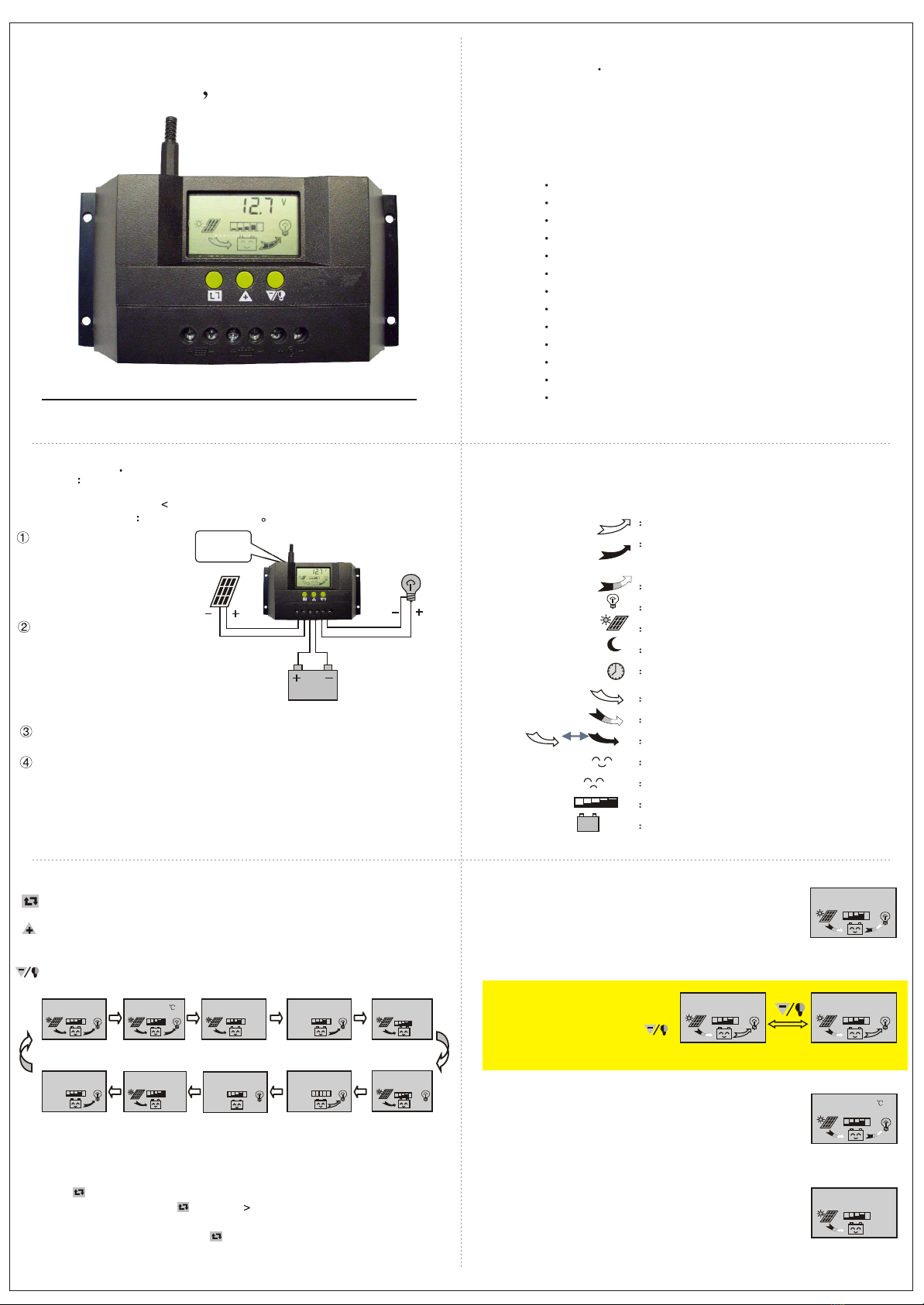
As shown as the right gure, connect the loads, battery and solar panels with the
controller in order. Pay attention to connect the loads, batteryand solar panels right.
Plug the external thermal sensor into the interface of the thermal-sensoron the left
of the controller.
Disassemble:To avoid the accident, please dismantle the solar panels, battery, loads
from the controller in order.
Attention:Connecting the battery reversed will not damage the controller, but will
cause safety risk on yourloads.
3. Operation
1. Explanation of LCD Graphic Symbol
stop supplying powerfor loads
supplying power forloads,
no current inload loop
having current inload loop
load icon
solar panels icon
load light controllingicon
load timing controllingicon
stop charging forbattery
charging for batteryat full speed
oat charging forbattery
normal working stateof system
abnormal working stateof system
battery capacity display
battery icon
2 . Explanation of button function:
:Interfaces circular toggling button. Use this button can realizethe toggling circularly
among the interfaces. The circular order is as follows: as shown asgure 1.
: Parameter adjusting'+'+ button. Besides, under parameter review condition, press
this button for over 5 seconds, and all the parameters willrecover to the ex-work
setting state.
:Parameter adjusting'-'button. Besides, at the main interface, this button can turnon
or turn o the load.
28
13.8
V
P V O F F
L O A D
V
O F F
990
A h
LO A D
999
A h
P V
13.0
V
24
h
L O A D O N
20.0
A
L O A D
Battery voltage
(main interface)
battery
temperature
load discharging
current
accumulative
generating AH
Load working
state
ceasing charging
voltage
low voltage
protection poin
accumulative
discharging AH
20.0
A
P V
solar panels
generating current
12.6
V
L O A D O N
recovery voltage
3. Parameter review and setting:
After the controller electries right, it will enter into the displayinginterface of
battery voltage. This interface is the main interface of thecontroller. P ress
buttonto go through the interfaces of the following parameters. Ifthe interface
can be reset, press button for long( 5 seconds, and the number on the
interface starts to icker), then it enters into the settinginterface of this parameter.
After nishing setting, press buttonfor long to exit the setting interface, and the
number stops ickering.
3.1 Battery voltage review
12.5
V
VV
As shown as the right gure, the displaying number is the
present battery voltage.
This interface is the main interface, and it shows the
charging & discharging state, battery capacity and
battery voltage.
3.2 Load ON/OFF controlling
At the battery voltage review
interface, you can press button
to turn on or turn o the load, while
this button does not have this function at other interfaces.
3.3 Environmental temperature review
As shown as the right gure, the displaying number is the
surrounding environmental temperature of the controller.
3.4 Review the generating current of solar panels
As shown as the right gure, the displaying number is the
generating current of solar panels.
27.0
A
P V
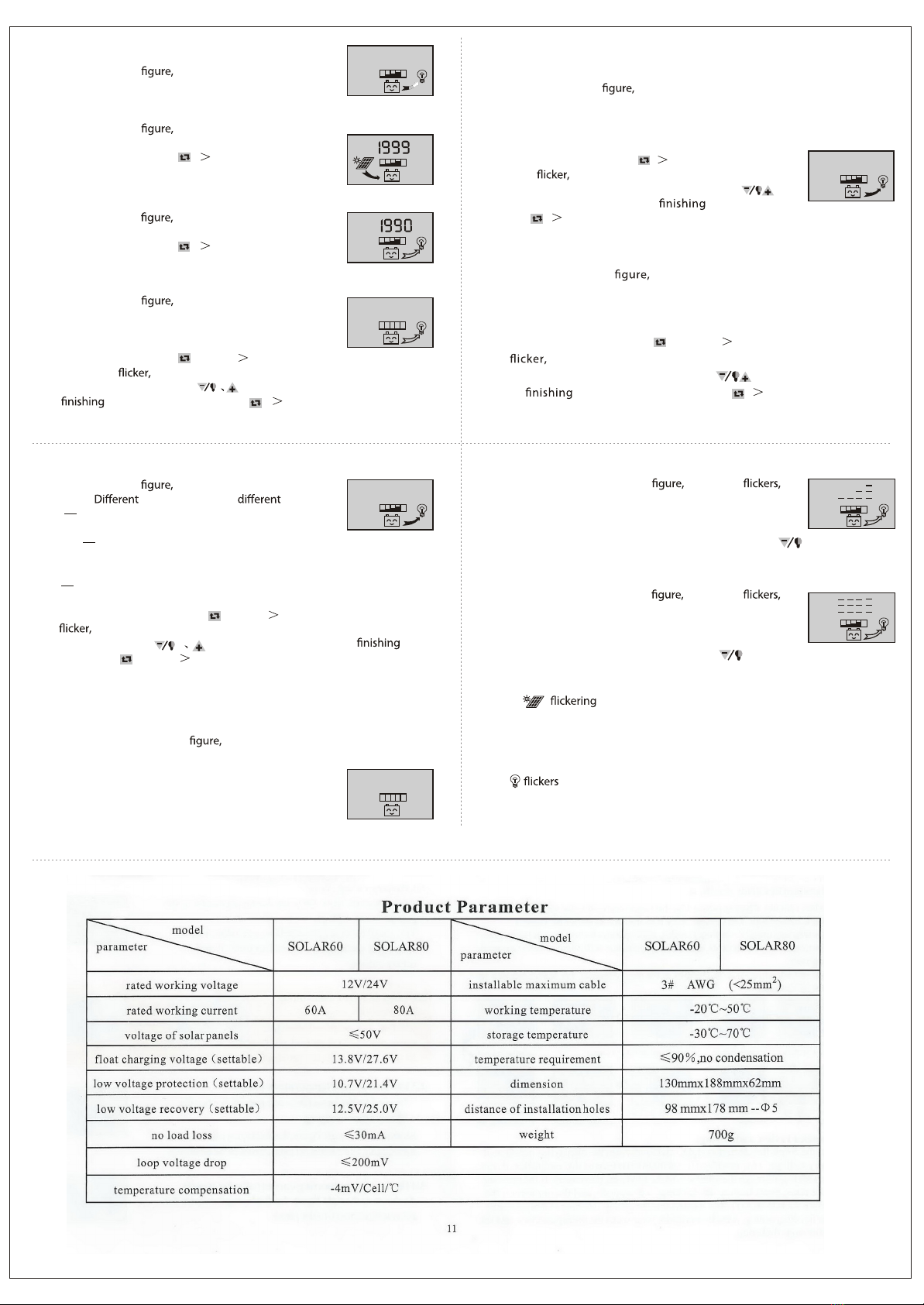
SOLAR30 12V/24V AUTO WORK
10.7
12.512.5
Be used for the temperature compensation when the
battery ceases charging.
1 2
3 4
56
Temperature
sensor
interface
Controller
Solar panelsDC load
Battery
28
As shown as the right the displaying number
is the load current.
3.5 The load current review
20.0
A
LO AD
As shown as the right the displaying number is the
accumulating generating AH of solar panels
At this interface, press button ( 5 seconds), and it can
clear accumulative generating AH.
3.6 Review and clearing the accumulative generating AH of solar panels
Ah
P V
3.7 Review and clearing load accumulative discharging AH
As shown as the right the displaying number is the
accumulative discharging AH of loads.
At this interface, press button ( 5 seconds), and it can
clear accumulative discharging AH.
Ah
LO AD
As shown as the right the displaying number is the
protection voltage. And if the battery voltage is lower than
this voltage, the controller will disconnect the load loop to
prevent the battery from over-discharging.
At this interface, press button for long( 5 seconds),the
number starts to and it means the controller enters into the interface ofsetting
the protection voltage.Use button to adjustthis parameter.
After setting, press button for long ( 5 seconds) to exit this interface
and the controller can store this setting number.
3.8 Review and setting low voltage protection function
V
LO AD
O F F
3.9 Review and setting recovering voltage for low voltage
condition
As shown as the right the displaying number is the
recovery number. After the controller enters into low voltage
protection state, and when the battery voltage recovers to
be higher than the recovering voltage, then the controller
will reconnect the load loop automatically.
At this interface,press button ( 5 seconds),thenumber
starts to and it means the controller enters into the
interface of setting the recovery voltage. Use button
to adjust this parameter. After setting, press
button ( 5 seconds) to exit this interface and the controller can storethis
setting number.
12.6
V
As shown asthe right thedisplaying number is thevoltage of ceasing
charging. When thebattery voltage reaches upto this voltage, the controller
will disconnect the chargingloop to prevent thebattery from o vercharging.
After th e battery voltage drops, the controller will reconnectthe chargingloop.
At this i nterface, pr ess button for long( 5 seconds),the number starts
to and it means the controllerenters into the interfaceof setting the
voltage ofceasing charging. Use button to adjust thisparameter.
After setting, pressbutton for long ( 5 se conds) to e xit thi s
interface and the controllercan store this settingnumber.
3.10 Review and setting the voltage of ceasing charging
As shown as the right it is the reviewing surfaceof the
load mode. numbers represent load mode.
3.11 Review and setting the load mode
24
h
LO AD O N
24h indicating normal mode, loads are under the condition
of supplying power without breakdown;
1h~23h indicating delayed mode of light control, loads start
to supply power after darkand shun downafter working forthe delayed
setting hours
Oh indicating light control, loads start to supply power after dark andstop
working after dawn.
At this interface, press button for long( 5 seconds),the number starts to
and it means the controller enters into theinterface of setting the load
modes. Usebutton to adjustthis parameter.After setting,
press button for long( 5 seconds)to exit this interface and the controller
can store this setting number.
Breakdown & disposal
If the screen shows as the right it means thebattery
voltage is lower than the protection voltage. The controller
enters into the low voltage protection state and the load loop
disconnects. Use the solar panels or charger to charge for the
battery. When battery voltage recovers to the protection
voltage, the controller will recover to supply power for load,
and enter into the working state.
Low voltage protection & disposal:
V
If the screen shows as the right and thelight it
mean the current of the load loop is 1.2 times fothe rated current
within 3 seconds, and the controller is at overloading state.After
removing some loads, the controller will supply power to the
loads automatically within seconds, or you can press button to recover the
power supply compulsively.
Overloading protection & disposal:
If the screen shows as the right and thelight it
meanstherehappensshort-circuitintheloadloop,andthecontroller
is at short-circuit protection state. Please check whetherthe loads
are damaged and whether the connecting cables are short-circuit.
After eliminating the breakdown, press button to recover the power supply
for the loads.
Short-circuit protection & disposal:
Breakdown & disposal of solar panels:
Sign means the controller do notdetect the existence of solar panels.
Please check whether the connecting with the solar panels is nigood condition, and
check whether the cables connecting the solar panels and the controller are i n
open-circuit condition.
If when you turn onthe load, it means the starting impulsion current is
more than twice of the rated working current. Please restart the controllerfor times.
Other exceptional conditions: Please contact the distributor or manufacturer.
Load impulsion breakdown:
10.7
10.6
7 8
9 10
11
This manual suits for next models
2
Other Efitron Inverter manuals


Popular Inverter manuals by other brands

Emergi-Lite
Emergi-Lite EMIU-125W instruction manual

Veichi
Veichi SI30 series manual

Xilinx
Xilinx EH600 A Series user manual

Siemens
Siemens HiPath 500 Installation operation & maintenance

Briggs & Stratton
Briggs & Stratton Standby Generator Systems Installation & start-up manual

dolycon
dolycon CT112 Series user manual


CRX
CRX CRX332 instruction manual

Jiangsu GoodWe Power Supply Technologu Co.
Jiangsu GoodWe Power Supply Technologu Co. SS series user manual

AIMS Power
AIMS Power PWRI18012S instruction manual

Huawei
Huawei SUN2000-8KTL user manual

SOLIS
SOLIS RHI-3P10K-HVES-5G installation guide

ENC
ENC EN600PV Series user manual