dolycon CT112 Series User manual


Solar Pump Inverter Content
Content
Safety precautions……………………………………………………………………1
Chapter 1 System Introduction ……………………………………………………6
Chapter 2 Solar Pump Inverter ……………………………………………………7
Chapter 3 System Collection Diagram …………………………………………15
Chapter 4 Function Parameters …………………………………………………27
Chapter 5 Troubles Shooting ……………………………………………………40
Chapter 6 Warranty …………………………………………………………………44
Chapter 7 Communication protocol ……………………………………………45
User’s Information …………………………………………………………………53

Solar Pump Inverter Content

Solar Pump Inverter Safety precautions
1
Thank you for your using our solar pump inverter.
Please read this manual thoroughly to ensure proper usage, keep this manual at an
easily accessible place so that you can refer anytime as necessary.
Safety Precautions
Please read this operation manual carefully before installation, operation, maintenance or
inspection.
In this manual, the safety precautions were sorted to “WARNING” or “CAUTION”.
Indicates a potentially hazardous situation which, if not
avoided, will result in death or serious injury.
Indicates a potentially hazardous situation which, if not
avoided, will result in minor or moderate injury and physical
damage. This sign is also used for alert of any un-safety
operation.
In some cases, the contents of “CAUTION” could cause serious accident. Please follow
these important precautions in any situation.
★NOTE is the necessary step to ensure the proper operation.
Warning Marks were shown on the front keypad of inverters.
Please follow these indications when using the inverter.
1. WARNING
May cause injury or electric shock.
Please follow the instructions in the manual before installation or operation.
Disconnect all power line before opening front cover of unit. Wait at least 5
minute until DC Bus capacitors discharge.
Use proper grounding techniques.
Never connect AC power to output UVW terminals

Solar Pump Inverter Safety precautions
2
Before installation
Do not operate the inverter if there are any signs of water in the inverter when
unpacking.
Do not operate the inverter if there is any damage or components loss to the inverter
when unpacking. Otherwise, physical injury or damage to the devices may occur.
Do not touch the control terminals, PCB board or components inside the inverter
with hands or body.
Do not operate the inverter if the packing list is not consistent with the devices.
Do not operate the inverter if the information on the name plate is not consistent with
your order.
2. Installation
Only qualified electricians are allowed to perform the installation, otherwise electric
shock may occur.
Please install the inverter on fire-
retardant materials and keep the inverter away
from combustible materials, otherwise a fire may occur.
Please assemble and tighten the mounting screws of the inverter according to the
regulations, otherwise the inverter may fall off.
Do not install the inverter in explosive atmospheres, otherwise an expl
osion may
occur.

Solar Pump Inverter Safety precautions
3
Handle the inverter with care to prevent it falling off and thus leading to injury to your
feet or the device.
Keep the inverter away from the places with large vibrations, water drops and direct
sunlight.
When installing the inverter in the cabinet, especially two or more inverters are
installed in a cabinet, please pay attention to the installation space and ventilation.
Avoid screws, cables and other conductive matters falling into the inverter during
installation.
3. Wiring
Only qualified electricians are allowed to perform the wiring, otherwise electric shock
or device damage may occur.
Carry out wiring strictly in accordance with this manual, otherwise there is a risk of
electric shock or device damage.
Ensure any input power sup
ply is disconnected before wiring, otherwise electric
shock may occur.
Please select all cables, circuit breakers and contactors meeting the national
standards as required by the manual.
The inverter must be grounded reliably, otherwise electric shock may occur.
Carry out wiring strictly in accordance with the silk printing instructions and avoid
connecting the input and output wires reversely, otherwise the damage to the
devices may occur.
Keep the terminal signal cables of the inverter away from the power cables as far as
possible, or distribute the two categories of cables vertically-
crossed if the distance
is not far enough, otherwise it may cause signal interference.
Ensure that all the screws are tightened when wiring, otherwise damage to the
inverter may occur.

Solar Pump Inverter Safety precautions
4
» The encoders and sensors should be applied with the shielded cables and the shielded
layer should be grounded reliably.
4. Operation
Confirm that the wiring is completed and correct and then cover the plate before
power on.
Do not open the plate after power on, otherwise electric shock may occur.
Operate the inverter appropriately, otherwise damage to the inverter may occur.
Non-
professionals are not allowed to test the signals when the inverter is running.
Otherwise, physical injury or damage to the devices may occur.
Any arbitrary change in parameters of the inverter is prohibited, otherwise damage
to the inverter may occur.
Do not touch the fans and brake resistors, otherwise it may cause mechanical injury
or burn.
Do not start up or
stop the inverter by power on or off, otherwise damage to the
inverter may occur.
Ensure that the circuit breakers or contactors at the output sides of the inverter are
not in output state before switching, otherwise damage to the inverter may occur.
5. Others

Solar Pump Inverter Safety precautions
5
This inverter is not suitable for the occasions when the specifications exceed those
specified in this manual. If you have special requirements, please contact our
technical department.
The inverter is equipped with surge suppressors inside, which can protect it from the
lightning. It is necessary to mount external surge suppressors at the power input
side of the inverter in high lightning incidence areas.
When the conductors between the inverter and the motor exceed 100m, it is
recommended to mount
the output reactors to avoid overcurrent caused by
excessive distributed capacitance.
Do not mount the compensation capacitors and the surge absorbers at the output
sides of the inverter. Otherwise, it may cause damage to the inverter due to
overheating.
Mounting the input or output reactors, special filters and magnetic rings at the input
or output sides of the inverter can effectively reduce the noise and thus avoid
interference to other devices.
Non-professionals are not allowed to perform withstand vol
tage tests on the
inverter, , otherwise damage to the inverter may occur.
Deal with the devices as industrial effluent after scrapping. Burning is strictly
prohibited, otherwise an explosion may occur.
The cooling effect of the inverter is reduced and the electrolytic capacitor electrolyte
is also volatile in high altitude areas, which will shorten the life of the inverter. Check
the altitude of the actual usage site is below 1000m. If exceeds, reduce rated output
current by 1% for every additional 100m.

Solar Pump Inverter Chapter 1 System Introduction
6
Chapter 1 System Introduction
1.1 Brief Introduction
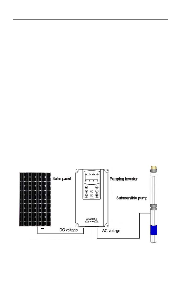
A complete solar Pump system consist of solar array, pump and solar Pump inverter. The
inverter can convert DC power from solar PV array to AC power to run pump motors.
Solar array, an aggregation of many solar modules connected in series and parallel,
absorbs sunlight radiation and converts it into electrical energy, providing dynamical water
for the whole system.
Inverter controls the system operation and adjust the output frequency in real-time
according to the variation of sunlight intensity to realize the maximum power point tracking
(MPPT).
Pump, drive by 3-phase or single phase AC motor, can draw water from the deep wells or
rivers and lakes to pour into the storage tank or reservoir, or directly connect to the
irrigation system, fountain system, etc.
Figure 1 Structure of solar Pump system

Solar Pump Inverter Chapter 2 Solar Pump Inverter
7
Chapter 2 Solar Pump Inverter
2.1 Model Description
Model numbers on name plate consist of numbers, symbols, and letters, to express its
respective series, suitable power type, power level and other information.

Solar Pump Inverter Chapter 2 Solar Pump Inverter
8
2.2 Name plate
2.3 Parameters
2.3.1 CT112 series parameters
CT112 Solar Pump Inverter
Model
Rated
Power
(KW)
DC Input
VOC
Voltage(V)
Recommend
VOC Voltage
(V)
Recommend
MPPT
Voltage (V)
Max. DC
Input
Current (A)
Rated
Output
Current(A)
Rated
output
Voltage(V)
Output
Frequency
(Hz)
CT112-2S-0.7G
0.75 300~450 388~450 320~370 8.5 5.5 1PH 220 0-50/60
CT112-2S-1.5G
1.5 300~450 388~450 320~370 14 10 1PH 220 0-50/60
CT112-2S-2.2G
2.2 300~450 388~450 320~370 23 13.8 1PH 220 0-50/60
CT112-2S-4.0G
4 300~450 388~450 320~370 35 20 1 PH 220
0-50/60
CT112-2T-0.7G
0.75 200~450 388~450 320~370 8.5 4.5 3PH220 0-50/60
CT112-2T-1.5G
1.5 200~450 388~450 320~370 14 7.0 3PH220 0-50/60
CT112-2T-2.2G
2.2 200~450 388~450 320~370 23 10 3PH220 0-50/60
CT112-2T-4.0G
4 200~450 388~450 320~370 35 16 3PH220 0-50/60
CT112-2T-5.5G
5.5 200~450 388~450 320~370 50 20 3PH220 0-50/60

Solar Pump Inverter Chapter 2 Solar Pump Inverter
9
CT112-4T-0.7G
0.75 300~780 670~780 540~ 630 8.5 2.5 3PH380 0-50/60
CT112-4T-1.5G
1.5 300~780 670~780 540~630 8.5 3.7 3PH380 0-50/60
CT112-4T-2.2G
2.2 300~780 670~780 540~630 14 5.3 3PH380 0-50/60
CT112-4T-4.0G
4.0 300~780 670~780 540~630 23 9.5 3PH380 0-50/60
CT112-4T-5.5G
5.5 300~780 670~780 540~ 630 23 14.0 3PH380 0-50/60
CT112-4T-7.5G
7.5 300~780 670~780 540~630 35 18.5 3PH380 0-50/60
CT112-4T-11G
11 300~780 670~780 540~630 35 25.0 3PH380 0-50/60
CT112-4T-15G
15 300~780 670~780 540~630 50 32.0 3PH380 0-50/60
CT112-4T-18.5G
18.5 300~780 670~780 540~ 630 50 38.0 3PH380 0-50/60
CT112-4T-22G
22 300~780 670~780 540~630 75 45.0 3PH380 0-50/60
CT112-4T-30G
30 300~780 670~780 540~630 75 60.0 3PH380 0-50/60
CT112-4T-37G
37 300~780 670~780 540~630 100 75.0 3PH380 0-50/60
CT112-4T-45G
45 300~780 670~780 540~ 630 100 92.0 3PH380 0-50/60
CT112-4T-55G
55 300~780 670~780 540~630 150 115.0 3PH380 0-50/60
CT112-4T-75G
75 300~780 670~780 540~630 225 150.0 3PH380 0-50/60
CT112-4T-90G
90 300~780 670~780 540~630 300 180.0 3PH380 0-50/60
CT112-4T-110G
110 300~780 670~780 540~ 630 375 215.0 3PH380 0-50/60
CT112-4T-132G
132 300~780 670~780 540~630 450 260.0 3PH380 0-50/60
CT112-2S-0.4G
~4.0G
Input specification
Maximum Input PV Voltage
(PV Open-Circuit Voltage)
450VDC
Recommended MPPT
Voltage Range 320~370VDC(Vmp)
Recommended Input
Operation Voltage
388~450VDC (VOC)
Input specification
(Grid or backup
generator input) Input voltage 1PH 220V(-15%~30%)
Output
specification
Rated output voltage
1PH 220V
Output frequency 0~600.00Hz(default: 0~
60.00Hz)
Fault protection Built-in Protection
Protection of light load,
over-current, over-voltage,
output phase-lose, under-load,
under-voltage, short circuit,
overheating, water pump run
dry etc.
CT112-2T-0.7G
~5.5G
Input specification
(PV Input)
Maximum Input PV Voltage
(PV Open-circuit Voltage) 450VDC
Recommended MPPT
Voltage Range 320~370VDC(Vmp)
Recommended Input
Operation Voltage 388~450VDC (VOC)
Input specification
(Grid or backup
generator input) Input voltage 1PH 220V(-15%~30%)

Solar Pump Inverter Chapter 2 Solar Pump Inverter
10
Output
specification
Rated output voltage 3PH 220V
Output frequency 0~600.00Hz(default: 0~
60.00Hz
)
Fault protection Built-in Protection
Protection of light load,
over-current, over-voltage,
output phase-lose, under-load,
under-voltage, short circuit,
overheating, water pump run
dry etc.
CT112-4T-0.7G
~132G
Input
specification(PV
Input)
Maximum Input DC
Voltage
(PV Open-circuit Voltage)
780VDC
Recommended MPPT
Voltage Range 540~630VDC(Vmp)
Recommended Input
Operation Voltage
670~780VDC (VOC)
Input
specification(Grid
or backup
generator input)
Input Voltage Range Three phase 380VAC(-15%~
30%)
Output
specification
Rated output voltage
3PH 380VAC
Output frequency 0~600.00Hz(Default 0~
60.00Hz)
Fault protection Built-in Protection
Protection of light load,
over-current, over-voltage,
output phase-lose, under-load,
under-voltage, short circuit,
overheating, water pump run
dry etc.
Keypad display LED display Highlight LED digital tube displays the inverter information
LCD display LCD displays inverter information
Others
Application Site No direct sunshine, no dust, corrosive gas, comb
ustible gas,
oil mist, steam, dripping or salinity etc.
Altitude 0~
2000m, Derated use above 1000m,per100m, the rated
output current decrease 1%.
Environment
Temperature
-10℃~50℃ (Environment Temperature be 40℃~50℃,
please keep derated use.)
Humidity 5~95%,non-condensation
Vibration
less than 5.9 m/s
2(
0.6g
)
Storage
Temperature -20℃~+70℃
Efficiency
Rated Power Run≥93%
Installation Wall or rail mounting
Cooling
Forced Air Cooling

Solar Pump Inverter Chapter 2 Solar Pump Inverter
11
2.3.2 CT112A series parameters
CT112A Solar Pump Inverter
CT112A-2S/2T-XXX 0.7 1.5 2.2
Rated output power(kW)0.7 1.5 2.2
Max. DC input current(A)9 12 12
Rated AC input current—AC type(A)9.3 15.7 24
Rated output current(A)4.5 10 14
Note: Output current is defined as rated value at single 220V output voltage, and output
current at three phase output is counted additionally according to the power.
Mode CT112A-2S-0.7
CT112A-2T-0.7
CT112A-2S-1.5
CT112A-2T-1.5
CT112A-2S-2.2
CT112A-2T-2.2
DC INPUT
Max. DC voltage(V) 450
Starting voltage(V)
80
100
Min. Operation voltage(V) 60 80
Recommended MPPT
voltage(V)
80~400 100~400
Input channel One channel:MC4
Max. DC input current(A)
9
12
Bypass AC input (model supports mains input)
Input voltage(Vac)
220/230/240(1PH)
(
-15%~+10%
)
Input frequency(Hz)47~63
AC input terminal
1P2L
AC output
Rated
(
W
)
750
1500
2200
Rated current(A)5.1(1PH)
4.2(3PH)10.2(1PH)
7.5(3PH)14(1PH)
10(3PH)
Output voltage(Vac)
0~input voltage
Output wiring mode
1P2L/2P3L/3P3L
Output frequency
(
Hz
)
1~400
Control performance
Control mode
MPPT
Motor type
Asynchronous motor
Other parameters
Dimension
(
L*W*H
)(
mm)
314*280*128
Protection level
IP54
Cooling mode
Natural cooling
HMI
External LED keypad
Communication terminal
External communication
RS485/3 digital inputs
Operation environment
Ambient temperature
-25
℃~60℃(
derate when the temperature is above 45
℃)
Operation altitude
3000 m
(
derate when the altitude is above 2000m
)
Warranty
18 months

Solar Pump Inverter Chapter 2 Solar Pump Inverter
12
2.4 External Dimensions
2.4.1 CT112 series solar pump inverter
Figure 2 Dimensions (CT112:11KW and below)
Figure 3 Dimensions(CT112:15KW~132KW)

Solar Pump Inverter Chapter 2 Solar Pump Inverter
13
Table 1 Dimensions of CT112 series inverter
Power(kw
)
Size(mm)
Installation
Hole(mm)
Weight
(kg)
Shape of
Inverter
W
H
D
W1
H1
H2
CT112-2S-0.4G 126
186
155
115
175
---
5
1.6
C0
CT112-2S-0.7G
CT112-2S-1.5G
CT112-2S-2.2G
CT112-2S-4.0G
140 230 172 128 218 --- 5.5 3.5 C1
CT112-2T-0.7G 126 186 155 115 175 --- 5 1.6 C0CT112-2T-1.5G
CT112-2T-2.2G
CT112-2T-4.0G 140 230 172 128 218 --- 5.5 3.5 C1
CT112-2T-5.5G 165 285 200 153 273 --- 5.5 5.5 C2
CT112-4T-0.7G
126 186 155 115 175 --- 5 1.6 C0
CT112-4T-1.5G
CT112-4T-2.2G
CT112-4T-4.0G 140 230 172 128 218 --- 5.5 3.5 C1
CT112-4T-5.5G
CT112-4T-7.5G 165 285 200 153 273 --- 5.5 5.2 C2
CT112-4T-11G
CT112-4T-15G
214 402 205 184 360 385 7 11.5 C3
CT112-4T-18.5G
CT112-4T-22G
CT112-4T-30G 250 442 230 220 405 425 7 19 C4
CT112-4T-37G
CT112-4T-45G 299 602 276 240 540 580 9 30 C5
CT112-4T-55G
CT112-4T-75G
329 660 332 250 601 640 9 56 C6
CT112-4T-90G
CT112-4T-110G
CT112-4T-132G

Solar Pump Inverter Chapter 2 Solar Pump Inverter
14
2.4.2 CT112A solar pump inverter
Figure 4 CT112A series dimension diagram
Table 2 Dimensions of CT112A series inverter
Mode Height H1
(mm)
Width W1
(mm)
Depth D
(mm)
Height H2
(mm)
Width W2
(mm)
Installation
hole
CT112A-2S/2T-0.7
280 314 128.2 264 256 M6
CT112A-2S/2T-1.5
CT112A-2S/2T-2.2

Solar Pump Inverter Chapter 3 System Collection Diagram
15
Chapter 3 System Collection Diagram
3.1 CT112 Series Main Circuit Terminals
3.1.1 Schematic Diagram for Connection of Main Circuit Terminals
①Connection diagram of main circuit for the inverter of 220v
②Connection diagram of main circuit for the inverter of 380v 0.7~ 22KW
③Connection diagram of main circuit for the inverter of 380v 30~ 37KW
④Connection diagram of main circuit for the inverter of 380v 45~55kw
⑤Connection diagram of main circuit for the inverter of 380v 75~ 132kw

Solar Pump Inverter Chapter 3 System Collection Diagram
16
3.1.2 Instructions of Main Circuit Terminals of Inverter:
Terminal Description
R、S、T Terminals of 3 phase AC input
(+)、(-) Terminals of 2 phase DC input
(+)、PB Spare terminals of external braking resistor
P1、(+) Spare terminals of external DC reactor
(-) Terminal of negative DC bus
U、V、W Terminals of 3 phase AC output
Terminal of ground
● the voltage class of CT112 series inverter 3phase power has 2 class: 220V, 380V,
before connecting power, please make sure the power class on inverter nameplate is
the same with the accessing power. Otherwise do not connect.
● DC bus (+) (-)terminal: take note that when power outrage there is residual voltage on
DC bus P+ P- terminal, need to wait for a while until CHARGE LED off. Otherwise it is
danger of electric shock.
●When selecting external brake unit, note the polarity of P= (+) and (-) cannot be
reversely connected, otherwise it can result in damage or even fire.
Do not directly connect brake resistor to DC bus, it may result damage or fire.
1)Input power L,N or R, S T: the cable connection at input side of the inverter has no
phase sequence requirement.
2)Brake unit cable length should not exceed 10m, twisted pair or double cable parallel
wiring should be used.
3)Brake resistor connecting terminal (+) (-): confirm whether the device has built-in
brake unit, its brake resistor connecting terminal is effect. The brake resistor selection
table 2-4 recommending value and the wiring distance should less than 5M.
Other it can damage inverter.
This manual suits for next models
24
Table of contents
Other dolycon Inverter manuals
Popular Inverter manuals by other brands

HGI Generators
HGI Generators HRD060D Operation and maintenance manual

Controlled power company
Controlled power company UltraLITE Series owner's manual

ToolPRO
ToolPRO PLU 553024 instruction manual

GTI
GTI YSmart user manual

Portawattz
Portawattz 600 Oweners manual

Fujitsu
Fujitsu Frenic Eco FRN-F1 Starting guide