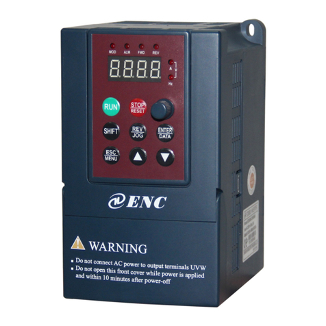
ENC EN600PV Series User manual

PV Pump Inverter User Manual
EN600PV Series
Ver. 1.0
ISO9001:2015 Quality Management System Authentication
SHENZHEN ENCOM ELECTRIC TECHNOLOGIES CO., LTD

Print version:V1.0-A0
Foreword
Thank you for purchasing EN600PV series photovoltaic water pump inverter developed and
produced by Shenzhen Encom Electric Technologies CO., LTD.
EN600PV series photovoltaic water pump inverter is a special inverter specially designed
for photovoltaic water pump based on the application requirements of photovoltaic water pump. It
is built-in maximum power tracking algorithm, can realize the efficient use of solar energy. It has
special protection functions, such as weak light sleep and wake up function, low frequency
protection, full water protection, dry pumping protection, etc. It’s standard configuration with
Modbus and supports CAN bus, Profibus-DP bus and other communication functions. At the same
time, EN600PV series built-in output default phase protection, short circuit to the ground
protection and other hardware protection functions, effectively improve the reliability and safety of
the system.
This brochure provides the installation and wiring, settings, fault check and methods,
maintenance and other relative issues to customer. To ensure the inverter assemble and operate
rightly, and use with its high performance, please read this brochure carefully before installation,
keep it well and pass it to the end users.
Please contact our office or dealer anywhere at any moment when you have any doubts or
special demands in using these inverters, and you can also contact our after-service center in our
Headquarters directly. Sincerely at your service!
You are without prior notice if we change contents of this manual.
ENC

1
Content
1 Safety information and use notice points .....................................................................................1
1.1 Safety precautions....................................................................................................................1
2 Inverter type and specification......................................................................................................3
2.1 Incoming inverter inspect ........................................................................................................3
2.2 Type explanation......................................................................................................................3
2.3 Nameplate explanation ............................................................................................................3
2.4 Inverter type explanation .........................................................................................................4
2.5 EN600 Appearance and parts name explanation.....................................................................4
2.6 Appearance and parts name explanation .................................................................................5
2.7 Outer size of keypad and its fixing box (unit:mm) .................................................................6
2.8 Product technic index and spec ...............................................................................................6
3 Installation and wiring ...................................................................................................................8
3.1 Main loop terminal wiring.......................................................................................................8
3.2 Basic running wiring diagram ...............................................................................................10
3.3 Control loop collocation and wiring......................................................................................10
3.3.1 Descriptions for control board terminal .......................................................................10
4 Run and operation explanation for inverter...........................................................................13
4.1 Run mode...............................................................................................................................13
4.2 Operation and use of key board.............................................................................................13
4.2.1 Keypad layout...............................................................................................................13
4.2.2 Keypad function description ........................................................................................14
4.2.3 LED and indicator light ................................................................................................15
4.2.4 Key board display status...............................................................................................15
4.2.5 User Management Parameters......................................................................................17
4.2.6 Method for operating keypad .......................................................................................17
5 Function parameter schedule graph........................................................................................20
5.1 Symbol description ................................................................................................................20
5.2 Function parameter schedule graph........................................................................................20
6 Debugging specification ............................................................................................................60
6.1 Detailed function description of Solar inverter .....................................................................60
6.1.1 System Parameter Group:F00 ......................................................................................60
6.1.2 On-off input function parameter group: F08................................................................61
6.1.3 Photovoltaic special function parameter group:F12 ....................................................62
6.2 Ooperation instructions for asynchronous motor pumps ......................................................65
6.3 Introduction of protection function of photovoltaic inverter ................................................66
7 Troubleshooting .........................................................................................................................67
7.1 Failure and countermeasure...................................................................................................67
7.2 Failure record lookup.............................................................................................................71
7.3 Failure reset............................................................................................................................72
7.4 Alarm reset.............................................................................................................................72
8 Maintenance ...............................................................................................................................73
8.1 Routine maintenance .............................................................................................................73
8.2 Inspection and replacement of damageable parts..................................................................73
8.3 Repair guarantee ....................................................................................................................73
8.4 Storage ...................................................................................................................................74
Appendix A Modbus Communication Protocol ........................................................................75
Appendix B Accessories Selection...............................................................................................87
ENC

Safety information and use notice points
1
1 Safety information and use notice points
To make ensure personal & equipment safety, this chapter must be read carefully before the
inverter come into use.
1.1 Safety precautions
There are three kinds of safety warnings in this manual as below:
Symbol Symbol description
It may cause human death, serious injury or heavy property loss with wrong operation
It may result body or device damage with wrong and timeless
precautions under operation.
Should pay extra cautions when inverter in use under this
symbol.
!
!
Note
!
Forbid to cut off the power source directly when inverter under running, acceleration or
deceleration status. Power source could cut off when inverter completely in halt and
standby status. Otherwise user should be responsible for inverter and device damage and
human injury.
!
(1) Forbid to connect AC power source to output terminal U, V, W, otherwise it could
cause inverter completely damage.
(2) Not allow for short circuit between(-)and(+),Otherwise it could cause inverter
damage and power source short circuit.
(3) Forbid to install inverter on flammable objects, otherwise it may cause fire.
(4) Do not install inverter in a environment with explosive gas, it may cause
explosion.
(5) Bare connection terminal should be insulation treatment after main loop
connection, otherwise it may cause electric shock.
(6) Do not operate inverter with wet hands when inverter power on, otherwise it may
cause electric shock.
(7) Inverter earth terminal should be well grounding connection.
(8) Do not open the front cover for wiring when inverter power on. Inverter wiring
and check must handle after 10 minutes of inverter power off.
(9) Wiring connection should handle by qualified person and not allow to slip any
conductive objects inside inverter, otherwise it may cause a electric shock or inverter
damage.
(10) When inverter stocked for more than 6 months, using voltage regulator to boost
voltage up and keep inverter in standy status for 1 hour, otherwise it may cause
electric shock and ex
p
losion.
ENC

Safety information and use notice points
2
(1) Forbid to connect control terminals except TA, TB, TC to AC 220V/380V signal,
otherwise it may cause inverter completely damage.
(2) Do not install and run inverter when inverter damage or spare part less, otherwise it
may cause fire or human injury.
(3) Inverter should install in a place where can accept itself weight, otherwise it may
cause inverter drop down or belongings damage.
!
ENC

Inverter type and specification
3
2 Inverter type and specification
2.1 Incoming inverter inspect
(1) Check if there is damage during transportation and inverter itself has damage or fall-off
parts.
(2) Check if parts presented in packing list are all ready.
(3) Please confirm nameplate data of the inverter is in line with your order requirement.
Our product is guaranteed by strict quality system during manufacturing, packing,
transportation etc., please contact our company or local agent rapidly if some careless omission or
mistake arise, we’ll deal with it as soon as possible.
2.2 Type explanation
EN600PV – 4T 0015
Fig.2-1 Type description
2.3 Nameplate explanation
Nameplate presented as Fig.2-2 with type and rating data at the bottom of inverter right side.
Fig.2-2 Nameplate
Code Name
EN600PV Series No.
Code Vo l t . g r a d e
2S 1 phase220V
4T 3 phase 380V
Code motor power
(KW)
0004 0.4
0007 0.75
… …
0220 22
0370 37
Series No.
Serial No.
Rated input vol. and freq.
Motor power and output current
Type
Manufacturer and origin
EN600PV INVERTER
TYPE: EN600PV-4T0370
SOURCE: 3PH 380V 50/60Hz
OUTPUT: 37KW 75A
S.N.:
ENC

Inverter type and specification
4
2.4 Inverter type explanation
Input
Voltage Inverter type
Rated
output
Current(A)
Adaptable
motor
(KW)
Recommended
Battery Board
Input Power (KW)
Maximum
DC Input
Voltage (V)
Recommended
battery panels
Voltage (V)
1 phase
220V
EN600PV-2S0004 2.5 0.4 0.55 410 330~400
EN600PV-2S0007 4 0.75 1.0 410 330~400
EN600PV-2S0015 7 1.5 1.95 410 330~400
EN600PV-2S0022 10 2.2 2.86 410 330~400
EN600PV-2S0037 15 3.7 4.8 410 330~400
3 phase
380V
EN600PV-4T0007 2.3 0.75 1.0 780 600~750
EN600PV-4T0015 3.7 1.5 1.95 780 600~750
EN600PV-4T0022 5 2.2 2.86 780 600~750
EN600PV-4T0037 8.5 3.7 4.8 780 600~750
EN600PV-4T0055 13 5.5 7.2 780 600~750
EN600PV-4T0075 17 7.5 9.75 780 600~750
EN600PV-4T0110 25 11 14.3 780 600~750
EN600PV-4T0150 33 15 19.5 780 600~750
EN600PV-4T0185 39 18.5 24 780 600~750
EN600PV-4T0220 45 22 28.6 780 600~750
EN600PV-4T0300 60 30 39 780 600~750
EN600PV-4T0370 75 37 48 780 600~750
2.5 EN600 Appearance and parts name explanation
Fig.2-3 Parts name sketch of inverter
LED Digital tube
Operation keyboard
Nameplate
Input&output
power cable inlet
LED Digital tube
Operation keyboard
Nameplate
Up cover plate
Input&output
power cable inlet
Down cover plate
Control cable inlet
Fan hole
Fan hole
Control cable inlet
Down cover plate
Up cover plate
ENC

Inverter type and specification
5
2.6 Appearance and parts name explanation
Fig.a Fig.b
Fig.2-4 Appearance
Table 2-1 Mounting size
Inverter model W
(mm)
H
(mm)
D
(mm)
D2
(mm)
A
(mm)
A1
(mm)
B
(mm)
W1
(mm)
D1
(mm)
Fix Hole
(mm) Fig.No
EN600PV-2S0004
115 200 151 164 104 - 186 - - 5 Fig.a
EN600PV-2S0007
EN600PV-2S0015
EN600PV-2S0022
EN600PV-2S0037
EN600PV-4T0007
EN600PV-4T0015
EN600PV-4T0022
EN600PV-4T0037
EN600PV-4T0055 140 240 175 188 129 - 227 - - 5 Fig.a
EN600PV-4T0075
EN600PV-4T0110 180 304 189 202 165 - 281 - - 6 Fig.a
EN600PV-4T0150
EN600PV-4T0185 250 398 210 223 180 - 382 - - 9 Fig.b
EN600PV-4T0220
EN600PV-4T0300 280 450 240 253 180 - 434 - - 9 Fig.b
EN600PV-4T0370
H
W
A
B
D
D2
安装孔
B
H
A
WD
D2
安装孔
Mounting holes
Mounting holes
ENC

Inverter type and specification
6
2.7 Outer size of keypad and its fixing box (unit:mm)
Fig.2-5 Mounting size of keypad Fig.2-6 Hole size of keypad
2.8 Product technic index and spec
Item Item description
Input
(Ac)
Rating volt., frequency 1 phase 220 Volt class: 1 phase 220V, 50Hz/60Hz;
3 phase 380 Volt class: 3 phase 380V, 50Hz/60Hz.
Allowed volt. range 1 phase 220 Volt class: 200~260V;
3 phase 380 Volt class: 320~460V.
Input
(Ac)
Recommended MPPT
operating voltage
1 phase 220 Volt class: 330VDC
3 phase 380 Volt class: 550VDC
Recommended
operating voltage range
1 phase 220 Volt class: 300~400VDC
3 phase 380 Volt class: 600~750VDC
Output
Voltage 0~380V
Frequency 0~600Hz
Over loading capacity 150% of rated current for 1 minute
Running
function
running command
specified channel
Keypad specified, control terminal specified, communication
specified can switch through various means
Running frequency
specified channel
Main & auxiliary specified to a realize one main adjusting and one fine
control. Digital specified, analog specified, pulse specified,pulse width
specified, communication specified and others, which can
b
e switched
by many means at any time
Binding function Run command channel and frequency specified channel can bind
together randomly and switch synchronously
Input output
characteristic Digital input channel
Channel 8 for universal digital input, max. Frequency 1KHz,channel 1
can be used as pulse input channel, max. Input 50KHz,which can be
expanded to channel 14 .
88
140
82.8
134.5
67
109.5
107.5
64.5
16
17.9
7.1
Note
(1) EN-LCD2 long-distance keypad outer lead, do not support keypad holder installed,
only keypad installed support, mounting size refer to Fig.2-5.
(2) Except EN-LCD2 long-distance keypad, when other keypad outer lead, user can
adjust the hole size under actual situation on keypad or keypad holder; thickness of install
board between 1.0~1.5mm is suggested.
(3) When installed with keypad holder, it need to buy extra.
ENC

Inverter type and specification
7
Analog input channel
Channel 2 for analog input channel, AI1 can choose 4~20mA or 0~
10V output,
AI2 is differential input channel,
4
~20mA or -10~10V
for option,which can be expanded to channel 4 analog input.
Pulse output channel 0.1 ~20KHz pulse square signal output to achieve setting frequency,
output frequency and other physical quantity output
Analog output channel
Channel 2 for analog signal output, AO1 can choose 4~20mAor 0~
10V, AO2 can choose 4~20mA or 0~10Vto achieve setting frequency,
output frequency and other physical quantity output,which can be
expanded to channel 4 analog output.。
keypad Keypad display The parameters as setting frequency, output frequency, output voltage,
output current can be displayed.
Button Locked Lock all or part of the buttons.
Protection function
Motor power on Shot circuit test, input & output phase loss protection,
over-current protection, over voltage protection, under voltage
protection, over heat protection, overload protection, under load
protection, relay absorption protection, terminal protection and no stop
protection under power off
Environment
Application site Indoor, not bare to sunlight, no dust, no corrosive gas, no flammable gas,
no vapor, no water drop or salt etc
Altitude
Under 1000 meter.(above 1000 meter require to reduce volume to use,
output current reduce about 10% of rated currenvolt per 1000 meter
high)
Environment
temperature
-10℃~+40 ( environment temperature between 40 ℃℃~
50℃,Need to reduce volume or strengthen heat sink )
Environment humidity Smaller than 95%RH,no drop condenses
Vibration Smaller than 5.9 M/S²(0.6g)
Storage temperature -40℃~+70℃
Structure Protection grade IP20
Cooling mode Forced air cooling
Installation Wall hanging
Note
To get a perfect usage performance of the inverter, Please check and select right type
according to this chapter before wiring.
!It is necessary to select right type, otherwise it may cause motor abnormal run or inverter
damage.
ENC

Installation and wiring
8
3Installation and wiring
3.1 Main loop terminal wiring
(1) Main loop input output terminal show as Table 3-1, 3-2.
Table 3-1 EN600 PV main loop input output terminal description
Adapted type Main loop terminal Termi nal
name Function description
EN600PV-2S0004
~
EN600PV-2S0022
L1、L2 1 phase AC input terminal,
connect power source
(+)DC volt. Positive terminal
PB External connect to brake
resistor reverse terminal
(-)DC volt. Negative terminal
U
、V、W3 phase AC output terminal,
connect to motor
Grounding terminal
EN600PV-2S0037
L1、L2 1 phase AC input terminal,
connect power source
(+)DC volt. Positive terminal
PB External connect to brake
resistor reverse terminal
(-)DC volt. Negative terminal
U
、V、W3 phase AC output terminal,
connect to motor
Grounding terminal
EN600PV-4T0007
~
EN600PV-4T0150
R
、S、T 3 phase AC input terminal,
connect power source
(+)DC volt. Positive terminal
PB External connect to brake
resistor reverse terminal
(-)DC volt. Negative terminal
U
、V、W3 phase AC output terminal,
connect to motor
Grounding terminal
EN600PV-4T0185
EN600PV-4T0220
R
、S、T 3 phase AC input terminal,
connect power source
(+)External connect to DC reactor
PB External connect to brake
resistor reverse terminal
(-)DC volt. Negative terminal
(+)、(-)External connect brake unit
U、V、W 3 phase AC output terminal,
connect to motor
Grounding terminal
RS T U
(-)
PB VW
(+)
RS T U
(-)
PB VW
(+)
ENC

Installation and wiring
9
EN600PV-4T0300
EN600PV-4T0370
R
、S、T 3 phase AC input terminal,
connect power source
PB External connect to DC reactor
(+)External connect to brake
resistor reverse terminal
(-)DC volt. Positive terminal
(+)、(-)DC volt. Negative terminal
U、V、W 3 phase AC output terminal,
connect to motor
Grounding terminal
RS T U
(-)
PB VW
(+)
!The wiring of main loop must connect right according to the description above. Wrong
wiring will cause device damage and personal injury
ENC

Installation and wiring
10
3.2 Basic running wiring diagram
Fig. 3-1 Basic wiring diagram
3.3 Control loop collocation and wiring
3.3.1 Descriptions for control board terminal
(1) CN3 and CN4 terminal layout as following description 3-3
Table 3-3 Function table for control board terminal
Type Symbol Description Terminal Function and specification
Multifunction
input terminal
X1 Multifunction input 1 Input voltage range: 15~30V;
Opto coupler isolation, Compatible with bipolar
input;
Input impedance: 4.7KΩ
X2 Multifunction input 2
X3 Multifunction input 3
X4 Multifunction input 4
1
2
3
4
5
6
X1
X2
X3
X4
X5
X6
X8/DI
COM
+10V
0~10V AI1
4~20mA
-10V~+10V AI2
GND
Short
circuit slice
M
DO:frequen
cy meter
24V pulse
Internal optocoupler isolation input
A02
Analog output type
AO1 switch SW3
GND
TC
TB-TC close
TA-TC open
TB
485+
485-
485 communication
port
Twisted-pair cable
Analog input type SW1 switch(AI1 valid)
Brake unit(external connect fitting part)
U
V
W
Y3
Y4/DO
Multi-function
R
S
T
Ampere meter
4~20mA
Voltmeter
0~10V
V:0~10V
A:4~20mA
Open
Close
Com-mon
TA
Relay load
X7
7
8
PW
+24V
X terminal active,electric level
support high level and low level
COM
Y1
Y2
24V
+
A01
AO2 switch SW4
V
A
■
A
■
V
Must set parameter F00.20 when SW2 switch
(+) PB (-)
Brake resistance(external connect fitting part)
L1 220VAC
L2 220VAC EN600PV
Lower level valid---short circuit
slice connect PW and +24V,
external wiring show as solid line
High level valid---short circuit slice
connect PW and COM,
external wiring show as dotted line
Used as hi-speed pulse input
terminal DI)
When external power source
used,remove the short circuit slice
Analog input type SW2 switch(AI2 valid)
V:-10V~+10V voltage input
A:4~20mA current input
AI2 {
V:0~10V voltage input
A:4~20mA current input
AI1 {
AC380V
50/0Hz
ENC

Installation and wiring
11
X5 Multifunction input 5 max input frequency: 1KHz
X6 Multifunction input 6
X7 Multifunction input 7
X8/DI Multifunction input
8/high-speed pulse input
Except for X1~X7 function, It can be used as
hi-speed pulse input.
Input impedance: 2.2KΩ
max input frequency: 50KHz
Power source
+24V +24V power source Provide +24V power to external device
(24±4V)
Max output current: 200mA
PW External power source
input
factory default connect to +24V;when use
external signal to drive X terminal, It need to
connect to external power source and cut off with
+24V power terminal.
+10V +10V power source Provide +10Vpower to external device (10±0.5V)
Max output current:50mA
COM Common interface Reference ground for digital signal and +24V
power
GND Common interface Reference ground for analog signal and +10V
power
Analog input
AI1 Analog output 1
Input range:DC 0V~10V/4~20Ma, selected
by
SW1 dial switch on control board.
Input impedance :voltage input at 20KΩ;
current input at 250Ω.
resolution: 1/4000
AI2 Analog output 2
Input range: DC-10V~10V/4~20mA,
selected
by the second figure of F00.20 and SW2 dial
switch on control board.
Input impedance: voltage input at 20KΩ;
Current input at 250Ω. Resolution: 1/2000
Analog
output
AO1 Analog output 1
Voltage or current output is selected by SW3
(AO1) and SW4(AO2)dial switch on control
board.
Output voltage range: 0~10V
Output current range: 4~20mA
AO2 Analog output 2
Multifunction
output
terminal
Y1 Open circuit collector output 1 Opto coupler isolation output ,unipolar Open
circuit collector output
Max voltage output: 30V
Max current output: 50mA
Y2 Open circuit collector output 2
Y3 Open circuit collector output 3
Y4/DO
Open circuit collector
output 4/
High-speed impulse
output
Function code F00.22 to select terminal output
mode When Open circuit collector output, with
the same spec as terminal Y.
When High-speed impulse output ,the max
frequency is 20KHz.
RLY1
output
TB—TC Normal closedterminal Contact capacity:AC250V/2A(cosφ=1)
AC250V/1A(cosφ=0.4)
DC30V/1A
TA—TC Normal open terminal
Communi
cation
interface
485+ 485 differential
signal interface
485 differential signal positive terminal
485- 485 differential signal negative terminal
ENC

Installation and wiring
12
Auxiliary
interface
CN2 retain
CN6 StandardRS485
communication interface Twisted-pair cable or shield wire to connect
(2)RS485 crystal outlet CN6 layout as following
1
2
3
45
6
78
RS485 terminal CN6 layout
No. 1 2 3 4 5 6 7 8
Name 485+ 485- - - - - - -
ENC

Run and operation explanation for inverter
13
4 Run and operation explanation for inverter
4.1 Run mode
EN600PV inverter have 3 kinds of run mode, following is in turn according to their priority,
jog run →solar mode→common run. Shown as Fig.4-1.
Fig.4-1 Run mode
0: Jog run
Upon receiving jog run command (for instance, press the key on keypad) during waiting
state, the inverter run at jog frequency (see function code F01.25~F01.29).
1: Photovoltaic operation
Set the PV operation control effective parameter F12.00>0, and the PV terminal prohibition
function of input terminal No. 72 is invalid, the inverter will enter the PV operation mode.
2: Common run
Common open loop run mode of general inverter.In above 6 kinds of run mode except “jog
run” the inverter can run according to kinds of frequency setting method.
4.2 Operation and use of key board
4.2.1 Keypad layout
The operating keyboard is the main unit of frequency inverter to accept commands,display
parameters. Keyboard outline diagram shown in Fig.4-2.
Common run?
Jog run
Solar run
Common run
Electrification
Waiting
state
Any jog command?
Run command effective?
Solar effective?
Y
Y
Y
Y
N
N
N
N
High priorit
y
Low priority
ENC

Run and operation explanation for inverter
14
Fig.4-2 Keypad layout sketch
4.2.2 Keypad function description
There are 9 key-presses on inverter keypad, And function definition of each key is as shown
in Table 4-1.
Table 4-1 keypad function table
Key Name Function description
Program/Exit key Enter into or exit programming state
Shift/Supervision
key
Can choose modification digit of set data under editor state;
can switch display status supervision parameter under other state
Function/Data key Enter into or exit programming state
Rev/Jog key Under keypad mode: to press this key can set reverse run or Jog run
according to the 1st bit of parameter F00.15
Run key Enter into forward run under keypad mode
Stop/reset key
In common run status the inverter will be stopped according to set mode after
pressing this key if run command channel is set as keypad stop effective mode.
The inverter will be reset and resume normal stop status after pressing this key
when the inverter is in malfunction status.
Digital
potentiometer
It is the same as the function of increase and decrease key,rotate to the left
means decrease,rotate to the right means increase.
Increasing button To increase data or function code (to press it continuously can improve
increasing speed)
模式指示灯
变频器故障报警指示灯
显示电流指示单位(A) 显示频率指示单位(Hz)
显示电压指示单位(V)
变频器正转指示灯
变频器反转指示灯
编程/退出键
移位/监控键
反转/点动键
递增键
数字电位器
确认/数据键
递减键
停止/复位键
正转运行键
Current indicator ligh
t
Failure alarm indicator light
Mode indicator light
Voltage indicator light
Frequency indicator light
Forward run indicator ligh
t
Reverse run indicator ligh
t
Digital potentiometer
Confirm/Data key
Decrease key
Stop/Reset key
Forward run key
Increase key
Exit/Program key
Shift/Supervision key
Reverse/Jog key
ENC

Run and operation explanation for inverter
15
Decreasing button To decrease data or function code (to press it continuously can improve
decreasing speed)
4.2.3 LED and indicator light
4 status indicator light: they are MOD(mode):ALM (alarm):FWD(forward run):REV(Reverse
run)from left to right on the LED: their respective indicating meaning is as shown in Table 4-2.
Table 4-2 Status indicator light description
Item Function description
Display function
Digital display Display current run status parameter and set parameter
Status indicator light
A, Hz, V Unit for relevant current digital displayed physical parameter(for
current is A:for voltage is V:for frequency is Hz)
MOD This indicator light is lit in non-supervision status and extinguished
if no key pressed for a minute: then come back to supervision status
ALM Alarm indicator light: indicate that the inverter is in over current or over voltage
suppressing status or failure alarm status currently
FWD
Forward run indicator light, indicate that the
inverter output forward phase order and the
connected motor rotate in forward direction The inverter work in DC brake
status if FWD,REV indicator
light is lit at the same time
REV
Reverse run indicator light: indicate that the
inverter output reverse phase order and the
connected motor rotate in reverse direction
4.2.4 Key board display status
EN600PV keypad display status is classified as Waiting status parameter display;Function
code parameter editing status display; Malfunction alarm status display; Run status parameter
display; Alarm state display in total 5 kinds of status. LED indicator light will all be lit after the
inverter electrified. Then enter into set frequency display. As shown in Fig.4-3 a.
(1) Waiting parameter display status
The inverter is in waiting status and waiting status supervision parameter is displayed on keyboard:
normally parameter F00.13 decide which status supervision parameter to be displayed. As shown in
Fig.4-3 b,the indicator light shows the unit of the parameter.
To press key, it can display different waiting status supervision parameter circularly: for
detail please see C-00 to C-05 group supervision parameter details decide by F00.07~F00.12.
(2) Run parameter display status
The inverter enters into run status when receiving effective run command and normally parameter
F00.13 decide which status supervision parameter to be displayed on the keypad. As shown in Fig.4-3
c,the indicator light shows the unit of the parameter.
To press key can display run status supervision parameter circularly. For detail please see
C-00 To C-05 group supervision parameter details decide by F00.01~F00.06 .
ENC

Run and operation explanation for inverter
16
Fig.4-3 Inverter electrification: waiting: run status display
(3) Failure alarm display status
The inverter enters into failure alarm display status upon
detecting failure signal and display failure code sparklingly(as
shown in Fig.4-4); To press key can look over relative
parameter after stopping running;Can press key to enter
into program status to see about F26 group parameter if want to
search failure information.
Can carry on failure restoration by key:control
terminal or communication command on the keypad after
troubleshooting. Keep displaying failure code if failure exist
continuously.
(4) Function code editing status
Under waiting, run or failure alarm status, press key, can enter into editing status(If
user password is set, can enter into editing status after inputting the password, see also F27.00
description),
and editing status is displayed according to three classes menu mode, as shown in Fig.
4-5. To press key can enter into one class by one class. Under function parameter display
status, to press key to carry on parameter storage operation; To press key can only
come back to upper class menu without storing modified parameter.
Fig.a Electrification,
display 8.8.8.8.8.
Fig.b waiting status, display
waiting status parameter
Fig.c run status: display run
status parameter
Set frequency Output frequency
Fig.4-4
over current in accelerating
!
For some serious failure, such as The earthing short circuit, Inverter modules protect, over
current, over voltage etc., must not carry on failure reset forcibly to make the inverter run
again without failure elimination confirmed. Otherwise have danger of damaging the
inverter!
ENC

Run and operation explanation for inverter
17
Fig.4-5 Keypad display status switching
(5) Alarm state display
When under running and standby situation:It means
enter failure alarm display status upon detecting failure
signal and display failure code sparklingly (Fig.4-6)
Inverter keeping running state But this alarm display can
not be reset button eliminated: After only find the cause
of the alarm: in order to eliminate this factor Normal.
4.2.5 User Management Parameters
In order to facilitate the user parameter management: EN600PVcomponent model parameter
menu for display management. The parameters do not need to be displayed can be shielded.
Method parameter setting mode display.
By setting F00.00=0,1,2,3 respectively parameter mode is set: Basic menu mode: menu mode
Intermediate: Advanced menu mode and user menu mode.
Basic menu F00,F01,F02,F03,F26
Middle menu F00,F01,F02,F03,F04,F05,F06,F07,F08,F09,F10,F11,F12,F13,F14,
F15,F16,F18,F19,F26
Advance menu F00,F01,F02,F03,F04,F05,F06,F07,F08,F09,F10,F11,F12,F13,F14,
F15,F16,F17,F18,F19,F20,F21,F22,F23,F24,F25,F26,F27
User custom F00.00 and F25 parameters group
4.2.6 Method for operating keypad
Can carry on various operation to the inverter through keypad, For example:
(1) Status parameter display switching:
After pressing key , Display C group status supervision parameter; after displaying one
supervision parameter code for 1 second will display this parameter value automatically. Press key
will go back to supervision interface.
electrificati
ENTER/DATA
ESC/MENU Second-class menu
First class menu
ESC/MENU
Waiting status parameter Display
or run status parameter display
or failure alarm displa
y
Output freq.switch display
ESC/MENU
Para. group Display control
Fig.4-6
Same main/assist frequency channel
ENC
This manual suits for next models
17
Table of contents
Other ENC Inverter manuals
Popular Inverter manuals by other brands
SMA
SMA SUNNY BOY 3000TL Single Tracker installation manual

Western Co
Western Co Leonardo Off-Grid 1kW-1500-24 MG user manual

OmniFlow
OmniFlow OMNILED 07 owner's manual

Italtecnica
Italtecnica Sirio Entry 230 owner's manual
Adlee Powertronic
Adlee Powertronic Adleepower AS1 instruction manual
MPP Solar
MPP Solar PIP 6048MGX-T user manual
