EFX C556 User manual

C556 Self Powered Elliptical Fitness Crosstrainerl
Page 1
C556 Self Powered Elliptical Fitness Crosstrainer
Warning: This service manual is for use by Precor trained service providers only.
IfyouarenotaPrecorTrainedServicer,youmustnotattempttoserviceanyPrecorProduct;
Call your dealer for service.
This document contains information required to perform the majority of troubleshooting, and
replacement procedures required to repair and maintain this product.
This document contains general product information, software diagnostic procedures (when
available), preventative maintenance procedures, inspection and adjustment procedures,
troubleshooting procedures, replacement procedures and electrical block and wiring diagrams.
To move directly to a procedure, click the appropriate procedure in the bookmark section to the
left of this page. You may “drag” the separator bar between this page and the bookmark section
to change the size of the page being viewed.
© 2003 Precor Incorporated
Unauthorized Reproduction and Distribution Prohibited By Law

C556 Self Powered Elliptical Fitness Crosstrainer
Page 2
Section One - Things You Should Know
Right, Left, Front, and Back Conventions
In this manual, right, left, front, and back are from the perspective of a user standing on the C556,
facing the display enclosure.
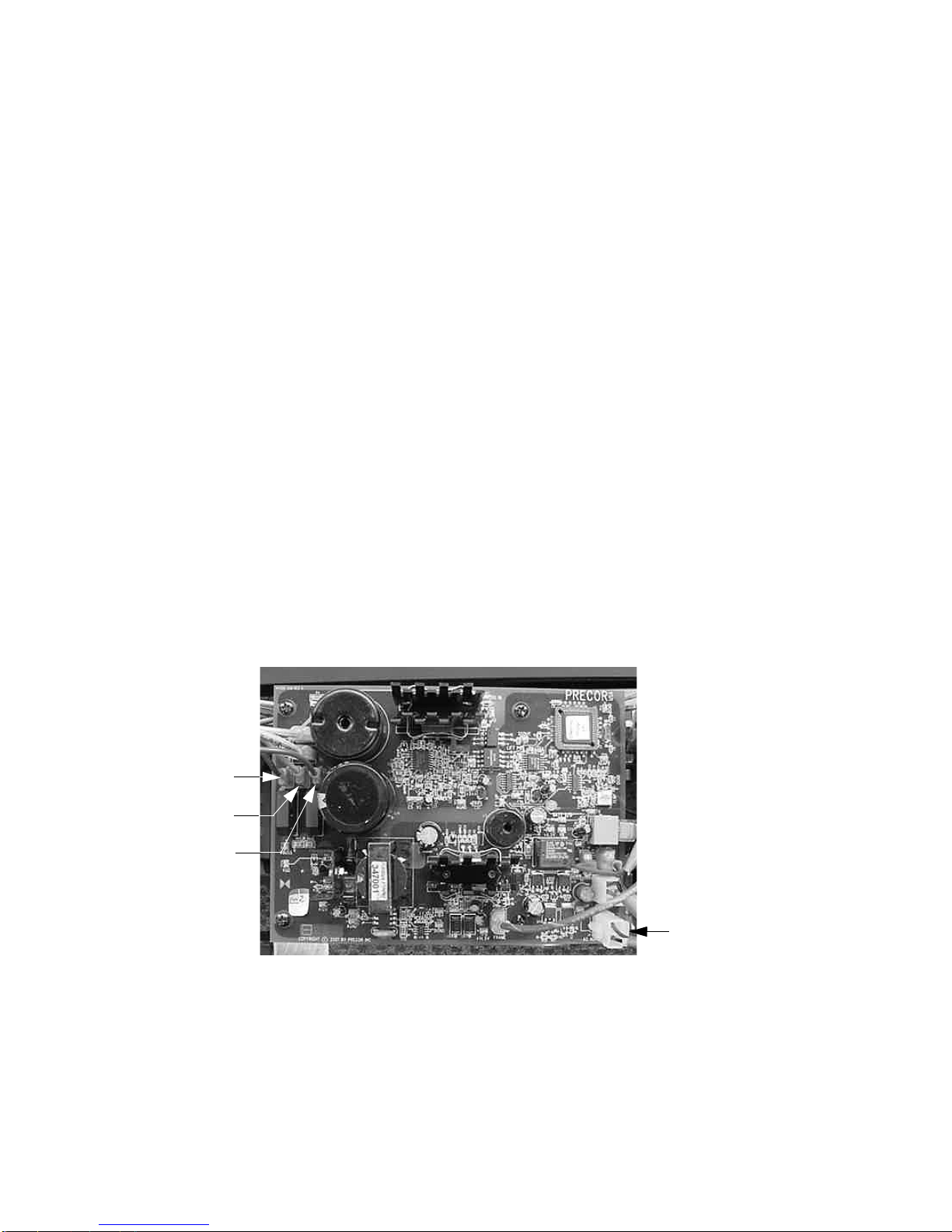
General System Information
• The generator performs three functions in the EFX. First, by controlling the amount of
electrical load applied to the generator, the user’s pedalling resistance is controlled.
Second, the generator is used to charge the EFX’s internal battery. Lastly, one of the
generators three phase output windings is monitored to determine when the unit is in use
and when it is idle. This system also determines the stride rate by determining the operating
speed (output frequency) of the monitored generator winding.
Warning and Caution Statements and General Safety Guidelines
Warning statements indicate a particularly dangerous activity. Warning statements you will find in
this manual include:
• If the EFX has been in recent use, the load resistors and load resistor mounting bracket may
be extremely hot.
• Because this is a self powered unit, it will either be necessary to either equip the unit with
the optional external power supply or have an assistant pedal on the unit while voltage
measurements are being taken. Because of the danger of working on the unit while it is in
motion using the optional external power supply is strongly recommended.
• When the unit is used, stairarms are in motion, the generator will operate and produce
potentially hazardous voltages even when the battery is disconnected.
• To remove power from the EFX, the optional external power supply (when equipped) must
be disconnected from the wall outlet and the red (positive) lead must be disconnected from
the battery. Always ensure that the EFX external power supply is unplugged from the wall
outlet and the red (positive) lead is removed from the battery when you inspect or adjust the
EFX, or when you isolate, remove, or replace an EFX component.
• Removing the covers exposes high voltage components and potentially dangerous
machinery. Exercise extreme caution when you perform maintenance procedures with the
cover(s) removed.
• During service operations you will be very close to moving machinery and voltage bearing
components. When you perform maintenance procedures with the covers removed, remove
jewelry (especially from ears and neck), tie up long hair, remove neck ties, and do not wear
loose clothing.

C556 Self Powered Elliptical Fitness Crosstrainerl
Page 3
• Exercise caution when touching any wire or electrical component during EFX operation.
• A pinching hazard exists when the unit is operated by turning the crankarms by hand. It is
possible to seriously pinch a finger between the crankarm and stairarm. The stairarms
should be removed before operating the crankarms by hand.Caution statements are
intended to prevent damage to the EFX as a result of the current activity. Caution
statements included in this manual are listed below:
• When it is necessary to lift or move the EFX, ensure that the EFX has adequate support and
that you use proper lifting techniques.
Safety guidelines you should know and follow include:
• Read the owner’s manual and follow all operating instructions.
• Operate the EFX on a solid, level surface.Visually check the EFX before beginning service
or maintenance operations. If it is not completely assembled or is damaged in any way,
exercise extreme caution while operating and checking the EFX.
• When operating the EFX, do not wear loose clothing. Do not wear shoes with heels or
leather soles. Check the soles of your shoes and remove any embedded stones. Tie long
hair back.
• Do not rock the unit. Do not stand or climb on the handlebars, display enclosure, or cover.
• Do not set anything on the handlebars, display enclosure, or cover. Never place liquids on
any part of the EFX, while performing service.
• To prevent electrical shock, keep all electrical components away from water and other
liquids.
• Do not use accessory attachments that are not recommended by the manufacturer-such
attachments might cause injuries.
General Information
For the latest exploded view, part number and part pricing information, visit the Precor dealer
website at “www.precor.com/Dealer”.
Tools Required
Multimeter Allen wrench set
Anti-static kit Screwdriver set
4” - 6” gear puller 7/16” allen key, socket wrench mounted
Precor part number 20030-108 belt gauge Straight edge
US and metric end wrench set
US and metric socket wrench set
Torque wrench, 200 in./lbs.
Torque wrench, 200 ft./lbs

C556 Self Powered Elliptical Fitness Crosstrainer
Page 4
Section Two - Preventive Maintenance
Preventive maintenance measures are either scheduled or unscheduled. Scheduled preventive
maintenance activities are included here so that you are aware of preventive measures
performed on a regular basis.
Regular Preventive Maintenance (Owner)
Cleanliness of the EFX and its operating environment will keep maintenance problems and
service calls to a minimum. Precor recommends that you perform the following preventive
maintenance schedule.
After Each Use
• Unplug the optional external power supply (when equipped) from the AC outlet.
• Wipe down the covers, handlebars, stairarm wheels and stairarm ramps with a damp cloth.
Daily Maintenance
Clean the EFX’s frame, covers, stairarms, stairarm ramps and stairarm wheels using water or
“Simple Green”. Wipe the surface of the electronic console with a damp sponge or soft cloth. Dry
with a clean towel. “Simple Green” is the only cleaning solution that has been tested and
approved for use on the C556 ramps. Use of any other cleaner, may cause degradation of the
ramp anodizing and void the ramp warranty. The use of an acid (citric) based cleaner will cause
ramp anodizing damage and is not authorized by Precor.
Weekly Maintenance
• Vacuum underneath the EFX, following these steps:
1. Unplug the optional external power supply (when equipped) from the AC outlet.
2. Place the EFX on its side.
Note:
Place a drop cloth under the EFX to protect the flooring and to ensure that the EFX handrail
is not scratched or damaged.
3. Vacuum the rug or damp mop the floor.
4. Make sure that the floor is dry before returning the EFX to an upright position.

C556 Self Powered Elliptical Fitness Crosstrainerl
Page 5
Quarterly Maintenance
1. Remove the rear covers.
2. Check the step up and input belt alignment and tension as in Procedure 5.3.
3. Replace the rear cover.
On-Site Preventive Maintenance (Service Technician)
When you are called to service a EFX, perform these preventive maintenance activities:
• Perform the software diagnostics. Check LED and keypad function. Record the odometer
reading.
• Check speed sensor function (is the stride rate displayed when the unit is in operation?). If
not, see Procedure 6.3
• Visually inspect the drive belts for cracks, fraying or excessive wear.
• When furnished, inspect the optional power supply cords. If a power supply cord(s) is
damaged, install a new power supply.
• Visually examine all wires and check connectors and wire connections. Secure connections
and replace wiring as necessary.

C556 Self Powered Elliptical Fitness Crosstrainer
Page 6
Procedure 3.1 - Software Access Codes
The C556 uses the standard access codes to provide access to the various software features. In
using the standardized access codes the keys are hypothetically numbered left to right with key
#1 on the far left and key #7 on the far right. The standard access codes use all sequential key
presses. The allowable delay between key presses is short. If too much time is taken between
key presses the access procedure will be aborted. If the access is aborted, it will be necessary to
start over from the beginning. See Diagram 3.1. The C556 display does not utilize key positions
#2 and #3, however, they must be counted to correctly locate keys #4 through #6. On the C556
display key #1 is the RESET key and key #4 is the QUICK START key.
Standard Access Codes
Diagnostics Keys RESET,5,1,7,6,5,7,6,1
Odometer Keys RESET,6,5
Club Settings Keys RESET,5,6,5,1,5,6,5
Diagram 3.1 - C556 Display Panel
RESET Key 4
Key 5
Key 6 Key 7

C556 Self Powered Elliptical Fitness Crosstrainerl
Page 7
Procedure 3.2 - Accessing the Diagnostic Program
The EFX diagnostic software cycles through the following tests:
• Display Test
• Keyboard Test
• Heart Rate Test
• Battery Test
•RPMTest
• Brake Test
Procedure
1. Start pedalling and continue to pedal as you perform step 2.
2. Press keys RESET,5,1,7,6,5,7,6,1., sequentially.
3. The message HARDWARE VALIDATION will be displayed for a few seconds.
4. The message DISPLAY TEST will be displayed followed by every LED on the display being
illuminated. Check each LED segment to ensure that all of the segments are illuminated.
Press the ENTER key to advance to the keyboard test.
5. The message KEYBOARD TEST will be displayed followed by a graphical representation of
each key position on the display housing. As each key on the display is pressed the key
representation is turned “off”, indicating that the key is functioning. Check each key in this
manner, including the numeric keyboard. Press and hold the ENTER key for 2 seconds to
advance to the heart rate test.
6. The message HEART RATE TEST will be displayed followed by the unfiltered (U), filtered
(F) and polar (P) heart rate readings if the heart rate option is installed in the C556 and a
chest strap transmitter or a test transmitter is being used. If the heart rate option is not
installed in the C556, the message NO HEART RATE RECEIVER will be displayed instead
of the heart rate readings. Press the ENTER key to advance to the brake test.
7. The message BATTERY TEST will be displayed followed by the battery voltage. Press the
ENTER key to advance to the RPM test.
8. The message RPM TEST will be displayed followed by the pulse (power bit) reading and the
RPM reading. Press the ENTER key to advance to the brake test.
9. The message BRAKE TEST will be displayed followed the resistance level and brake level
readings. This test allows you to test the brake (resistance) at each resistance level. Press
the ENTER key to exit the diagnostics program.

C556 Self Powered Elliptical Fitness Crosstrainer
Page 8
Procedure 3.3 - Displaying the Odometer
Procedure
1. Start pedalling and continue to pedal as you perform step 2.
2. With the PRECOR C556 banner scrolling, press keys RESET,6,5, sequentially.
3. The message INFORMATION DISPLAY will be displayed for a few seconds.
4. The message ODOMETER will be displayed followed by the total number of strides
accumulated. The total number of strides can be converted to miles by dividing by 2241 or
to kilometers by dividing by 1392.5. Press the ENTER key to advance to total strides.
5. The message TOTAL STRIDES will be displayed followed by the total number of strides
logged on the C556. Press the ENTER key to advance to hour meter.
6. The message HOUR METER will be displayed followed by the total number of hours that
the C556 has been in use. Press the ENTER key to advance to software version.
7. The message SOFTWARE VERSION will be displayed followed by the software versions of
the upper and lower PCA’s. For example, UPPER 1.01 LOWER 1.01. Press the ENTER key
to advance to error log.
8. The message ERROR LOG will be displayed followed by the error in log position 1. Each
log entry shows the log position, the stride count when the error occurred and the hour
meter when the error occurred. For example; 1 ER21 123456 STR 45678 HRS. The error
log can record up to ten error conditions. The error code in position one will be the most
recent error and the error in position ten will be the oldest error. If more than ten errors have
been logged, only the ten most recent will be displayed. When a new error is logged, each
the and keys to move through the log. Pressing and holding the QUICK START key
for four seconds will clear the log. Press the ENTER key to exit the odometer program.

C556 Self Powered Elliptical Fitness Crosstrainerl
Page 9
Procedure 3.4 - Club Settings
1. Start pedalling and continue to pedal as you perform step 2.
2. Enter the club settings by pressing keys RESET,5,6,5,1,5,6,5, sequentially.
3. The message SET CLUB PARAMETERS will be displayed for a few seconds.
4. The message SELECT LANGUAGE will be displayed followed by the currently selected
language. Use the and keys to select the language preference. Press the ENTER
key to advance to units of measurement.
5. The message SELECT UNITS will be displayed followed by the currently selected unit of
measurement. Use the and keys to select either U.S. Standard or METRIC
measurements. Press the ENTER key to advance to maximum workout time.
6. The message SET MAX WORKOUT TIME will be displayed followed by the currently
selected maximum workout time. Use the and keys to select the maximum workout
time. The maximum workout time may be set between 1 and 240 minutes or no limit. Press
ENTER to advance to maximum pause time.
7. The message SET MAX PAUSE TIME will be displayed followed by the currently selected
maximum pause time. Use the and keys to select the maximum pause time. The
maximum pause time is the that will elapse after the pause key has been pressed until the
unit resets. The maximum pause time may be set between 1 and 120 seconds. Press
ENTER to exit the club settings program.

C556 Self Powered Elliptical Fitness Crosstrainer
Page 10
Procedure 3.5 - Documenting Software Problems
When a problem is found with either the software or upper or lower PCA’s, record the information
listed below. If you isolated the problem to either the PROM, upper PCA, or lower PCA, include
the information you recorded with the malfunctioning PROM or PCA when you ship it to Precor.
When a problem occurs, record the following information:
• Model and serial number
• Software version number
Note:
Look at the PROM mounted on the upper PCA. A label on the PROM indicates the software
version number.
• User and program number running when the problem occurred
• A description of:
a What happened or failed to happen.
b The action taken by the user just before the problem occurred.
c Problem-related information (such as how far into the program the problem occurred,
the work level being used when the problem occurred, etc.).
• The frequency of occurrence.

C556 Self Powered Elliptical Fitness Crosstrainerl
Page 11
Section Four - Checking EFX 556 Operation
This section provides you with a quick method of checking EFX operation. Check the operation
of the EFX at the end of most maintenance procedures.
Procedure
1. Start striding on the EFX 556 or plug the optional external power supply (when available)
into the EFX and the AC outlet.
2. When the PRECOR EFX 556......WORK OUT SMARTER banner scrolling, press QUICK
START.
3. Select Resistance Level 1 and press ENTER.
4. Operate the EFX for 4–5 minutes. As you operate the EFX, concentrate on the operating
sounds made by the unit. Be on the alert for unusual rubbing, hitting, grinding, or squeaking
noises.
5. If the EFX makes unusual noises or the electronic display does not change appropriately,
troubleshoot per Section 6.
6. Press the RESISTANCE key until you reach Resistance Level 10. Operate the EFX for
another 2–3 minutes.
7. If the EFX resistance does not change or the operation of the EFX feels inconsistent
compared with Resistance Level 1, troubleshoot per Section 6.
8. Press the RESISTANCE key until you reach Resistance Level 20. Operate the EFX for
another 2–3 minutes.
9. If the resistance of the EFX 556 does not change or the EFX operation feels inconsistent
with Resistance Levels 1 and 10, troubleshoot per Procedure 6.6.
10. Check the LED’s mounted on the upper PCA and the function keys displayed on the
electronic console by performing Procedure 3.2.

C556 Self Powered Elliptical Fitness Crosstrainer
Page 12
Procedure 5.1 - Measuring the Resistance of a Generator
Caution
Remove power from the EFX before you measure magnet resistance.
Procedure
1. Remove the rear cover and disconnect the red battery lead from terminal M6 of the lower
PCA.
WARNING
Before continuing with this procedure, review the Warning and Caution statements listed in
Section One, Things You Should Know.
2. Set the ohmmeter to a range that will conveniently read up to 50 Ω.
3. Remove the three generator output leads from the lower PCA, brown from terminal M3, blue
from terminal M4 and violet from terminal M4.
4. With an ohmmeter, read between the brown and blue leads, blue and violet leads and the
brown and violet leads removed in step 3. Each of the three readings should be between
26 Ω and 27 Ω. If any of the readings are significantly high or significantly low, replace the
generator.
Diagram 5.1 - Lower PCA
5. Reconnect the generator leads to the lower PCA as follows: violet to M5, blue to M4 and
brown to M3.
6. Reconnect the red battery lead to terminal M6 of the lower PCA.
M3
M4
M5
Lift
Connector

C556 Self Powered Elliptical Fitness Crosstrainerl
Page 13
Procedure 5.2 - Inspecting and Adjusting Belt Tension
Procedure
1. Remove the rear cover and disconnect the red battery lead from terminal M6 of the lower
PCA. If you are only inspecting the generator belt tension, skip to step 7.
WARNING
Before continuing with this procedure, review the Warning and Caution statements listed in
Section One, Things You Should Know.
.
WARNING
If the EFX has been in recent use, the load resistors and mounting bracket may be extremely
hot.
2. Remove the three screws that fasten the load resistor assembly and shield to the frame
upright. Rotate the load resistor assembly 180 degrees and set it on the top of the frame
upright.
3. Place a 20030-108 or equivalent belt gauge on the input belt as shown in Diagram 5.2.
Diagram 5.2 - Input Belt Tension Measurement
4. The belt gauge should read 100 lbs. If the belt tension is significantly high or low the belt
tension may be adjusted using the adjustment bolts shown in Diagram 5.2. To adjust the
belt tension first straighten the locking tabs on both bolts. When adjusting the tension, turn
Adjustment
Bolt
Belt Gauge
Step Up
Pulley

C556 Self Powered Elliptical Fitness Crosstrainer
Page 14
both bolts equal amounts. When the adjustment is complete the step up pulley shaft must
remain perpendicular to the frame and drive belt. Turning the adjustment bolts clockwise will
increase belt tension, turning the adjustment bolts counter-clockwise will decrease belt
tension.
5. Changing the tension of the input drive belt will also affect the tension of the generator belt.
If the input belt tension has been changed, continue with step 7.
6. Place a 20030-108 or equivalent belt gauge on the generator belt as shown in Diagram 5.3.
Diagram 5.3 - Generator Belt Tension Measurement
7. The belt gauge should read 60 lbs. If the generator belt tension is significantly high or low, it
may be adjusted using the adjustment bolt shown in Diagram 5.3. First loosen, but do not
remove the four generator mounting bolts and the jam nut. Hold the adjustment bolt head
with one wrench and turn the adjustment nut to change the belt tension. When the tension is
correct, tighten the jam nut. Tighten and torque the four generator mounting bolts to 150
inch pounds.
Adjustment
Bolt Generator
Mounting
Bolt
Jam Nut
Adjustment Nut

C556 Self Powered Elliptical Fitness Crosstrainerl
Page 15
8. If either the input pulley belt or the generator belt is being replaced with a new belt, the belt
tension should be set 20 lbs. higher than the previous readings. Therefore a new input
pulley belt should be tensioned to 120 lbs. and a new generator belt should be tensioned to
80 lbs. Over time and use the belts will “relax” and the tensions will be as stated in steps 4
and 7.
9. Reconnect the red battery lead to terminal M6 of the lower PCA.

C556 Self Powered Elliptical Fitness Crosstrainer
Page 16
Procedure 6.1 - Troubleshooting the Lower and Upper
Interconnect Cables
Anti-static kits can be ordered from Precor (part number 20024-101).
Troubleshooting the Upper Interconnect Cable
WARNING
Before continuing with this procedure, review the Warning and Caution statements listed in
Section One, Things You Should Know.
10. Attach the anti-static wrist strap to your arm, then connect the ground lead of the wrist strap
to the units frame.
11. Remove two screws that fasten the upper mid-point cover. Remove two screws that fasten
the lower mid-point cover. Remove both halves of the cover and the split ring. See Diagram
6.1
Diagram 6.1 - Mid-Point Cover
Split Ring
Upper Cover
Upper Cover
Mounting Screw
Lower Cover
Lower Cover
Mounting Screw

C556 Self Powered Elliptical Fitness Crosstrainerl
Page 17
12. Remove the four screws from the rear of the upper display housing. Remove the display
housing front panel from the display housing. Disconnect the upper interconnect cable from
the upper PCA.
13. Disconnect the upper interconnect cable from the mid-point connector. See Diagram 6.2
Diagram 6.2 - Mid-Point Connector
14. External of the upper column, connect a replacement upper interconnect cable to the
mid-point connector and the upper PCA.
15. Check operation as described in Section 4. If the unit works properly, replace the upper
interconnect cable as described in Procedure 7.4.
16. If the symptoms are unchanged, remove the external upper interconnect cable. Reconnect
the internal upper interconnect cable to the mid-point connector and the upper PCA. Set the
display housing front panel in it’s mounting position and fasten it with the four mounting
screws removed in step 4. Trouble shoot the lower interconnect cable starting with step 9.
Troubleshooting the Lower Interconnect Cable
17. Disconnect the lower interconnect cable from the mid-point connector and the lower PCA.
18. External of the frame, connect a replacement lower interconnect cable to the mid-point
connector and the lower PCA.
19. Check operation as described in Section 4. If the unit works properly, replace the lower
interconnect cable as described in Procedure 7.4.
20. If the symptoms are unchanged, remove the external lower interconnect cable. Reconnect
the internal lower interconnect cable to the mid-point connector and the lower PCA. Remove
the upper and lower interconnect cables from the mid-point connector. Connect a
replacement mid-point connector between the two interconnect cables and retest the unit
per Procedure 4.
21. Replace the lower PCA shield, rear cover (Procedure 7.1) and the main column cover. If the
unit still does function correctly, contact Precor Technical Support.
Mid-Point
Connector
Lower
Interconnect
Cable
Upper
Interconnect
Cable

C556 Self Powered Elliptical Fitness Crosstrainer
Page 18
Procedure 6.2 - Troubleshooting the Keypad and Upper PCA
If the function keys on the electronic console are unresponsive, the problem may be either the
upper PCA or keypad. The keys on this unit are touch sensitive keys. It is necessary to use the
keypad diagnostics to troubleshoot the key functions.
WARNING
Before continuing with this procedure, review the Warning and Caution statements listed in
Section One.
1. Attach the anti-static wrist strap to your arm, then connect the ground lead of the wrist strap
to the units frame.
2. If the EFX powers up and functions normally until a particular key(s) is pressed, skip to step
12.
3. If a “key depressed” message is immediately displayed when the EFX is powered up,
continue with the next step.
4. This condition may be caused by either the keypad or upper PCA. Set the on/off switch in
the “off” position.
5. Remove the four screws that fastens the display housing front panel to the display housing
backing plate. These screws are located on the rear of the display housing backing plate.
6. Lift the display housing front panel off of the display housing backing plate. Remove the
keypad connector from the upper PCA. See Diagram 6.3.
Diagram 6.3 - Upper PCA & Keypad
Upper PCA
Keypad
Connector
Keypad

C556 Self Powered Elliptical Fitness Crosstrainerl
Page 19
7. Set the on/off switch in the “on” position.
8. If a “key depressed” message is immediately displayed when the EFX is powered up,
replace the upper PCA.
9. If a “key depressed” message is not displayed when the EFX is powered up, replace the
display housing front panel. The display housing front panel is equipped with the keypad.
10. If you have performed all of the procedures above and have been unable to correct the
problem, call Precor customer service.
11. Access the diagnostics program per procedure 3.2. If the key(s) necessary to access the
diagnostic program is not functioning, skip to step 14.
12. Test the keypad per Procedure 3.2, step 4.
13. If all of the keys test good, the problem may be user error or a key function that is normally
disabled during a particular user program.
14. If one or more keys do not function correctly, either the keypad (display housing) or upper
PCA could be defective. Replace the display and repeat step 12. If the display housing did
not correct the problem, re-install the original display housing and replace the upper PCA.
15. If you have performed all of the procedures above and have been unable to correct the
problem, call Precor customer service.

C556 Self Powered Elliptical Fitness Crosstrainer
Page 20
Procedure 6.3 - Upper Display does not Illuminate
1. Because this is self powered unit, the display will not illuminate until it is used or the option
external power supply is equipped. If the optional external power supply is equipped, the
display should be constantly illuminated. If the optional external power supply is not
equipped, the unit must be used at a stride rate of 20 strides per minute or higher for the
display to illuminate.
2. If the optional external power supply is not equipped, skip to step 5.
3. Disconnect the optional external power supply from the EFX and measure between the
inner and outer sleeves of the power supply’s output jack with a DC voltmeter. You should
measure approximately 18 VDC.
4. If the voltage measured in step 3 was significantly low, replace the optional external power
supply. If the voltage measured in step 3 was 0 Vdc, disconnect external power supply from
its AC outlet and measure the voltage at the AC outlet. If the AC outlet voltage is normal
replace the optional external power supply. If the AC outlet voltage is significantly low or 0
Vdc, the AC system must be inspected by an electrician.
5. Troubleshoot the generator per Procedure 6.4.
6. If the generator was found to be good, the problem will be in either the lower PCA, upper
PCA or the upper to lower PCA interconnect cables.
Warning
Because this is a self powered unit, it will either be necessary to either equip the unit with the
optional external power supply or have an assistant pedal on the unit while voltage
measurements are being taken. Because of the danger of working on the unit while it is in motion
using the optional external power supply is strongly recommended.
7. Remove the rear cover and disconnect the interconnect cable from the J2 connector of the
lower PCA.
8. The following voltage reading must be taken while the unit is in motion. Extreme care must
be taken to keep meter leads, hands, etc. clear of all moving parts. Using a DC voltmeter,
measure the voltage between pins 1 and 8 of the J2 connector or between TP20 and TP6.
See Diagram 6.4. The voltage measured should be approximately 8.5 Vdc. If the voltage is
significantly low, replace the lower PCA.
9. Reconnect the interconnect cable to the J2 connector of the lower PCA and repeat the
voltage measurement in step 8. The voltage measured should be approximately 8.5 Vdc. If
the voltage is significantly low, the problem is in the upper PCA or the upper to lower PCA
interconnect cables.
Table of contents