EGAmaster MASTEREX 79733 User manual
MASTEREX 79733
MANUAL DE INSTRUCCIONES
OPERATING INSTRUCTIONS
MANUEL D’INSTRUCTIONS
ESPAÑOL........................................2
ENGLISH ........................................6
FRANÇAIS ....................................10
GARANTIA / GUARANTEE /
GARANTIE....................................15
Zonas / Zones
1, 2 GAS / GAZ
21-22 POLVO / DUST / POUSSIÈRE
RECARGABLE
RECHARGEABLE
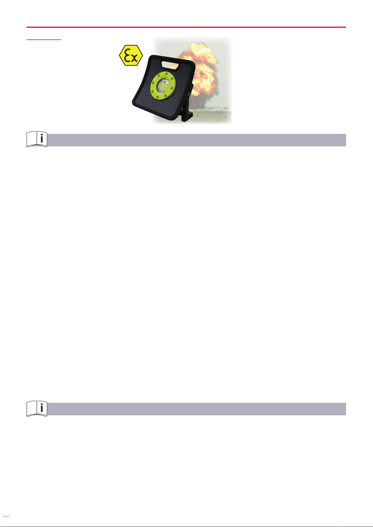
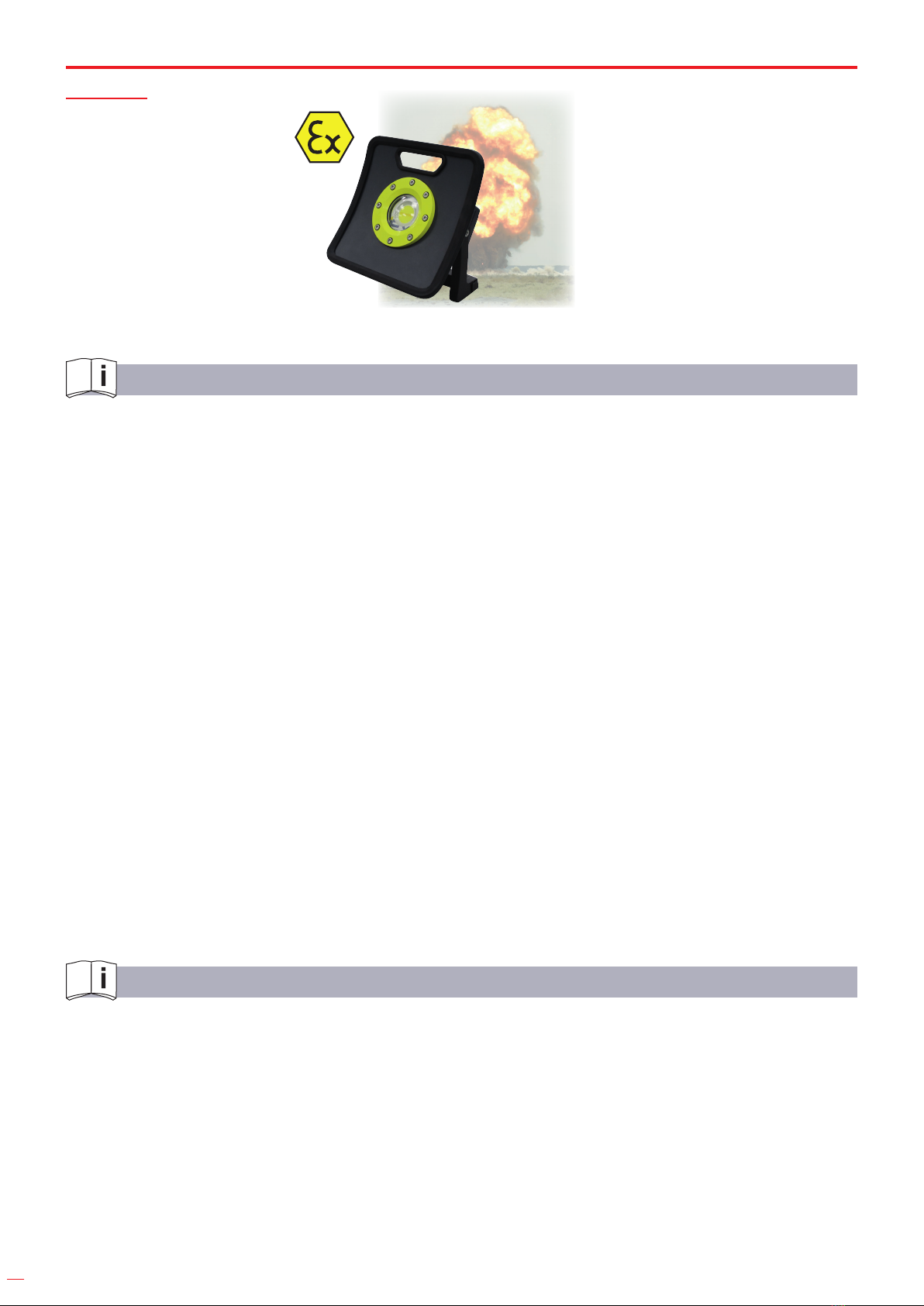
FOCO LED INTRÍNSECAMENTE SEGURO
INTRINSICALLY SAFE LED HAND LAMP
PROJECTEUR LED INTRINSÈQUEMENT SÛR
2
RECORDATORIOS IMPORTANTES
• Por favor lea estas instrucciones antes de usar, hacer el mantenimiento o el servicio de los
focos led a prueba de explosión.
• El foco led a prueba de explosión debe ser utilizado por una persona con formación
profesional.
• Para realizar el mantenimiento deben utilizarse las piezas de repuesto producidas o
designadas por el fabricante. Asegúrese de que el mantenimiento y el servicio no están
localizados en un lugar peligroso y que son realizadas por un profesional entrenado a tal
efecto. El uso de piezas no fabricadas por el fabricante afectará al desempeño de las de los
focos led a prueba de explosión.
• Los focos led a prueba de explosión deben cumplir con las disposiciones legales y
reglamentarias pertinentes de la Unión Europea.
¡ADVERTENCIA!
• ¡No abrir si está en presencia de una atmósfera explosiva!
• ¡No cargue la batería en lugares peligrosos!
• ¡No reemplace la batería en presencia de una atmósfera explosiva!
¡ADVERTENCIA!
Paquete de baterías:
• Utilice únicamente el paquete de baterías del fabricante.
• Utilicesolamenteelpaquetedelcargadorconlaespecicacióndelaentrada:AC100-240V/
50-60Hz0.8A.Salida:21.6V1A.
• Utilizar piezas de otras procedencias puede reducir el nivel de seguridad intrínseca de las
lámparas a prueba de explosión. Asegúrese de realizar la carga en un entorno libre de
peligros.
1. ESTÁNDAR
IEC60079-0:2011Atmósferasexplosivas,Par0:Equipo,Requisitosgenerales.
IEC60079-1:2014Atmósferasexplosivas,Par1:Proteccióndeequiposmediantecubiertas
antideagrantes.
IEC60079-7:2015Atmósferasexplosivas,Par7:Proteccióndelequipomediantemayor
seguridad “e”.
IEC60079-18:2014Atmósferasexplosivas,Par18:Proteccióndelequipomediantetipode
protección “m”.
IEC60079-11:2011Atmósferasexplosivas,Par11:Proteccióndelequipomediante
seguridad intrínseca “i”.
ESPAÑOL
3
IEC60079-28:2014Atmósferasexplosivas,Par28:proteccióndeequiposydesistemasde
transmisión mediante el uso de radiación óptica.
IEC60079-31:2013Atmósferasexplosivas,Par31:Equipodeproteccióndepolvos
inamablesmediantecubierta“t”.
IEC60529:2001Gradosdeprotecciónproporcionadosporcubiertas(códigoIP).
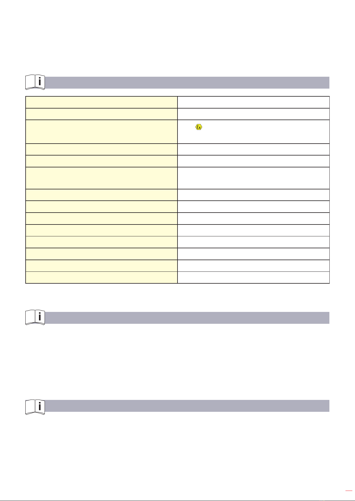
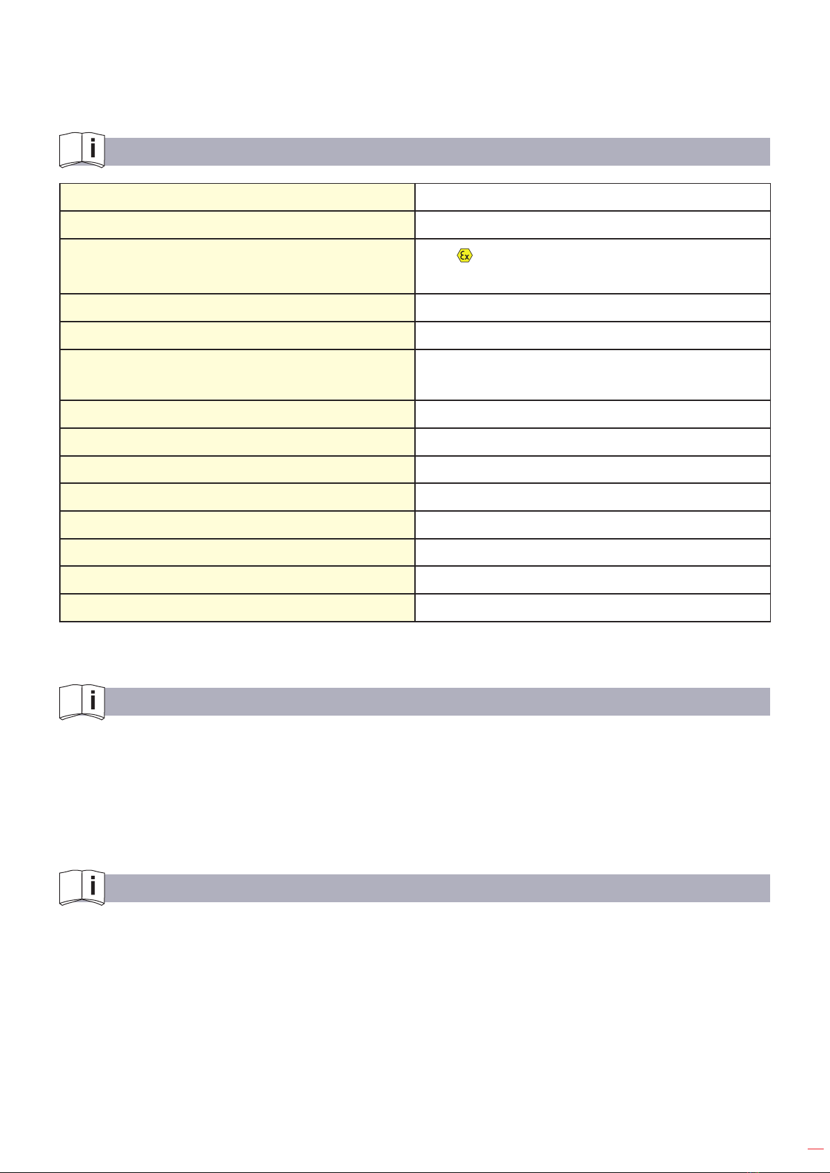
2. CARACTERÍSTICAS
Potencia nominal 14W
Zona peligrosa Zona1,Zona2/Zona21,Zona22
Símbolo de a prueba de explosión II2GExdbebmbopisIICT4Gb
II2DExtbIIICT85°CDbIP65
Flujo luminoso Alto1500lm
Cargador DC21.6V1A
Tipo y capacidad de la batería 19.2V/1400mAh26.88Wh
(Fosfatodelitioyhierro)
Tiempo de trabajo Alto2h
CRI (Ra) >80
CCT 5500K~6500K
IPXX IP65
Temperatura de operación (°C) -20°C~+45°C
Temperatura de almacenamiento (°C) -20°C~+45°C
Dimensión del producto L271xW266xH130mm
Peso del Producto 3,95kg
3. USO Y ALCANCE DE LA APLICACIÓN
ElfocoleddetrabajoesidóneoparaelusoenáreaexplosivadelaZona1,Zona2,Zona21,
Zona22,grupodegasIIA/IIB/IIC,grupodepolvoIIIA/IIIB/IIICyelGrupodeTemperaturaT1~
T4/T85°C.Esidóneoparausarenlailuminaciónlocal,auxiliarytemporalyparalailuminación
local principal de las industrias de productos de petróleo, fundición, químicos, farmacéuticos,
cerveceras, reservas militares, etc.
4. ESTRUCTURA
• Lacavidadapruebadeexplosionesqueincluyelafuentelumínicapegadaalasuperciede
contacto no puede ser reparada si ocurre algún daño o grieta.
• Las roscas de la cavidad a prueba de explosiones de la pieza del interruptor no pueden ser
reparadas si ocurre algún daño o grieta.
• La parte del cilindro de la cavidad a prueba de explosiones de la pieza del interruptor no
puede ser reparada si ocurre algún daño o grieta.

4
5. INSTRUCCIONES
• Antes de usar, compruebe si el embalaje está en buenas condiciones, si hay algún daño
visibleenelfocoledyenelcargador.Conrespectoalujolumínico,compruebesihay
cualquier daño visible en la estructura o algún “sonido anormal” en el interior. Por favor, abra
el foco led para comprobar si el daño puede afectar al rendimiento de la prueba de explosión
y realizar el tratamiento adecuado.
• Porfavor,compruebesilosparámetrosdelaplacadeidenticacióndelfocoledapruebade
explosión listados, se ajustan a las condiciones de uso reales.
• Elfocoledapruebadeexplosiones,conlafuncióndeajustedelángulode0-180ofreceuna
variedad de ángulos de orientación de la iluminación.
• Elfocoledapruebadeexplosióntienetresmodos:Low,HighyOFF.PresioneprimeroLow
(inferior),ensegundolugarHigh(alto),yentercerlugarOFF(APAGADO).
• Lapiezadepotenciaestásellada.Dejedeusarelfocoledcuandoelmaterialdeselladode
fundición se vuelva blando, se rompa o se dilate.
• Duranteelcableado,asegúresedequeeneldispositivoprincipaldelcablenofaltenel
anillo sellador, el anillo de retención y la tuerca de compresión. El cable que pasa a través
deldispositivoprincipaldebeestarconectadoatierra.Aprietenalmentelatuercade
compresión.
• Están prohibidas las siguientes operaciones en cualquier área peligrosa:
-Abrirelfocoledcuandoestétrabajandoosisehaapagadolacarga.
-Mantenimientoyreparaciónregularesuocasionales.
• Las personas que usan el foco led deben conocer el funcionamiento del foco led a prueba de
explosiones. Apague la luz a tiempo y evacúe el área peligrosa cuando encuentre cualquier
fenómenoanormal.Laspersonasnocualicadasnotienenpermitidorealizarlareparación
de los focos led a prueba de explosiones.
6. MANTENIMIENTO
• Los técnicos de servicio deben tener la formación adecuada de su puesto de trabajo
paraconocerlaespecicaciónyelfuncionamientooperativodeunfocoledaprueba
deexplosiones.Debentenerconocimientosprofesionalesyestarfamiliarizadosconla
estructura de los focos led a prueba de explosiones.
• Limpie regularmente el polvo y la suciedad de la carcasa del foco led a prueba de
explosionesparamejorarlaecacialuminosayelrendimientodeladispersióntérmica.Para
la limpieza se puede utilizar un paño húmedo.
• Compruebesilaspiezastransparenteshansidoimpactadasregularmenteporcuerpos
extraños.Compruebesilostornillosyloscomponentesinternosestánsueltos,tienenla
soldaduradañadaoestáncorroídos.Encasoarmativo,nolosutilicehastaquesehayan
reparado.
• Siutilizaelfocoledenunambientehúmedo,compruebeycambieregularmentelos
componentes del sellado para asegurar la función protectora de la carcasa.
• Cuandoelmaterialdelfundidodelselladosevuelvablando,seagrieteysedilatedeforma
obvia, cambie inmediatamente la energía.
• El anillo sellador, el anillo de retención y la tuerca de compresión en el dispositivo del cable
principal no pueden omitirse, ni se puede pasar por alto el ensamblaje de ninguna de sus
partes o ser desechados fácilmente.
• Cuandodesmonteelfocoled,debecumplirconlosrequisitosdeadvertenciaparaoperaren
áreas no peligrosas.
• Despuésdeabrirlacarcasa,debecomprobarsiloscomponentesdeselladosehanvuelto
5
duros o adhesivos; si la capa aislante del alambre está de color verde o carbonizada o si las
piezas aislantes y los componentes eléctricos se han deformado o presentan quemaduras.
Siestosucede,elfocoleddebeserreparadoinmediatamente.
• Elmodelo,laespecicación,ladimensiónyelrendimientodelaspiezasparael
mantenimiento deben mantenerse igual que los originales.
• Antes de cerrar la carcasa, utilice un repuesto, tipo aceite antioxidante, en las roscas a
prueba de explosivos, y compruebe si el anillo sellador está en su ubicación original para
lograr la función de sellado al cerrar la carcasa.
• Nodesmontelaspiezasdeselladodelfocoledconfrecuencia.Delocontrario,lafuncióna
prueba de explosión se verá afectada.
7. CONDICIONES ESPECIALES PARA UN USO SEGURO
• Lasreparacionesdelasjuntasantideagrantessólopuedenserrealizadasporelfabricante
o en nombre del fabricante y bajo su propia responsabilidad. Las reparaciones de acuerdo
conlosvaloresdelastablas1y2delaIEC60079-1noseránaceptadas.
• Lossujetadoresrelacionadosconlasjuntasantideagrantesdeberántenerunaclasede
resistenciadealmenosA2-70.
• Eltoquedelostornillosdelacajadeterminalesdebeestarenelrangode22±2kgf.
• Durantelainstalación,elusoyelmantenimiento,debenobservarselasnormasIEC60079-
10,IEC60079-14,IEC60079-17eIEC60079-19.
• Operandoenunaatmósferaexplosiva,elcasquillodeproteccióndelcargadordebeestar
bien apretado, no abra el casquillo de protección en una atmósfera explosiva.
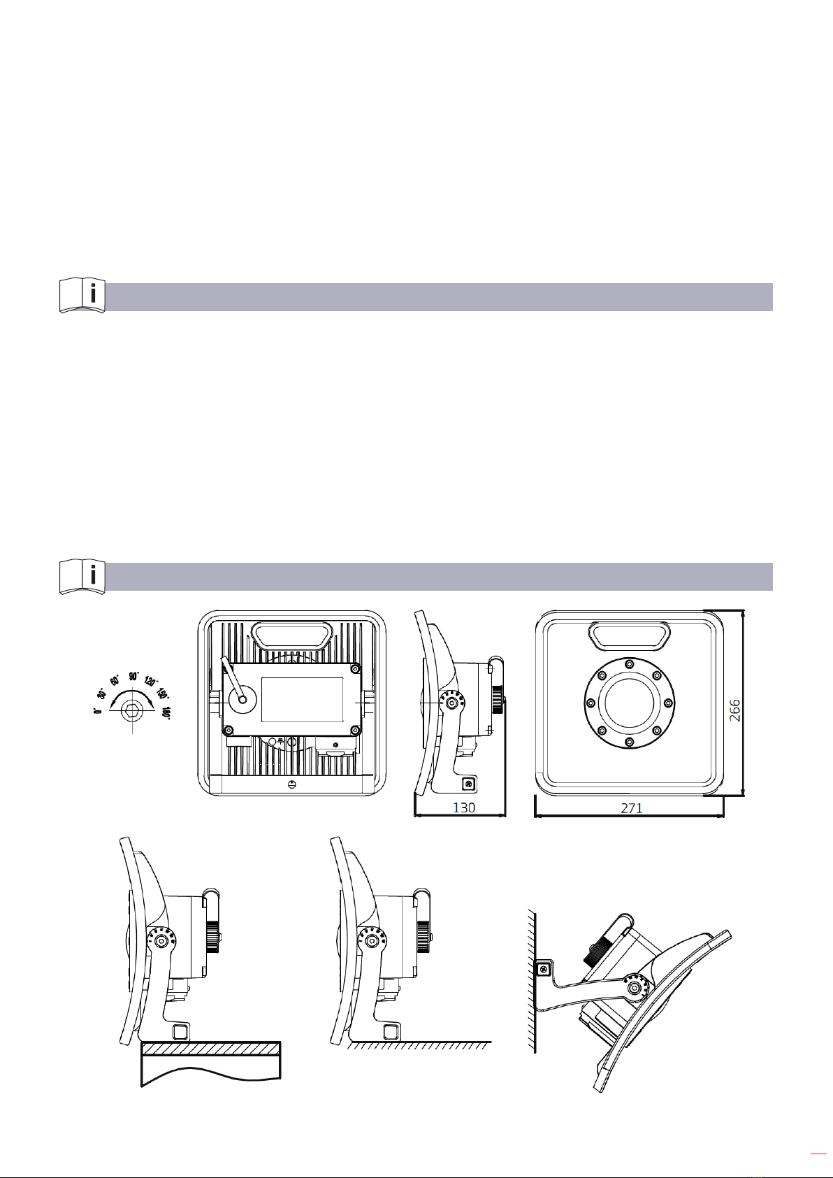
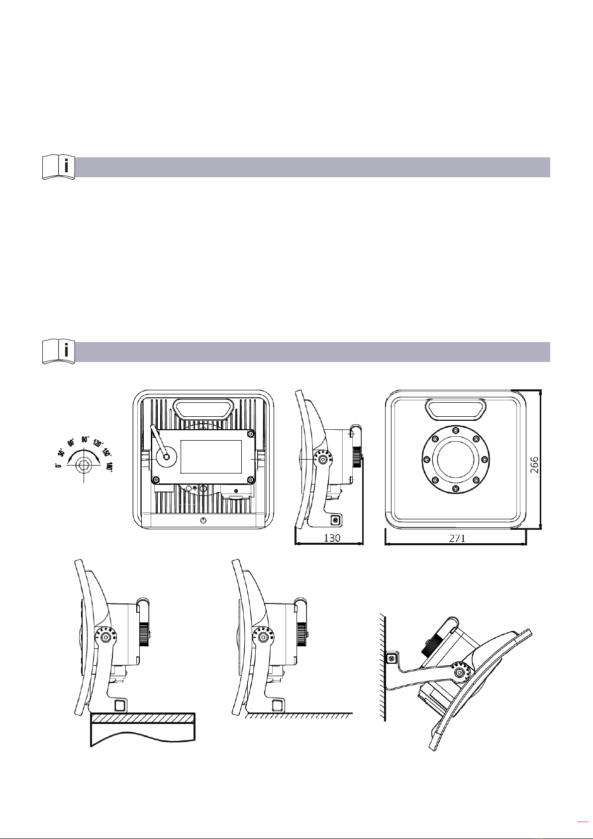
8. DIMENSIONES EXTERNAS Y DIAGRAMA DE INSTALACIÓN
Rangode
ángulo
ajustable
Instalación de
la plataforma Instalación de
pared
Base
6
IMPORTANT REMINDERS
• Pleasereadthisinstructionbeforeanyuse,maintenanceandserviceofexplosion-proof
lights.
• Theexplosion-prooflightmustbeusedbyacertainprofessionaltrainingperson.
• Mustusethereplacementpartswhichproducedorappointedbythemanufacturerfor
maintenance.
Makesurethemaintenanceandservicearenotinadangerousplaceandfullledby
professional trained person. Using the parts which not manufactured by the manufacturer will
destroytheexplosion-proofperformanceoftheexplosion-prooflights.
• Theexplosion-prooflightsshouldcomplywiththerelevantlawsandregulationsofthe
European Union.
WARNING!
• Donotopenwhenanexplosiveatmosphereispresent!
• Donotchargethebatteryinhazardouslocation!
• Donotreplacebatterywhenanexplosiveatmosphereispresent!
WARNING!
BatteryPack:
• Onlyusethebatterypackfromthemanufacturer.
• OnlyusethechargerpackwithspecofInput:AC100-240V/50-60Hz0.8AOutput:21.6V1A
• Usingothersourcespartsmaylowertheintrinsicsafetyleveloftheexplosion-prooflights.
Makesurecharginginnon-dangerousenvironment.
1. STANDARD
IEC60079-0:2011Explosiveatmospheres,Par0:Equipment,Generalrequirements
IEC60079-1:2014Explosiveatmospheres,Par1:Equipmentprotectionbyameproof
enclosures ”d”
IEC60079-7:2015Explosiveatmospheres,Par7:Equipmentprotectionbyincreasedsafety”e”
IEC60079-18:2014Explosiveatmospheres,Par18:Equipmentprotectionbytypeof
protection ”m”
IEC60079-11:2011Explosiveatmospheres,Par11:Equipmentprotectionbyintrinsicsafety”i”
IEC60079-28:2014Explosiveatmospheres,Par28:protectionofequipmentandtransmission
systems using optical radiation
ENGLISH
7
IEC60079-31:2013Explosiveatmospheres,Par31:Equipmentdustignitionprotectionby
enclosure”t”
IEC60529:2001Degreesofprotectionprovidedbyenclosure(IPcode).
2. CHARACTERISTICS
Power Rating 14W
Dangerous Area Zone1,Zone2/Zone21,Zone22
Explosion-proof Symbol II2GExdbebmbopisIICT4Gb
II2DExtbIIICT85°CDbIP65
Luminous Flux High1500lm
Charger DC21.6V1A
Battery Type and Capacity 19.2V/1400mAh26.88Wh
(Lithiumironphosphate)
Working Time High2h
CRI (Ra) >80
CCT 5500K~6500K
IPXX IP65
Operation Temperature (°C) -20°C~+45°C
Storage Temperature (°C) -20°C~+45°C
Product Dimension L271xW266xH130mm
Product Weight 3,95kg
3. USAGE AND APPLICATION SCOPE
TheintrinsicallysafeledhandlampissuitableforusinginexplosiveareaofZone1,Zone2,
Zone21,Zone22,gasgroupIIA/IIB/IIC,dustgroupIIIA/IIIB/IIICandTemperatureGroupT1~T4/
T85°C.Itissuitableforusingintemporarylocalauxiliarylightingandlocalmainlightingforthe
industries of petroleum produce, smelting, chemical, pharmaceutical, brewing, military reserve,
etc.
4. STRUCTURE
• Explosion-proofcavitywhichincludesthelightsourcegluingcontactsurfacecannotbe
repairedifanydamageorcrackhappens.
• Thethreadsofexplosion-proofcavityfortheswitchpartcannotberepairedifanydamageor
crackhappens.
• Thecylinderpartofexplosion-proofcavityfortheswitchpartcannotberepairedifany
damageorcrackhappens.

8
5. INSTRUCTION
• Beforeuse,pleasecheckwhetherthepackingisingoodcondition,ifthereisanyvisible
damageofthelightandcharger.Fortheoodlight,pleasecheckifthereisanyvisible
damageofthestructureor“abnormalsound”inside.Pleaseopenthelighttocheckifthe
damagewillinuencetheexplosion-proofperformanceandmakeappropriatetreatment.
• Pleasecheckiftheexplosion-prooflightnameplateparameterslistedareconformedtothe
actual conditions of use.
• Theexplosion-prooflightiswithangleadjustingfunctionfrom0°-180°tomeetavarietyof
angle lighting orientation.
• Thepowerpartiscastsealed.Stopusethelightwhenthecastsealingmaterialturnsoft,
crackandexpand.
• Theexplosion-prooflightiswithswitchmodeDim-Middle-High-OFF.Pressonce“Dim”,twice
“Middle”,third“High”,forth“OFF”.Thecorrespondingworkingtimeis4h,2h.
• Pleasechargethelightunderthecircumstancebetween0°Cto+45°C.Whenchargethe
battery,thetwopairofjointsareprovidedwithanti-reverseconnectionpositioningslots.
Please open the protective cover, insert the charging connector to the charging base and
screwthebuttcaptightly.Pleasepayattentiontothechargingorders:rstlymakesurethe
reliableconnectionbetweenthechargingbaseandjoint.Thenplugthechargerto
ACpowersupply.Theconversedoperationisprohibited.
• Theexplosion-prooflightiswiththefunctionofbatterycapacityindicating.Whencharging,
thebatteryindicatoris“red”.Whenitturns“green”,thechargingisnishedandplease
disconnecttheACpowersupply.
• Thefollowingoperationsareprohibitedinanypossibledangerousarea:
Openthelightwhenitisworkingorturningotheload.
Regularoroccasionalmaintenanceandrepair.
• Thepersonswhousethelightatsiteshouldknowabouttheperformanceofexplosion-proof
light.Turnothelightintimeandevacuatethedangerousareawhenndanyabnormal
phenomenon.Unqualiedrepairpersonisnotallowedtorepairtheexplosion-prooflights.
6. MAINTENANCE
• Theservicemanmusthaveon-the-jobtrainingtoknowthespecicationandoperating
performanceofexplosion-prooflight.Theymusthaveprofessionalknowledgeandshould
familiarwiththestructureofexplosion-prooflight.
• Cleanthedustanddirtontheshelloftheexplosion-prooflightregularlytoimprovethe
luminousecacyandheatdispersionperformance.Awetclothcanbeusedforcleaning.
• Checkwhetherthetransparentpartshavebeenimpactedbyforeignbodyregularly.Check
whetherthefastenersandinnercomponentsareloose,solderingoorcorroded.Ifyes,do
not use it until maintained.
• Ifusethelightindampenvironment,pleaseregularlycheckandchangethesealing
components to ensure the protective performance of the shell.
• Whendisassemblethelight,mustcomplywiththewarningrequirementstooperateinnon-
dangerous area.
• Whenthecastsealingmaterialturnsoft,crackandexpandobviously,pleasechangethe
power immediately.
• Afteropentheshell,shouldcheckwhetherthesealingcomponentsbecomehardor
adhesive; whether the insulating layer of the wire become green or carbonized; whether
the insulating parts and electrical components become deformed or have scorch. If these
problems are found, must repair the light immediately.
9
• Themodel,specication,dimensionandperformanceofthepartsformaintainingshould
keepthesameastheoriginalones.
• Beforeclosingtheshell,shouldusereplacementtypeantirustoilontheexplosive-proof
threadsandcheckwhetherthesealingringisattheoriginallocationbyachievethesealing
function when close the shell.
• Donotdisassemblethesealingpartsofthelightoften.Otherwisetheexplosive-prooffunction
willbeaected.
7. SPECIAL CONDITION FOR SAFE USE
• Repairsoftheameproofjointsmayonlybemadebythemanufactureroronbehalfofthe
manufacturerandonhisownresponsibility.Repairincompliancewiththevaluesintables1
and2ofIEC60079-1isnotaccepted.
• FastenersrelatedwithameproofjointsshallhavepropertyclassatleastA2-70.
• Thetoqueforthescrewsoftheterminalboxshallbeintherangeof22±2kgf.
• Wheninstallation,useandmaintenance,observefollowingstandardsIEC60079-10,
IEC60079-14,IEC60079-17andIEC60079-19.
• Operatingunderexplosiveatmosphere,protectioncapofchargermustbetightened,donot
open the protection cap under explosive atmosphere.
8. EXTERNAL DIMENSION AND INSTALLATION DIAGRAM
Adjustable
angle
range
Platform
installation Wall
installation
Ground

10
RAPPELS IMPORTANTS
•Mercidebienvouloirlirecesinstructionsavanttouteutilisation,entretienetservicedes
lampesantidéagrantes.
•Lalampeantidéagrantedoitêtreutiliséepardesprofessionnelsformés.
• Pour l’entretien, vous devez utiliser les pièces détachées fabriquées ou désignées par le
fabricant.
Assurez-vousquel’entretienetlesservicesnesefontpasdansunendroitdangereuxet
qu’ils sont exécutés par des professionnels formés. L’utilisation de pièces non fabriquées par le
fabricantanéantiraitlaperformanceantidéagrantedeslampesantidéagrantes.
•Leslampesantidéagrantesdoiventrespecterlesloisetrèglementsdel’UnionEuropéenne
en vigueur.
AVERTISSEMENT!
• Ne pas ouvrir dans une atmosphère explosive !
• Ne pas charger la batterie dans un endroit dangereux !
• Ne pas remplacer la batterie dans une atmosphère explosive !
AVERTISSEMENT!
Blocbatterie:
• Utilisez exclusivement le bloc batterie du fabricant.
•Utilisezexclusivementleblocchargeuraveclesspécicationsd’Entrée:AC100-240V/50-
60Hz0,8A.Sortie:21,6V1A.
• L’utilisation de pièces d’autres sources peut diminuer le niveau de sécurité intrinsèque
deslampesantidéagrantes.Assurez-vousd’eectuerlarechargedansunenvironnementne
présentant aucun danger.
1. NORME
CEI60079-0:2011Atmosphèresexplosives,Partie0:Matériel¸Exigencesgénérales.
CEI60079-1:2014Atmosphèresexplosives,Partie1:Protectiondumatérielparenveloppes
antidéagrantes.
CEI60079-7:2015Atmosphèresexplosives,Partie7:Protectiondumatérielparsécurité
augmentée « e ».
CEI60079-18:2014Atmosphèresexplosives,Partie18:Protectiondumatérielpar
encapsulage « m ».
CEI60079-11:2011Atmosphèresexplosives,Partie11:Protectiondumatérielparsécurité
intrinsèque « i ».
FRANÇAIS

11
CEI60079-28:2014Atmosphèresexplosives,Partie28:Protectiondumatérieletdes
systèmes de transmission utilisant le rayonnement optique.
CEI60079-31:2013Atmosphèresexplosives,Partie31:Protectioncontrel’inammationde
poussières par enveloppe « t ».
CEI60529:2001Degrésdeprotectionprocurésparlesenveloppes(CodeIP).
2. CARACTÉRISTIQUES
Données de puissance 14W
Zone dangereuse Zone1,Zone2/Zone21,Zone22
Symbole antidéflagrant II2GExdbebmbopisIICT4Gb
II2DExtbIIICT85°CDbIP65
Flux lumineux Élevé1500lm
Chargeur DC21.6V1A
Type et capacité de la batterie 19.2V/1400mAh26.88Wh
(Lithiumferphosphate)
Temps de fonctionnemen Élevé2h
IRC (Ra) >80
TCP 5500K~6500K
IPXX IP65
Température de fonctionnement (°C) -20°C~+45°C
Température de stockage (°C) -20°C~+45°C
Dimension du produit L271xW266xH130mm
Poids du produit 3,95kg
3. UTILISATION ET CHAMP D’APPLICATION
ProjecteurdechantierCA(abréviélampeantidéagrantedanslesinstructionssuivantes)
convientpouruneutilisationdanslesenvironnementsexplosifsdesZone1,Zone2,Zone
21,Zone22,groupepourlegazIIA/IIB/IIC,groupepourlapoussièreIIIA/IIIB/IIICetgroupe
detempératureT1~T4/T85°C.Ilpeutêtreutilisécommeéclairagecomplémentairelocalet
provisoire et comme éclairage principal local pour les industries de production pétrolière, de
fusion, chimiques, pharmaceutiques, brassicoles, les réserves militaires, etc.
4. STRUCTURE
• Lacavitéantidéagrantequicomprendlasurfacedecontactcollantedelasourcelumineuse
nepeutpasêtreréparéeencasdedommageoudessure.
• Leletagedelacavitéantidéagrantepourlecommutateurnepeutpasêtreréparéencas
dedommageoudessure.
• Lapartiecylindriquedelacavitéantidéagrantepourlecommutateurnepeutpasêtre
réparéeencasdedommageoudessure.

12
5. INSTRUCTIONS
• Avantutilisation,mercidevérierquel’emballageestenbonétatetqu’iln’yapasde
dommagevisiblesurlalampeetlechargeur.Pourleprojecteur,mercidevériers’ilyades
dommagesvisiblesdelastructureoudes«bruitsanormaux»àl’intérieur.Veuillezouvrirla
lampepourvériersiledommagepeutavoiruneetsurlaperformanceantidéagranteet
procéder au traitement approprié.
• Mercidevériersilesparamètresdelaplaquesignalétiquedelalampeantidéagrantesont
conformesauxconditionseectivesd’utilisation.
• Lalampeantidéagranteestdotéed’unefonctionderéglagedel’angleallantde0à180an
de répondre à une grande variété d’angles d’orientation de l’éclairage.
• LalampeantidéagranteestdotéedetroismodesBas,Élevé,ARRÊT.Appuyezunefois
pourBas,deuxfoispourÉlevé,troisfoispourARRÊT.
• Lapartied’alimentationestscelléeparmoulage.Cessezd’utiliserlalampelorsquele
matériaudescellageparmoulagedevientmou,sessureous’élargit.
• Lorsducâblage,vériezbienlaprésencedelabagued’étanchéité,del’anneauderetenue
et de l’écrou de compression dans le dispositif de guidage des câbles. Le câble qui passe
parledispositifdeguidagedoitêtrereliéàlaterre.Pournir,serrezl’écroudecompression.
• Les opérations suivantes sont interdites dans toute zone potentiellement dangereuse :
Ouvrirlalampelorsqu’ellefonctionneouéteindrelacharge.
Entretien régulier ou occasionnel et réparation.
• Lespersonnesquiutilisentlalampesurlechantierdoiventêtreinforméesdelaperformance
delalampeantidéagrante.Éteignezimmédiatementlalampeetévacuezlazone
dangereuselorsquevousconstatezunphénomèneanormal.Lespersonnesnonqualiées
pourlaréparationnesontpasautoriséesàréparerleslampesantidéagrantes.
6. ENTRETIEN
• La personne en charge de l’entretien doit avoir une formation pratique et connaître les
spécicationsetlesperformancesopérationnellesdelalampeantidéagrante.Elledoit
avoir des connaissances professionnelles et bien connaître la structure de la lampe
antidéagrante.
• Enlevezrégulièrementlapoussièreetlasaletésurlacoquedelalampeantidéagrantean
d’optimiserl’ecacitélumineuseetlacapacitédedissipationdelachaleur.Vouspouvez
utiliserunchionhumide.
• Vériezrégulièrementsilespartiestransparentesontétéimpactéespardescorpsétrangers.
Vériezquelesxationsetlescomposantsinternesnesontpasdétachés,dessoudésou
corrodés. Le cas échéant, n’utilisez pas la lampe avant qu’elle n’ait été entretenue.
• Sivousutilisezlalampeenmilieuhumide,veuillezvérieretchangerrégulièrementles
composants de scellage pour garantir la performance de protection de la coque.
• Lorsquelematériaudescellageparmoulagedevientmou,sessureous’élargitdemanière
évidente, veuillez changer immédiatement l’alimentation.
• La bague d’étanchéité, l’anneau de retenue et l’écrou de compression dans le dispositif de
guidagedescâblesnepeuventpasêtresupprimés,nonassemblésoujetés.
• Lorsque vous désassemblez la lampe, vous devez vous conformer aux exigences en matière
d’avertissement pour travailler dans une zone ne présentant aucun danger.
• Aprèsavoirouvertlacoque,vériezsilescomposantsdescellagesontdursoucollants;si
lacoucheisolantedulestverteoucarbonisée;silespartiesisolantesetlescomposants
électriques sont déformés ou ont brûlés.
Sivousconstatezcesproblèmes,vousdevezréparerimmédiatementlalampe.

13
• Lemodèle,lesspécications,ladimensionetlaperformancedespiècespourl’entretien
doiventêtreidentiquesauxpiècesd’origine.
• Avantdefermerlacoque,nousvousconseillonsd’utiliserunehuileanti-rouillesurleletage
antidéagrantetdevérierquelabagued’étanchéitéestdanssonemplacementd’origine
anquel’étanchéitésoitparfaitelorsquevousfermezlacoque.
• Évitez de désassembler trop souvent les pièces d’étanchéité de la lampe. Le cas échéant,
celaaecteraitlafonctionantidéagrante.
7. CONDITION SPÉCIALE POUR UNE UTILISATION SANS RISQUE
•Lesréparationsdesjointsantidéagrantsnedoiventêtreeectuéesqueparlefabricantou
pour le compte du fabricant et à sa propre responsabilité. Les réparations en conformité avec
lesvaleursdestableaux1et2deCEI60079-1nesontpasacceptées.
•Ledispositifexternedeliaisonàlaterredoitêtreconnectédemanièreable.
•LesxationsliéesauxjointsantidéagrantsdoiventaumoinscorrespondreàA2-70.
•Lecoupledeserragedesvisdelaboîtederaccordementdoitêtredel’ordrede22±2kgf.
•Lorsdel’installation,del’utilisationetdel’entretien,merciderespecterlesnormesCEI
60079-10,CEI60079-14,CEI60079-17etCEI60079-19.
•Laconnexionàlasourced’alimentationdoitêtresituéedansunezonesécurisée.Sila
connexiondoitêtresituéedansleszonesEx,lesconnecteurscertiésoulaboîtedejonction
avecunenotesusantedoiventêtreutilisés.
8. DIMENSION EXTERNE ET SCHÉMA DE MONTAGE
Installation de
la plateforme Installation
des parois
Terre
Variation
d’angle
réglable

14


Table of contents
Languages:
Other EGAmaster Lighting Equipment manuals


Popular Lighting Equipment manuals by other brands


Vision & Control
Vision & Control LDLF30x420-R633/24V/-a installation guide

Somogyi Elektronic
Somogyi Elektronic home DL 210L instruction manual

Steren
Steren PAR-030 instruction manual

THORLABS
THORLABS DC3100 Series Operation manual

Philips
Philips RD6 installation instructions

olympia electronics
olympia electronics GR-423/12L/MAR quick start guide