EGAmaster 57669 User manual

MANUAL DE INSTRUCCIONES
OPERATING INSTRUCTIONS
MANUEL D’INSTRUCTIONS
ESPAÑOL............................... 3
ENGLISH................................ 9
FRANÇAIS ........................... 15
GARANTIA/GUARANTEE
GARANTIE........................... 21
MÁQUINA DE CALIBRACIÓN DE PAR
TORQUE CALIBRATION MACHINE
MACHINE D’ÉTALONNAGE DE COUPLE
COD.57669
Incluido / Included / Inclus 57650
medidor de par / torque tester / mesureur de couple
Accesorio opcional (no incluido) / Optional accessory (not
included) / Accessoire optionnel (non inclus) 57653 Software de
par de medición en tiempo real / Real time measurement torque
software / Software de mesure du couple en temps réel


3
ESPAÑOL
LEA DETENIDAMENTE ESTE MANUAL
ANTES DE USAR EL PRODUCTO
- Utilice única y exclusivamente para el uso previsto en este manual.
- No vulnere las seguridades de la máquina. Si hay alguna avería haga que se repare.
- Evite las zonas de posible atrapamiento.
- No sobrecargue la máquina.
- Vigile el estado de conservación de la máquina y de eventuales funcionamientos extraños.
NORMAS GENERALES DE USO
- Siga los procedimientos descritos en este manual.
- Utilice el banco de ensayos únicamente para la tarea diseñada.
- VIGILE EL ESTADO de conservación y los posible defectos que pueda tener.
- NO genere sobreesfuerzos en la máquina.
CONDICIONES DE INSTALACIÓN Y FUENTES DE ENERGÍA
Lamáquinadebecolocarsesobreunamesaampliayderesistenciasuciente,enun
entornosecoybieniluminadocomopuedeserunaocina.Laalturadelamesaesimportante
para la ergonomía del operario.
POTENCIA ELÉCTRICA
Únicamente para alimentación de los sensores:
- Monofásica 230VAC sobre enchufe macho común Schuko siempre mediante su
transformador suministrado con el conjunto.
ENERGÍA MECÁNICA
- Energía mecánica manual aportada por el usuario mediante manivela.
- Diseñada para trabajar en un entorno de interior (no húmedo).
- Máquina concebida para una temperatura de utilización entre 5°C y +35°C.
DESCRIPCIÓN DEL USO PREVISTO
Estámáquinaestádiseñadaparainstalarseenunasinstalacionestipoocinas,bien
iluminado,sobremesa,alimentadaaunenchufeschuko16Aconvencionaldeinstalación
domésticaodeocinaprotegidapormagnetotérmico<16Aydiferencialde30mA.

4
LOS PUNTOS SIGUIENTES DEBERÁN
OBLIGATORIAMENTE SER VERIFICADOS
Orden y Limpieza
La máquina debe tener los elementos accesorios propio mínimos. Utilice un paño de
algodón para limpiarla y en caso de suciedad ligeramente humedecido en agua jabonosa.
Placa identicativa presente y legible
Modelo,fabricante,nºserie,fechafabricación.
Desgaste
- No deben apreciarse ruidos extraños en los movimientos.
- Laestructurabatientedeberotarplana,sincabeceos.
- La manivela debe girar entre topes suavemente y sin chirridos
- La Tapa de seguridad debe estar integra y cerrar correctamente.
Mantenimiento mecánico
El SISTEMA de husillo debe ser limpiado con un trapo limpio y engrasado en caso de
detectar ruidos o resistencia aunque probablemente no requiera ser lubricada nunca. El eje no
requiere engrase.
Deformación
No deben apreciarse deformaciones permanentes ni FISURAS.
Corrosión
Nopuedehabercorrosión.Esunamáquinaparausoenocinaenentornoseco.
Ante la duda contacte con el fabricante para su revisión y mantenimiento.
MAL USO RAZONABLEMENTE PREVISIBLE
- NO utilice esta máquina para ensayos que no corresponden al uso previsto.
- NO utilice la máquina si duda de su estado.
- NO vulnere las protecciones de seguridad ni utilice la máquina sin que estén activas.
- NO sobrecargue la máquina ni los sensores. Tenga en cuenta los rangos de los sensores.

5
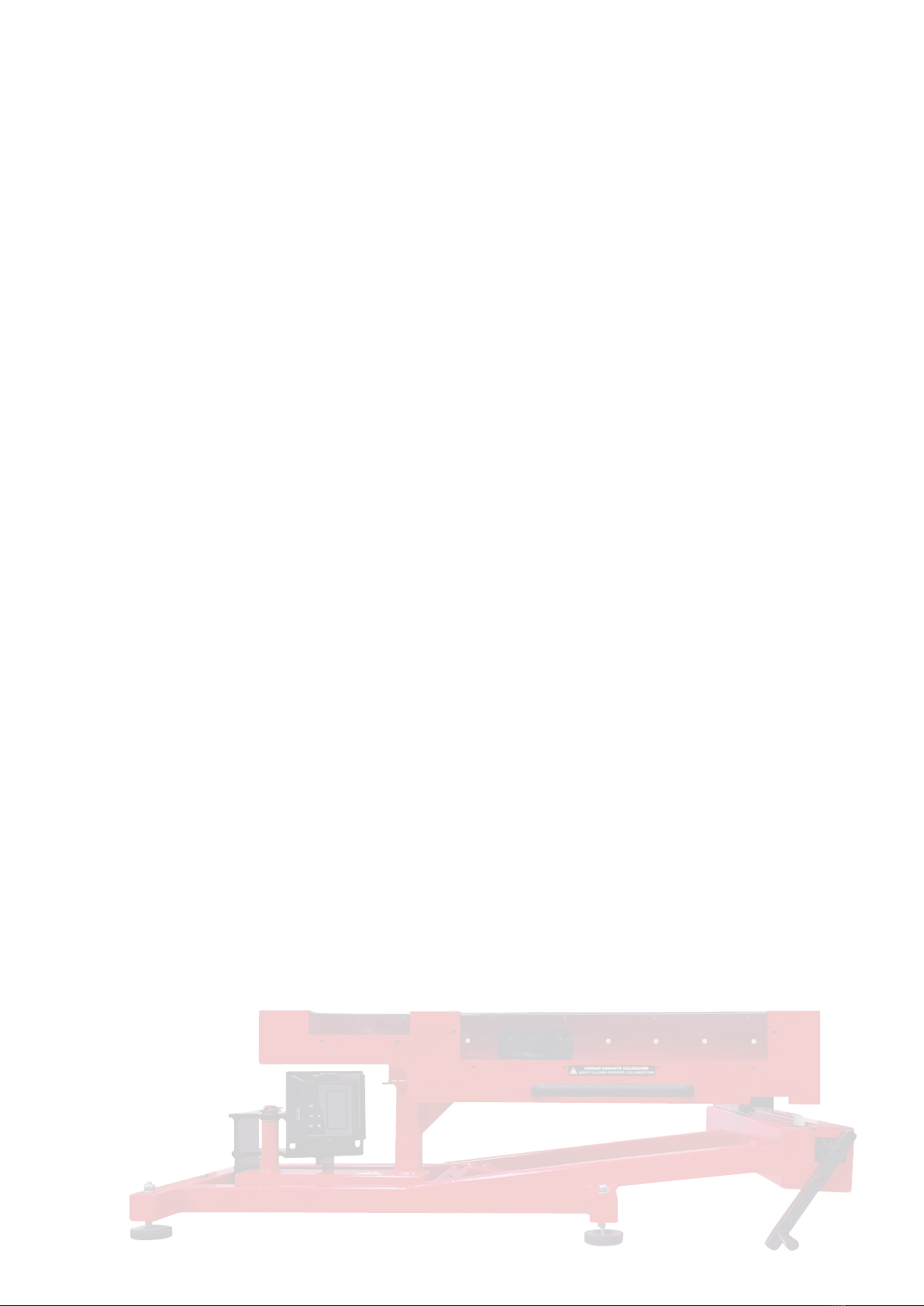
PARTES DE LA MÁQUINA DE CALIBRACIÓN DE PAR
1 3
6789
5
4
10
2
1medidordepar57650
2empujador
3tapa de seguridad
4alojamiento para la llave
dinamométrica
5husillo
6manivela
7apoyo
8 bancada
9eje de rotación
10 útil para calibración
sentido antihorario
Junto con la máquina de calibración se entregan:
-1UnidadCOD.RA177tacodenylon.
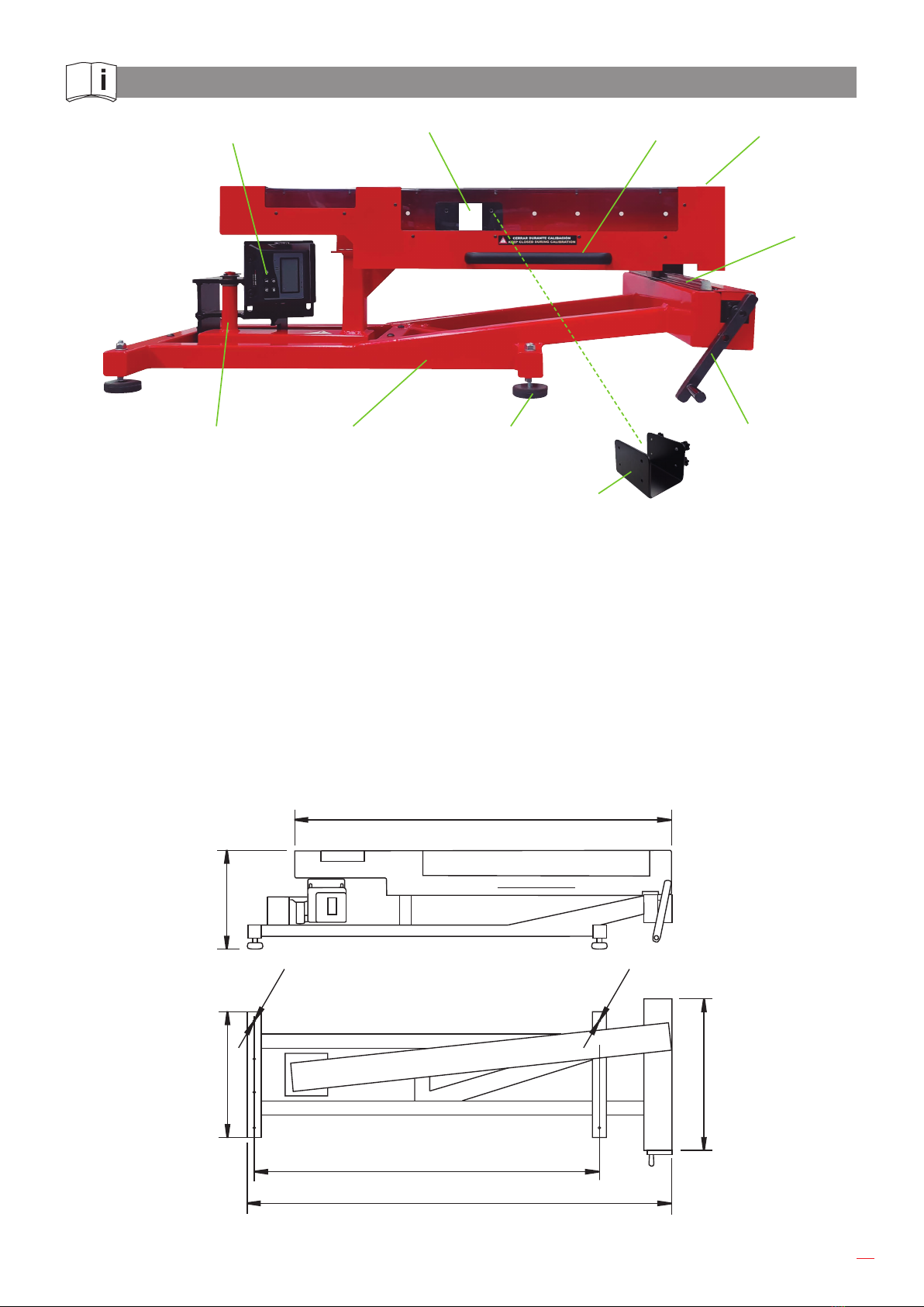
445
1257
1100
810
800
600
Ø11
Ø11
Las medidas indicadas deben tomarse como referencia.

6
GUÍA RÁPIDA DE USO
Antes de comenzar la calibración:
- la llave dinamométrica no debe estar cargada.
- el extremo derecho del alojamiento para la llave dinamométrica
debe estar situado en el extremo trasero del husillo (desplazarlo
hacia atrás con la manivela).
1. Encenderelmedidordepar(COD.57650MedidordeparSQ1/2''___35-350Nm).
- Pulsar Cpara encender el medidor de par.
- Seguido presionar para poner a 0 el medidor de par antes de usarlo.
Para obtener más información sobre medidores de par
consulte instrucciones en: www.egamaster.com
2. Abra la tapa de seguridad para proceder a la colocación de la llave dinamométrica.
3. Coloque la llave dinamométrica. Es posible que se requiera el uso de un adaptador para
conectar el accionamiento cuadrado de la llave dinamométrica con el medidor.
4. La llave dinamométrica debe colocarse en posición horizontal.
Utilizar un taco de nylon para dejar la llave dinamométrica horizontal
Posteriormente deslice horizontalmente el empujador g.2 (COD.RA177) de forma que
quede situado entre la parte trasera y el mango de la llave. Siempre irá colocado a la altura
demitaddelmango,queesdondeseencuentraelpuntodeaplicaciónparaconseguirasí
el par requerido.
Cierre la tapa de seguridad.
5. Asegúrense de que el medidor de par a utilizar esté encendido.
6. Alcomenzaragirarlamanivelahacialaderecha,carguelallave.Elgirodebeser
continuo hasta que la llave dinamométrica llegue al par seleccionado. En ese momento el
valordelparenelmedidorquedarájo.
Unavezquenalicelaprueba,tomenotadelvalordepardelapruebaindicadoenla
pantalla del medidor de par.
Gire la manivela hacia la izquierda hasta que la llave dinamométrica esté en posición libre
(sin carga).
En caso de calibración en sentido antihorario,colocarútilg.10 en el alojamiento de
la llave dinamométrica donde corresponda y seguir pasos anteriormente descritos para la
calibración.

7
3 4
5 6
12
Nota: Para realizar una prueba de calibración correcta, se recomienda seguir los
procedimientos estándar internacionales: por ejemplo, la norma internacional ISO 6789 o
similar.
MANTENIMIENTO
Mantenga el husillo bien engrasado.
Realice la calibración periódica del medidor de par.

8

9
ENGLISH
READ THIS MANUAL CAREFULLY
BEFORE USING THE PRODUCT
- Use only and exclusively for the use foreseen in this manual.
- Donotviolatethesafetyofthemachine.Ifthereisafault,haveitrepaired.
- Avoid areas of possible entrapment.
- Do not overload the machine.
- Check the state of conservation of the machine and any strange operations.
GENERAL RULES OF USE
- Follow the procedures described in this manual.
- Use the test bench only for the designed task.
- MONITOR THE STATE of conservation and the possible defects that it may have.
- DO NOT overstress the machine.
INSTALLATION CONDITIONS AND ENERGY SOURCES
Themachinemustbeplacedonawidetablewithsucientresistance,inadryandwell-
litenvironmentsuchasanoce.Theheightofthetableisimportantfortheergonomicsofthe
operator.
ELECTRIC POWER
Only for powering the sensors:
- Single-phase 230VAC on a common Schuko male plug always using its transformer
supplied with the set.
MECHANICAL ENERGY
- Manual mechanical energy supplied by the user by means of a crank.
- Designed to work in an indoor environment (not humid).
- Machine designed for a temperature of use between 5 °C and + 35 °C.
DESCRIPTION OF INTENDED USE
Thismachineisdesignedtobeinstalledinoce-typefacilities,welllit,onatable,powered
byaconventional16ASchukosocketfordomesticoroceinstallationsprotectedbya<16A
circuitbreakerand30mAdierential.

10
THE FOLLOWING POINTS MUST BE VERIFIED
Order and Cleanliness
he machine must have its own minimum accessory elements. Use a cotton cloth to clean it
andincaseofdirt,slightlymoistenedwithsoapywater.
Identication plate present and legible
Model,manufacturer,serialnumber,manufacturingdate.
Wear
- There should be no strange noises in the movements.
- Theswingstructuremustrotateat,withoutpitching.
- The crank should turn between stops smoothly and without squeaks.
- The safety cover must be integral and close properly.
Mechanical maintenance
The spindle SYSTEM should be cleaned with a clean and greased cloth in case of detecting
noiseorresistance,althoughitprobablyneverneedstobelubricated.Theshaftdoesnot
require greasing.
Deformation
There should be no permanent deformation or CRACKS.
Corrosion
Therecanbenocorrosion.Itisamachineforoceuseinadryenvironment.
If in doubt, contact the manufacturer for review and maintenance.
REASONABLY FORESEEABLE MISUSE
- DO NOT use this machine for tests that do not correspond to its intended use.
- DO NOT use the machine if you doubt its condition.
- DO NOT violate the safety protections or use the machine without them being active.
- DO NOT overload the machine or the sensors. Take into account the ranges of the sensors.

11
TORQUE CALIBRATION MACHINE PARTS
1 3
6789
5
4
10
2
1torquetester57650
2pusher
3safety cap
4torque wrench housing
5spindle
6handle
7support
8 bench
9axis of rotation
10 tool for CCW calibration
Together with the calibration machine are delivered:
-1UnitCOD.RA177nylonblock.
445
1257
1100
810
800
600
Ø11
Ø11
Indicated measuremente should be taken as reference.

12
QUICK USE GUIDE
Before starting the calibration:
- the torque wrench must not be loaded.
- the right end of the torque wrench housing must be at the rear
end of the spindle (move it backwards with the handle).
1. Turn on the torque tester(COD.57650Torque testerSQ1/2’’___35-350Nm).
- Press Cto turn on the torque tester.
- Often press to reset the torque tester before use.
For more information on torque testers
see instructions at: www.egamaster.com
2. Open the safety cover to proceed with the installation of the torque wrench.
3. Place the torque wrench in the position of the torque tester you will be using. The use of
an adapter may be required to connect the square drive of the torque wrench to the tester.
4. The torque wrench must be placed in a horizontal position.
Then slide the pusher g.2 (COD.RA177) horizontally so that it is located between the rear
part and the handle of the wrench. It will always be placed at the height of the middle of the
handle,whichiswheretheapplicationpointislocatedtoachievetherequiredtorque.
Close the safety cap.
5. Make sure the torque tester to be used is turned on.
6. Asyoustartturningthecranktotheright,loadthekey.Therotationmustbecontinuous
until the torque wrench reaches the selected torque. At that time the torque value on the
testerwillbexed.
Afterthetestiscomplete,makeanoteofthetesttorquevalueindicatedonthetorque
tester display.
Turn the crank counterclockwise until the torque wrench is in the free (no load) position.
In case of CCW calibration,placethetoolg.10 in torque wrench housing at required
position and follow previous procedure for calibration.

13
3 4
5 6
12
Remark: For making correct calibration test, it is advised to follow international
standard procedures: for example, international standard ISO6789 or similar.
MAINTENANCE
Keep the spindle well greased.
Perform periodic torque tester calibration.

14

15
FRANÇAIS
LISEZ ATTENTIVEMENT CE MANUEL
AVANT D’UTILISER LE PRODUIT
- Utiliseruniquementetexclusivementpourl’usageprévudanscemanuel.
- Neviolezpaslasécuritédelamachine.S’ilyaunproblème,faites-leréparer.
- Évitez les zones de piégeage possible.
- Ne surchargez pas la machine.
- Vérierl’étatdeconservationdelamachineetd’éventuellesopérationsétranges.
RÈGLES GÉNÉRALES D’UTILISATION
- Suivez les procédures décrites dans ce manuel.
- N’utilisezlebancd’essaiquepourlatâcheprévue.
- SURVEILLERL’ÉTATdeconservationetleséventuelsdéfautsqu’ilpeutprésenter.
- NE PAS trop solliciter la machine.
CONDITIONS D’INSTALLATION ET SOURCES D’ÉNERGIE
Lamachinedoitêtreplacéesurunegrandetableavecunerésistancesusante,dans
un environnement sec et bien éclairé comme un bureau. La hauteur de la table est importante
pourl’ergonomiedel’opérateur.
POUVOIR ÉLECTRIQUE
Uniquement pour alimenter les capteurs :
- Monophasé230VACsuruneprisemâleSchukocommuneenutilisanttoujoursson
transformateur fourni avec le kit.
ÉNERGIE MÉCANIQUE
- Energiemécaniquemanuellefournieparl’utilisateuraumoyend’unepoignée.
- Conçu pour fonctionner dans un environnement intérieur (non humide).
- Machineconçuepourunetempératured’utilisationcompriseentre5°Cet+35°C.
DESCRIPTION DE L’UTILISATION PRÉVUE
Cettemachineestconçuepourêtreinstalléedansdeslocauxdetypebureau,bienéclairée,
surunetable,alimentéeparunepriseSchukoclassique16Apourdesinstallationsdomestiques
oudebureauprotégéesparundisjoncteur<16Aetundiérentiel30mA.

16
LES POINTS SUIVANTS DOIVENT ÊTRE VÉRIFIÉS
Ordre et hygiene
Lamachinedoitavoirsespropresélémentsaccessoiresminimum.Utilisezunchionen
cotonpourlenettoyeretencasdesaleté,légèrementhumidiéavecdel’eausavonneuse.
Plaque d’identication présente et lisible
Modèle,fabricant,numérodesérie,datedefabrication.
Porter
- Il ne devrait y avoir aucun bruit étrange dans les mouvements.
- Lastructurepivotantedoitpivoteràplat,sanstangage.
- La poignée doit tourner entre les arrêts en douceur et sans grincements.
- Le couvercle de sécurité doit être intégré et se fermer correctement.
Maintenance mécanique
LeSYSTÈMEdebrochedoitêtrenettoyéavecunchionpropreetgraisséencasde
détectiondebruitouderésistance,mêmes’iln’aprobablementjamaisbesoind’êtrelubrié.
L’arbrenenécessitepasdegraissage.
Déformation
Il ne devrait y avoir aucune déformation permanente ou FISSURES.
Corrosion
Ilnepeutyavoirdecorrosion.C’estunemachineàutiliseraubureaudansun
environnement sec.
En cas de doute, contactez le fabricant pour examen et maintenance.
MAUVAISE UTILISATION RAISONNABLEMENT PRÉVISIBLE
- N’utilisezPAScettemachinepourdestestsquinecorrespondentpasàsonutilisation
prévue.
- N’utilisezPASlamachinesivousdoutezdesonétat.
- NEPASenfreindrelesprotectionsdesécuritéouutiliserlamachinesansqu’ellesnesoient
actives.
- NE surchargez PAS la machine ou les capteurs. Tenez compte des portées des capteurs.

17
PIÈCES DE MACHINE D’ÉTALONNAGE DE COUPLE
1 3
6789
5
4
10
2
1mesureurdecouple57650
2poussoirs
3couvercle de sécurité
4boîtier pour clé
dynamométrique
5broches
6poignée
7soutien
8 banc
9axe de rotation
10utilepourl’étalonnage
dans le sens antihoraire
Aveclamachined’étalonnagesontlivrés:
-1UnitéCOD.RA177taquetennylon.
445
1257
1100
810
800
600
Ø11
Ø11
La mesure indiquée doit être prise comme référence.

18
MANUEL RAPIDE D’UTILISATION
Avant de commencer l’étalonnage :
- a clé dynamométrique ne doit pas être chargée.
- l’extrémité droite du boîtier pour la clé dynamométrique doit être
à l’extrémité arrière de la broche. (déplacez-le vers l’arrière avec
la poignée).
1. Allumerlemesureurdecouple(COD.57650MesureurdecoupleSQ1/2’’___35-350
Nm).
- Appuyez Csur pour activer le mesureur de couple.
- Appuyez souvent pour réinitialiser le mesureur de couple avant utilisation.
Pour plus d’informations sur les mesureurs de couple,
voir les instructions sur: www.egamaster.com
2. Ouvrezlecouvercledesécuritépourprocéderàl’installationdelaclédynamométrique.
3. Placez la clé dynamométrique dans la position du mesureur de couple que vous
allezutiliser.L’utilisationd’unadaptateurpeutêtrenécessairepourconnecterlecarré
d’entraînementdelaclédynamométriqueaumesureur.
4. La clé dynamométrique doit être placée en position horizontale.
Utilizar un taco de nylon para dejar la llave dinamométrica horizontal
Faites ensuite coulisser le poussoir g.2 (COD.RA177)horizontalementanqu’ilse
positionneentrelapartiearrièreetlapoignéedelaclé.Ilseratoujoursplacéàlahauteur
dumilieudelapoignée,làoùsetrouvelepointd’applicationand’obtenirlecouplerequis.
Fermer le couvercle de sécurité.
5. Asegúrense de que el medidor de par a utilizar esté encendido.
6. Lorsquevouscommencezàtournerlapoignéeversladroite,chargezlaclé.Larotation
doitêtrecontinuejusqu’àcequelaclédynamométriqueatteignelecouplesélectionné.À
cemoment-là,lavaleurdecouplesurlemesureurseraxée.
Unefoisletestterminé,notezlavaleurducoupledetestindiquéesurl’écrandumesureur
de couple.
Tournerlapoignéedanslesensantihorairejusqu’àcequelaclédynamométriquesoiten
position libre (sans charge).
Danslecasd’unétalonnagedanslesens antihoraire,placerl’outilg.10danslesiège
delaclédynamométriqueàl’endroitoùilcorrespondetsuivrelesétapesprécédemment
décritespourl’étalonnage.

19
3 4
5 6
12
Remarque : Pour eectuer un test d’étalonnage correct, il est conseillé de suivre les
procédures standard internationales : par exemple la norme internationale ISO 6789 ou
similaire.
MAINTENANCE
Gardez la broche bien graissée.
Eectuerunétalonnagepériodiquedumesureurdecouple.

20
This manual suits for next models
1
Table of contents
Languages:
Other EGAmaster Test Equipment manuals