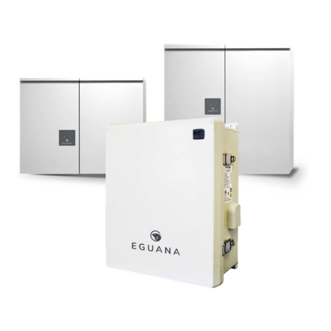
Eguana Enduro 0307 Installation manual

67020Rev3
Enduro 0307™
Installation & Startup Guide

IMPORTANT SAFETY INSTRUCTIONS!
SAVE THESE INSTRUCTIONS
This manual contains important instructions for the Enduro BESS Home Energy Storage System. The components
described by this manual are intended to be used as part of an Energy Storage system.
CAUTION: Hazardous Voltages! This inverter contains hazardous voltage that may be lethal. It may only be installed
by qualified personnel who have read this manual and are familiar with its operation and hazards. The following safety
procedures should be followed:
Only connect the system to a compatible electrical service as defined in the model specifications. The system must be
connected to a dedicated branch circuit in the main electrical panel.
CAUTION! This product contains high energy lithium batteries. Qualified and trained personnel should wear protective
clothing and equipment when working inside the battery cabinet and/or with battery modules.
This product is compatible with the LG Chem battery model EM048126P3S7 only.
CAUTION! The battery provided with this system must be charged only by the energy storage system. Do not
attempt to charge batteries with any other charger device or connect any devices directly to the DC battery bus.
Ensure proper electrical grounding in accordance with code requirements.
Ensure proper airflow path for active cooling.
Never operate system in a manner not described by this manual.
Only qualified personnel should service this product.
Ensure all covers are securely fastened after installation is complete.
This product must be stored indoors in an environmentally conditioned location prior to installation, protected from rain
and exposure to any hazardous chemicals.
Do not attempt to operate this product if there is any physical evidence of damage to any of the cabinets or internal
components.
CAUTION! This product is heavy. Handle with care.
For use only with battery type
LG Chem EM048126P3S7

Contents
1 SAFETY .......................................................................................................................................................................................................................................1
1.1 IN CASE OF EMERGENCY......................................................................................................................................................................................................1
1.2 BATTERY MODULE SAFETY PRECAUTIONS.........................................................................................................................................................................1
1.3 GENERAL SAFETY PRECAUTIONS ....................................................................................................................................................................................... 1
1.4 ENVIRONMENTAL PROTECTION .......................................................................................................................................................................................... 2
1.5 TRANSPORT AND STORAGE ...............................................................................................................................................................................................2
2 INTRODUCTION.......................................................................................................................................................................................................................3
2.1 ABOUT THIS MANUAL –TARGET AUDIENCE..................................................................................................................................................................... 3
2.2 GLOSSARY........................................................................................................................................................................................................................... 3
2.3 SPECIAL TOOLS &HARDWARE .......................................................................................................................................................................................... 3
2.4 INITIAL INSPECTION OF MATERIAL LIST ............................................................................................................................................................................. 4
2.4.1 Energy Storage System (ESS) contents............................................................................................................................................................4
2.4.2 EMS and energy meter contents .......................................................................................................................................................................4
3 INSTALLATION SITE PREPARATION ...............................................................................................................................................................................4
3.1 ESS INSTALLATION CLEARANCES......................................................................................................................................................................................4
4 INSTALLATION INSTRUCTIONS ........................................................................................................................................................................................5
4.1 UNPACKING THE ESS. ........................................................................................................................................................................................................ 5
4.2 SECURING THE ESS TO THE WALL.....................................................................................................................................................................................5
4.3 REMOVING THE BATTERY MODULE PACKAGING................................................................................................................................................................5
5 BATTERY INSTALLATION ....................................................................................................................................................................................................6
5.1 MOUNTING THE BATTERY MODULE ....................................................................................................................................................................................6
5.2POWER CABLE CONNECTION .............................................................................................................................................................................................6
5.3 COMMUNICATION CABLE CONNECTION ............................................................................................................................................................................6
6 SYSTEM ELECTRICAL WIRING ...........................................................................................................................................................................................7
6.1 AC WIRING.......................................................................................................................................................................................................................... 7
6.2 SUPPORTED EARTHING SYSTEMS.......................................................................................................................................................................................7
7 EMS & ENERGY METER CONNECTIONS ..........................................................................................................................................................................7
8 DRM CONNECTION (AUSTRALIA).....................................................................................................................................................................................7
9 ESS COVER INSTALLATION ................................................................................................................................................................................................7
10 START-UP SEQUENCE........................................................................................................................................................................................................7
11 OPERATION ............................................................................................................................................................................................................................8
12 DISPLAY PANEL....................................................................................................................................................................................................................8
12.1 LED DISPLAY INDICATORS ..............................................................................................................................................................................................8
12.2 LED DISPLAY DEFINITIONS............................................................................................................................................................................................... 8
13 EMERGENCY POWER OUTLET.........................................................................................................................................................................................8
13.1 LED DISPLAY:BACKUP POWER OPERATING STATES. .................................................................................................................................................... 8
14 MAINTENANCE......................................................................................................................................................................................................................9
15 TROUBLESHOOTING...........................................................................................................................................................................................................9
16 FIELD WIRING RATINGS ....................................................................................................................................................................................................9
17 TECHNICAL DATA............................................................................................................................................................................................................. 10
APPENDIX A: ESS CONFIGURATION WITH EASTRON DIRECT CONNECT ENERGY METERS...................................................................... 11
A.1 EMS KIT CONTENTS..........................................................................................................................................................................................................11
A.2 OPTIONAL PV METER KIT CONTENTS ..............................................................................................................................................................................12
A.3 ESS SYSTEM PLANNING AND CABLE ROUTING IDENTIFICATION. ...................................................................................................................................13
A.4 EMS KIT INSTALLATION PROCEDURE ..............................................................................................................................................................................14
A.5 EMS ETHERNET CONNECTION.........................................................................................................................................................................................14
A.6 PV METER KIT INSTALLATION WITH DIRECT CONNECT ENERGY METER.........................................................................................................................15
A.7 EASTRON SDM630 DIRECT CONNECT 3-PHASE METER TO MAIN ELECTRICAL SERVICE..........................................................................................16
A.8 EASTRON SDM630 DIRECT CONNECT 1-PHASE /3-PHASE METER TO PV INVERTER..............................................................................................16
APPENDIX B: ESS CONFIGURATION WITH ACCU-REV CT TYPE ENERGY METERS ....................................................................................... 17
B.1 EMS KIT CONTENTS ..........................................................................................................................................................................................................17
B.2 OPTIONAL PV METER KIT CONTENTS ..............................................................................................................................................................................18
B.3 ESS SYSTEM PLANNING AND CABLE ROUTING IDENTIFICATION. ...................................................................................................................................19
B.4 EMS KIT INSTALLATION PROCEDURE ..............................................................................................................................................................................20
B.5 EMS ETHERNET CONNECTION .........................................................................................................................................................................................21
B.6 PV KIT INSTALLATION PROCEDURE ................................................................................................................................................................................21
B.7 ACCU-ENERGY ACUREV 1310 3PHASE METER –MAIN ELECTRICAL SERVICE ..........................................................................................................22
B.8 ACCU-ENERGY ACUREV 1310 3PHASE METER –PV INVERTER .................................................................................................................................22
APPENDIX C: ESS CONFIGURATION WITH EASTRON CT TYPE ENERGY METERS ......................................................................................... 23
C.1 EMS KIT CONTENTS ..........................................................................................................................................................................................................23
C.2 OPTIONAL PV METER KIT CONTENTS ..............................................................................................................................................................................24
C.3 ESS SYSTEM PLANNING AND CABLE ROUTING IDENTIFICATION. ...................................................................................................................................25
C.4 EMS KIT INSTALLATION PROCEDURE ..............................................................................................................................................................................26
C.5 EMS ETHERNET CONNECTION .........................................................................................................................................................................................26
C.6 PV METER KIT INSTALLATION WITH A CT TYPE ENERGY METER....................................................................................................................................27
C.7 EASTRON SDM630MV-CT 3-PHASE METER TO MAIN ELECTRICAL SERVICE ...........................................................................................................28
C.8 EASTRON SDM630MV-CT 1-PHASE /3-PHASE METER TO PV INVERTER................................................................................................................28

1
1 Safety
Throughout this manual, the following symbols will be used to highlight important information and procedures:
Symbol
Definition
Symbol
Definition
WARNING! A dangerous voltage or other
condition exists. Use extreme caution
when performing these tasks.
Login to the remote monitoring
system for operating status
CAUTION! This information is critical to the
safe installation and or operation of the
inverter. Follow these instructions closely.
NOTE: This statement is important. Follow
instructions closely.
1.1 In case of emergency
In all cases:
If safe to do so, switch off the AC breakers (external to the system) for the system.
Contact the fire department or other required emergency response team.
Evacuate the area, and if applicable, follow your emergency evacuation plan if others are in proximity to the
installed location.
In case of fire:
When safe, use a fire extinguisher suitable for use; including A, B, and C dry chemical fire extinguishers or
carbon dioxide extinguishers.
In case of flooding:
Stay out of water if any part of the system or wiring is submerged.
Do not attempt to operate batteries that have been submerged in water even after they have been dried.
In case of unusual noise, smell or smoke:
If safe to do so, ventilate the area.
1.2 Battery module safety precautions
This product is integrated with LG Chem EM048126P3S7 series battery modules. Refer to the LG Chem product manual
LG Chem P3S series 48V Standalone Battery Module Installation Manual, for complete safety instructions regarding
handling of battery modules.
1.3 General safety precautions
Important! Installation, service, and operating personnel must read this document in its entirety, and observe all safety
and installation procedures as described in this manual. Never operate system in a manner not described by this manual.
Only qualified personnel should service this product.
Ensure all covers are securely fastened after installation is complete.
Personal Protective Equipment (PPE) in compliance with local work place safety standards must be worn when working
inside the cabinet.
EMS

2
Risks of Fire
Do not expose the system to temperatures exceeding 60 degrees Celsius.
Avoid installation in direct sunlight.
Do not store objects on top of the cabinet.
Do not obstruct the intake or exhaust of the forced airflow system.
Do not store combustible objects and corrosive chemicals directly adjacent to the system.
Risks of Shock
WARNING! Hazardous Voltages. The Inverter contains hazardous voltage and energy that may be lethal. It
may only be installed by qualified personnel who have read this manual and are familiar with its operation and
hazards.
Only connect this product to a compatible electrical service as defined in the model specifications. This product
must be connected to a dedicated branch circuit in the main electrical panel.
Ensure proper electrical grounding in accordance with code requirements.
CAUTION! Both AC and DC voltage sources are terminated inside this product. Each circuit must be
individually disconnected before servicing.
Risks of Damage
This system is compatible with the LG Chem battery model EM048126P3S7 only. Do not attempt to connect
any other battery to the system.
Do not connect any other loads directly to the battery power bus.
Do not drop, tip, or puncture the cabinet during transport and installation. Visible damage to the cabinet and/or
internal components should be reported to the manufacturer immediately.
Do not store this system for periods longer than six months without a battery maintenance charge. This may
result in permanent damage to the batteries.
1.4 Environmental protection
Do not dispose of the system or any of the components within the cabinet. Batteries, electronics, cables, and metal parts
are recyclable. Consult your municipal waste management authority to determine required methods of component
recycling.
1.5 Transport and storage
Transport the energy storage system to the installation site in its original packaging. To prevent damage to the product while in
transport, observe and respect the transport symbols as shown on the packaging.
Store the product indoors only. The storage location must be dry, and maintain a temperature range of -10°C to 45°C.
Table of contents
Other Eguana Inverter manuals
Popular Inverter manuals by other brands

BARRON
BARRON EXITRONIX Tucson Micro Series installation instructions

Baumer
Baumer HUBNER TDP 0,2 Series Mounting and operating instructions

electroil
electroil ITTPD11W-RS-BC Operation and Maintenance Handbook

Silicon Solar
Silicon Solar TPS555-1230 instruction manual

Mission Critical
Mission Critical Xantrex Freedom SW-RVC owner's guide

HP
HP 3312A Operating and service manual


