Pixsys PDR100 Instructions for use

PDR100
Inverter
Quick install manual


User manual - PDR100 - 3
Table of contents
1 Safety guidelines.....................................................................................................................................................4
1.1 Environmental policy / WEEE........................................................................................................4
2 Installation guidelines...........................................................................................................................................4
2.1 Organization of safety notices......................................................................................................4
2.2 Safety information.............................................................................................................................5
3 Preparing the installation....................................................................................................................................6
3.1 Product identification......................................................................................................................6
3.2 Installation considerations.............................................................................................................6
3.3 Selecting and preparing a site for installation.......................................................................6
3.4 Cable selection and cable wiring ................................................................................................7
3.4.a Signal (control) cable specifications............................................................................8
3.4.b Cable wiring ..........................................................................................................................8
3.5 Terminal screw specification.........................................................................................................9
3.5.a Input / Output terminal screw specification............................................................9
3.5.b Control circuit terminal screw specification ............................................................9
4 Installing the inverter............................................................................................................................................9
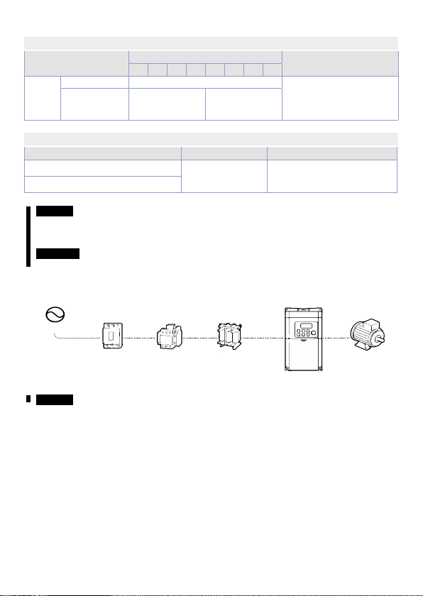
4.1 Basic configuration diagram .........................................................................................................9
4.2 Peripheral devices ...........................................................................................................................10
4.2.a Compatible circuit breaker, leakage breaker, magnetic contactor and motor
circuit breaker.....................................................................................................................10
4.2.b Fuse and reactor specifications...................................................................................10
4.2.c Braking resistor specification.......................................................................................10
4.3 Power terminal labels and descriptions .................................................................................11
4.4 Control terminal labels and descriptions...............................................................................12
4.4.a Control board switches...................................................................................................12
4.4.b Connectors...........................................................................................................................12
4.4.c Input terminal labels and descriptions ....................................................................12
4.4.d Output / Communication terminal labels and descriptions............................13
4.5 Disabling the EMC Filter for power sources with asymmetrical grounding............13
5 Learning to perform basic operations..........................................................................................................14
5.1 Operation keys..................................................................................................................................14
5.2 Control menu.....................................................................................................................................14
5.3 Table of functions in operation group ....................................................................................15
6 Technical Specification .......................................................................................................................................16
6.1 Input and output specification ..................................................................................................16
6.2 External dimensions .......................................................................................................................17
6.2.a 0.4~2.2kW (single phase) ...............................................................................................17

4 - PDR100 - User manual
1 Safety guidelines
Read carefully the safety guidelines and programming instructions contained in this
manual before connecting/using the device. Disconnect power supply before proceeding
to hardware settings or electrical wirings to avoid risk of electric shock, fire, malfunction.
Do not install/operate the device in environments with flammable/explosive gases.
This device has been designed and conceived for industrial environments and applications
that rely on proper safety conditions in accordance with national and international
regulations on labour and personal safety. Any application that might lead to serious
physical dama ge/ life risk or involve medical life support devices should be avoided.
Device is not conceived for applications related to nuclear power plants, weapon systems,
flight control, mass transportation systems.
Only qualified personnel should be allowed to use device and/or service it and only in
accordance to technical data listed in this manual. Do not dismantle/modify/repair any
internal component. Device must be installed and can operate only within the allowed
environmental conditions. Overheating may lead to risk of fire and can shorten the
lifecycle of electronic components.
1.1 Environmental policy / WEEE
Do not dispose electric tools together with household waste material. According to
European Directive 2002/96EC on waste electrical and electronic equipment and its
implementation in accordance with national law, electric tools that have reached the end
of their life must be collected separately and returned to an environmentally compatible
recycling facility.
2 Installation guidelines
• These devices are not ready for use upon delivery and must be installed and wired
according to the specifications in this documentation in order for the EMC limit values
to apply.
•
Installation must be performed according to this documentation using suitable
equipment and tools.
• Devices are only permitted to be installed by qualified personnel without voltage
applied. Before installation, voltage to the control cabinet must be switched off and
prevented from being switched on again.
• General safety guidelines and national accident prevention regulations must be
observed.
• Electrical installation must be carried out in accordance with applicable guidelines (e.g.
line cross sections, fuses, protective ground connections).
2.1 Organization of safety notices
Safety notices in this manual are organized as follows:
Safety notice Description
Danger! Indicates an imminently hazardous situation which, if not avoided,
will result in severe injury or death.
Warning! Indicates a potentially hazardous situation which, if not avoided,
could result in injury or death.
Caution!
Attention!
Indicates a potentially hazardous situation that, if not avoided, could
result in minor injury or property damage.

User manual - PDR100 - 5
2.2 Safety information
Danger!
• Do not open the cover of the equipment while it is on or operating. Likewise, do not
operate the inverter while the cover is open. Exposure of high voltage terminals or
charging area to the external environment may result in an electric shock. Do not
remove any covers or touch the internal circuit boards (PCBs) or electrical contacts on
the product when the power is on or during operation. Doing so may result in serious
injury, death, or serious property damage.
• Do not open the cover of the equipment even when the power supply to the inverter
has been turned off unless it is necessary for maintenance or regular inspection.
Opening the cover may result in an electric shock even when the power supply is off.
• The equipment may hold charge long after the power supply has been turned off. Use
a multi-meter to make sure that there is no voltage before working on the inverter,
motor or motor cable.
Warning!
• This equipment must be grounded for safe and proper operation.
• Do not supply power to a faulty inverter. If you find that the inverter is faulty, disconnect
the power supply and have the inverter professionally repaired.
• The inverter becomes hot during operation. Avoid touching the inverter until it has
cooled to avoid burns.
• Do not allow foreign objects, such as screws, metal chips, debris, water, or oil to get
inside the inverter. Allowing foreign objects inside the inverter may cause the inverter
to malfunction or result in a fire.
• Do not operate the inverter with wet hands. Doing so may result in electric shock.
• Check the protection degree of circuits and equipments used in the inverter degree of
circuit protection and the degree of equipment protection. The following connection
terminals and components are electrical protection class 0 devices. The circuit is
protected by the essential insulation and electric shock may occur if the insulation
is done improperly. The same protection measures for electric cables must be taken
when the using or installing the following compornents, or when you connect a cable
to the following terminals or components.
- Multi-function terminals: P1–P3, P4, P5, CM
- Analog terminal inputs and outputs: VR, V1, I2, AO, CM
- Other terminal block connectors: 24, A1, B1, C1, A2, C2
- Cooling fan
• This inverter is a protection class 1 product.
Caution!
• Do not modify the interior workings of the inverter. Doing so will void the warranty.
• The inverter is designed for 3-phase motor operation. Do not use the inverter to
operate a single phase motor.
• Do not place heavy objects on top of electric cables. Doing so may damage the cable
and result in an electric shock.

6 - PDR100 - User manual
3 Preparing the installation
3.1 Product identification
PDR100-1PH-(...) 0040 0075 0150 0220
Motor capacity 0.4kW 0.75kW 1.5kW 2.2kW
Input voltage Single phase 200V ~ 240V
Keypad LED Keypad
UL Type UL Open Type
EMC Filter Built-in EMC Filter(C2)
Reactor Non-Reactor
I/O 5 DI (NPN / PNP), 3 AI (1 potentiometer, 1 voltage, 1 voltage / current),
1 AO (voltage), 2 relays (1 nc / no, 1 no), RS485 Modbus-RTU
3.2 Installation considerations
Items Description
Ambient temperature* -10..50°C (14..122°F)
Ambient humidity 95% relative humidity (no condensation)
Storage temperature -20..65°C (-4..149°F)
Environmental factors An environment free from corrosive or flammable gases, oil
residue or dust
Altitude / vibration Lower than 1000m (3,280 ft) above sea level/less than 1G (9.8
m/sec)
Air pressure 70~106 kPa
* The ambient temperature is the temperature measured at a point 5 cm (2”) from the surface of the inverter.
Caution! Do not allow the ambient temperature to exceed the allowable range while
operating the inverter.
3.3 Selecting and preparing a site for installation
• The inverter must be installed on a wall that can support the inverter’s weight.
• The location must be free from vibration. Vibration can adversely affect the operation
of the inverter.
• The inverter can become very hot during operation. Install the inverter on a surface
that is fire-resistant or flame-retardant and with sufficient clearance around the
inverter to allow air to circulate. The illustrations below detail the required installation
clearances.
• Ensure sufficient air circulation is provided around the inverter when it is installed. If the
inverter is to be installed inside a panel, enclosure, or cabinet rack, carefully consider
the position of the inverter’s cooling fan and the ventilation louver. The cooling fan
must be positioned to efficiently transfer the heat generated by the operation of the
inverter.
• If you are installing multiple inverters in one location, arrange them side by side and
remove their top covers (optional). The top covers MUST be removed for side-by-side
installations. Use a flat head screwdriver to remove the top covers.
• If you are installing multiple inverters, of different ratings, provide sufficient clearance
to meet the clearance specifications of the larger inverter.
Note: the quantity and dimensions of the mounting brackets vary based on frame size.

User manual - PDR100 - 7
Caution!
• Do not transport the inverter by lifting with the inverter’s covers or plastic surfaces. The
inverter may tip over if covers break, causing injuries or damage to the product. Always
support the inverter using the metal frames when moving it.
• Use an appropriate transport method that is suitable for the weight.
• Do not install the inverter on the floor or mount it sideways against a wall. The
inverter MUST be installed vertically, on a wall or inside a panel, with its rear flat on the
mounting surface.
3.4 Cable selection and cable wiring
Load(kW)
Ground Power I/O
mmAWG mmAWG
R /T U/V/W R /T U/V/W
Single
Phase 200V
0.4, 0.75 3.5 12 2214 14
1.5, 2.2 3.5 12 3.5 3.5 12 12
Note: Class 3 grounding is required. Resistance to ground must be < 100Ω.
Warning! Install ground connections for the inverter and the motor by following the
correct specifications to ensure safe and accurate operation. Using the inverter and
the motor without the specified grounding connections may result in electric shock.
Caution!
• Tighten terminal screws to their specified torque. Loose terminal screws may allow
the cables to disconnect and cause short circuit or inverter failure. Over tightening
terminal screws may damage the terminals and cause short circuits and malfunctions.
• Use copper cables rated for 600V, 75°C for power terminal wiring.
• Use copper cables rated for 300V, 75°C for control terminal wiring.
• When making wiring connections at the power terminals, do not make a bi-wired
connection to a single terminal.
• Power supply cables must be connected to the R and T terminals. Connecting power
cables to the U, V, and W terminals will cause internal damage to the inverter. Connect
motors to the U, V, and W terminals. Phase sequence arrangement is not necessary.
Attention!
• Appliquer des couples de marche aux vis des bornes. Des vis desserrées peuvent provoquer
des courts-circuits et des dysfonctionnements. Ne pas trop serrer la vis, car cela risqué
d’endommager les bornes et de provoquer des courts-circuits et des dysfonctionnements.
Utiliser uniquement des fils de cuivre avec une valeur nominale de 600 V, 75°C pour le
câblage de la borne d’alimentation, et une valeur nominale de 300 V, 75°C pour le câblage
de la borne de commande.
• Ne jamais connecter deux câbles à une borne lors du câblage de l’alimentation.
• Les câblages de l’alimentation électrique doivent être connectés aux bornes R, T. Leur
connexion aux bornes U, V et W provoque des dommages internes à l’onduleur. Le moteur
doit être raccordé aux bornes U, V et W. L’arrangement de l’ordre de phase n’est pas
nécessaire.

8 - PDR100 - User manual
3.4.a Signal (control) cable specifications
Terminal
Signal Cable
Without Crimp Terminal
Connectors (Bare wire)
With Crimp Terminal
Connectors (Bootlace Ferrule)
mmAWG mmAWG
P1~P5/CM/VR/V1/I2/AO 0.75 18 0.5 20
A1/B1/C1/A2/C2 1.0 17 1.5 15
Caution!
• Wherever possible use cables with the largest cross-sectional area for mains power
wiring, to ensure that voltage drop does not exceed 2%.
• Use copper cables rated for 600V, 75°C for power terminal wiring.
• Use copper cables rated for 300V, 75°C for control terminal wiring.
3.4.b Cable wiring
Install the ground connection as specified. Complete the cable connections by connecting
an appropriately rated cable to the terminals on the power and control terminal blocks.
Caution!
• Install the inverter before carrying out wiring connections.
• Ensure that no small metal debris, such as wire cut-offs, remain inside the inverter.
Metal debris in the inverter may cause inverter failure.
• Tighten terminal screws to their specified torque. Loose terminal block screws may
allow the cables to disconnect and cause short circuit or inverter failure.
• Do not place heavy objects on top of electric cables. Heavy objects may damage the
cable and result in electric shock.
• The inverter’s power is supplied by the supply grounding system. The TT, TN, IT, and
corner-grounded systems are not suitable for this inverter.
• The inverter may generate direct current to the inverter’s protective ground cable.
Only type B Residual Current Devices (RCD) or Residual Current Monitors (RCM) can be
installed.
• Use cables with the largest cross-sectional area, appropriate for power terminal wiring,
to ensure that voltage drop does not exceed 2%.
• Use copper cables rated at 600V, 75°C for power terminal wiring.
• Use copper cables rated at 300V, 75°C for control terminal wiring.
• Connect the control terminals separately from the power terminal wiring or high
potential circuit (200 V relay sequence circuit).
• Ensure that there are no control terminal shorts or improper wiring. Control terminal
shorts or improper wiring may damage the inverter or cause malfunction.
• Use a shielded cable while making wiring connections at the control terminal.
Unshielded cables may cause the inverter to malfunction due to interference. Use an
STP cable if ground connections must be installed.
• If you need to re-wire the terminals due to wiring-related faults, ensure that the
inverter keypad display is turned off and the charge lamp under the front cover is off
before working on wiring connections. The inverter may hold a high voltage electric
charge long after the power supply has been turned off.

User manual - PDR100 - 9
3.5 Terminal screw specification
3.5.a Input / Output terminal screw specification
Product(kW) Terminal screw Size Screw Torque (Kgf*cm/Nm)
ERTB1 B2 U V W
Single
phase
200V
0.4/0.75 M3 M3 ~M3.5
(2.1~5.0/0.2~0.5)
M4
(2.1~8.0/0.2~0.8)
1.5/2.2 M4 M3.5
3.5.b Control circuit terminal screw specification
Terminal Terminal Screw Size Screw Torque(Kgf*cm/Nm)
P1~P5/CM/VR/V1/I2/AO M2.6 4.0/0.4
A1/B1/C1/A2/C2
Caution! Apply rated torques to the terminal screws. Loose screws may cause short
circuits and malfunctions. Tightening the screw too much may damage the terminals
and cause short circuits and malfuctions.
Attention! Appliquer des couples de marche aux vis des bornes. Des vis desserrées peuvent
provoquer des courts-circuits et des dysfonctionnements.
4 Installing the inverter
4.1 Basic configuration diagram
Power source
Circuit breaker
OR
Motor circuit
breaker
Magnetic
contactor
(optional)
Input side Output side
AC reactor
(optional)
Motor
Caution!
• Figures in this manual are shown with covers or circuit breakers removed to show a
more detailed view of the installation arrangements. Install covers and circuit breakers
before operating the inverter. Operate the product according to the instructions in this
manual.
• Do not start or stop the inverter using a magnetic contactor, installed on the input
power supply.
• If the inverter is damaged and loses control, the machine may cause a dangerous
situation. Install an additional safety device such as an emergency brake to prevent
these situations.
• High levels of current draw during power-on can affect the system. Ensure that correctly
rated circuit breakers are installed to operate safely during power-on situations.
• Reactors can be installed to improve the power factor. Note: that reactors may be
installed within 30 ft (9.14 m) from the power source if the input power is 10 times over
the inverter’s power.

10 - PDR100 - User manual
4.2 Peripheral devices
4.2.a Compatible circuit breaker, leakage breaker, magnetic contactor and
motor circuit breaker
Inverter
capacity
Circuit Breaker Leakage Breaker Magnetic Contactor
Rating [A] Rating [A] Rating [A]
0.4kW 15 5 9
0.8kW -10 -
1.5kW -15 18
2.2kW 20 20 22
4.2.b Fuse and reactor specifications
Inverter capacity AC Input Fuse AC Reactor
Current [A] Voltage[V] Inductance[mH] Current [A]
0.4/0.8kW 10
600
1.2 10
1.5kW 15 0.88 14
2.2kW 20 0.56 20
Caution! Use Class H or RK5 UL listed input fuse and UL listed breaker only. See the
table above for the voltage and current rating of the fuse and the breaker.
Attention!
Utiliser UNIQUEMENT des fusibles d’entrée homologués de Classe H ou RK5 UL et des
disjoncteurs UL. Se reporter au tableau ci-dessus pour la tension et le courant nominal des
fusibless et des disjoncteurs.
4.2.c Braking resistor specification
Product (kW) Resistance (Ω) Rated capacity (W)
1.5 60 300
2.2 50 400
The standard for braking torque is 150% and the working rate (%ED) is 5%. If the working
rate is 10%, the rated capacity for braking resistance must be calculated at twice the
standard.

User manual - PDR100 - 11
4.3 Power terminal labels and descriptions
Terminal Labels Name Description
R/T AC power input terminal Mains supply AC power connections.
B1/B2(1.5kW~2.2kW) Brake resistor terminals Brake resistor wiring connection.
U/V/W Motor output terminals 3-phase induction motor wiring
connections.
Note:
• Use STP (Shielded Twisted Pair) cables to connect a remotely located motor with the
inverter. Do not use 3 core cables.
• Ensure that the total cable length does not exceed 165ft (50m).
• Long cable runs can cause reduced motor torque in low frequency applications due to
voltage drop. Long cable runs also increase a circuit’s susceptibility to stray capacitance
and may trigger over-current protection devices or result in malfunction of equipment
connected to the inverter.
• Voltage drop is calculated by using the following formula:
Voltage Drop (V) = [√3 X cable resistance (mΩ/m) X cable length (m) X current(A)] / 1000
• Use cables with the largest possible cross-sectional area to ensure that voltage drop is
minimized over long cable runs. Lowering the carrier frequency and installing a micro
surge filter may also help to reduce voltage drop.
Distance < 50 m (165 ft) < 100 m (330 ft) > 100 m (330 ft)
Allowed Carrier Frequency < 15 kHz < 5 kHz < 2.5 kHz
Warning! Do not connect power to the inverter until installation has been fully
completed and the inverter is ready to be operated. Doing so may result in electric
shock.
Caution!
• Power supply cables must be connected to the R and T terminals. Connecting power
cables to other terminals will damage the inverter.
• Use insulated ring lugs when connecting cables to R/T and U/V/W terminals.
• The inverter’s power terminal connections can cause harmonics that may interfere
with other communication devices located near to the inverter. To reduce interference
the installation of noise filters or line filters may be required.
• To avoid circuit interruption or damaging connected equipment, do not install pha-
se-advanced condensers, surge protection, or electronic noise filters on the output
side of the inverter.
• To avoid circuit interruption or damaging connected equipment, do not install
magnetic contactors on the output side of the inverter.

12 - PDR100 - User manual
4.4 Control terminal labels and descriptions
4.4.a Control board switches
Switch Description
SW1 NPN/PNP mode selection switch
SW2 Analog voltage/current input terminal (I2) selection switch
SW3 Terminating resistor selection switch
4.4.b Connectors
Connector Description
RJ45 Port Connection of the remote keypad, Smart Copier, or RS 485
communication
4.4.c Input terminal labels and descriptions
Function Label Name Description
Multi-fun-
ction
terminal
configu-
ration
P1–P5
Multi-fun-
ction Input
1–5
Configurable for multi-function input terminals.
Factory default terminals and setup are as
follows:
- P1: Fx
- P2: Rx
- P3: Emergency stop trip
- P4: Fault reset (RESET)
- P5: Jog operation command (JOG)
CM Common
Sequence
Common terminal for analog terminal inputs
and outputs.
Analog
input con-
figuration
VR
Potentiome-
ter frequency
reference
input
Used to setup or modify a frequency reference
via analog voltage or current input.
- Maximum Voltage Output: 12V
- Maximum Current Output: 100mA,
- Potentiometer: 1–5kΩ
V1
Voltage input
for frequency
reference
input
Used to setup or modify a frequency reference
via analog voltage input terminal.
- Unipolar: 0–10V (12V Max.)
I2
Voltage/
current input
for frequency
reference
input
Used to setup or modify a frequency reference
via analog voltage or current input terminals.
Switch between voltage (V2) and current (I2)
modes using a control board switch (SW2).
V Mode:
- Unipolar: 0–10 V (12 V Max.)
I Mode:
- Input current : 4–20 mA

User manual - PDR100 - 13
4.4.d Output / Communication terminal labels and descriptions
Function Label Name Description
Analog
output AO Voltage
Output
Used to send inverter output information to
external devices: output frequency, output
current, output voltage, or a DC voltage.
- Output voltage: 0–10 V
- Max. output voltage/current: 10 V, 10 mA
- Factory default output: output frequency
Digital
output 24 External 24 V
power source Maximum output current: 50 mA
A1/C1/B1 Fault signal
output
Sends out alarm signals when the inverter’s
safety features are activated (AC 250V <1A, DC
30V < 1A).
- Fault condition: A1 and C1 contacts are
connected (B1 and C1 open connection)
- Normal operation: B1 and C1 contacts are
connected (A1 and C1 open connection)
A2/C2 Fault signal
output
Sends out alarm signals when the inverter’s
safety features are activated (AC 250V <1A, DC
30V < 1A).
- Fault condition: A2 and C2 contacts are
connected
- Normal operation: A2 and C2 contacts are
open connection
Commu-
nication RJ45
Remote
keypad signal
line
Used to send or receive the remote keypad
(optional) signals.
RS-485 signal
line
Used to send or receive RS485 signals on
Modbus-RTU protocol.
4.5 Disabling the EMC Filter for power sources with
asymmetrical grounding
Before using the inverter, confirm the power supply’s grounding system. Disable the EMC
filter if the power source has an asymmetrical grounding connection. Check the location
of the EMC filter on/off screw and attach the plastic washer to the screw under the control
terminal block.
STEEL BOLT STEEL BOLT + PLASTIC WASHER
EMC
EMC
CHARGE
MOTOR
+
+
EMC ON EMC OFF

14 - PDR100 - User manual
5 Learning to perform basic operations
5.1 Operation keys
The following table lists the names and functioins of the keypad’s operation keys.
Key Description
RUN
Starts the inverter.
STOP
RESET
STOP: stops the inverter.
RESET: resets the inverter following fault or failure conditions.
Switch between codes, or to increase or decrease parameter values.
MODE
SHIFT
Switch between groups, or to move the cursor during parameter setup
or modification.
ENT
Used to enter the parameter setting mode, apply the set parameter, and
enter the operation information screen from the fault notice screen when
a fault occurs.
MIN MAX
Used to set the operation frequency.
5.2 Control menu
The PDR100 inverter control menu uses the following groups.
Group Display Description
Operation -Configures basic parameters for inverter operation.
Drive dr Configures parameters for basic operations. These include
jog operation, torque boost, and other parameters.
Basic ba Configures basic parameters, including motor-related
parameters and multi-step frequencies.
Advanced ad Configure acceleration or deceleration patterns and to
setup frequency limits.
Control cn Configures functions such as carrier frequency or speed
search.
Input Terminal in Configures input terminal–related features, including
digital multi–functional inputs and analog inputs.
Output Terminal ou Configures output terminal–related features such as relays
and analog outputs.
Communication cm Configures communication features for RS-485 or other
communication options.
Application ap Configures PID control–related sequences and operations.
Protection pr Configures motor or inverter protection features.
Secondary motor
(2nd motor) m2
Configures secondary motor related features.
Note: the secondary motor (M2) group appears on the
keypad only when one of the multi-function input terminals
(In65-69) has been set to 12 (Secondary motor).
Configuration cf Configures various features such as parameter setting.

User manual - PDR100 - 15
5.3 Table of functions in operation group
Groups, except the Operation group, are not displayed on the group list and not accessible
as factory default to prevent parameter input error. To display and access all groups, go to
the OGr code in the Operation group and set the parameter to 1.
Display Comm.
Address Name Setting range Initial
Value Property*
0.00 0h1F00 Command
frequency 0.00 - Max. frequency [Hz] 0.00 O
ACC 0h1F01 Acceleration
time 0.0 - 6000.0 [s]
5.0 O
dEC 0h1F02 Deceleration
time 10.0 O
drv 0h1F03 Command
source
0Keypad 1 X
1Fx/Rx-1
2Fx/Rx-2
3RS-485 communication
Frq 0h1F04 Frequency
Setting method
0 Keypad 1 0 X
1 Keypad 2
2 V0: 0–5 [V]
3 V1: 0-10 [V]
4 I2( I ): 0-20 [mA]
5 I2(V): 0-10 [V]
6 V0 + I2 ( I )
7 V0 + I2 (V)
8 V0 + V1
9RS-485 communication
10 Up-down operation
MkW 0h1F05 Motor selection
0.1 - 0.1kW 0.2 – 0.2kW - X
0.4– 0.4kW 0.75 – 0.75kW
1.5 – 1.5kW 2.2 – 2.2kW
MrC0h1F06 Rated motor
current 0.1 ~ 150.0[A] - X
MbF 0h1F07 Base frequency 30.00 ~ 400.00[Hz] 60.00 X
FrM 0h1F08 Maximum
frequency 40.00 ~ 400.00[Hz] 60.00 X
IOv 0h1F09 Output voltage
setting 0, 170~264[ V] 0 X
Ftb 0h1F0A Forward boost 0.0~20.0[%] 4.0 X
rtb 0h1F0B Reverse boost 0.0~20.0[%] 4.0 X
CUr 0h1F0C Output current - - -

16 - PDR100 - User manual
Display Comm.
Address Name Setting range Initial
Value Property*
rPM 0h1F0D Motor
RPM - - -
dCL 0h1F0E Inverter
DC voltage - - -
vOL, POr,
tOr, v1M,
I2M
0h1F0F User select
signal
vOL Output voltage vOL -
POr Output power
tOr Output torque
v1M Analog V1 terminal input
I2M Analog I2 terminal input
nOn 0h1F10 Currently out of
order - - -
OGr 0h1F11 Open hidden
groups
0Hide groups except for
operation group
1Enable all groups
1 The setting range varies depending on the set value of the bA 8 code.
2 The initial value varies depending on the motor capacity setting (MkW) and the value is set based on the
220/440 HIGEN motor when shipping.
3 Display information can be selected at dr81 (Monitor item setting).
* Settings can be changed during the inverter operation.
6 Technical Specification
6.1 Input and output specification
PDR100-1PH-xxxx-2- 0040 0075 0150 0220
Applied
motor Heavy load HP 0.5 1.0 2.0 3.0
kW 0.4 0.75 1.5 2.2
Rated output
Rated capacity
(kVA) 0.95 1.9 3.0 4.5
Rated current (A) 2.4 4.2 7. 5 10.0
Output frequency 0~400Hz
Output voltage (V) 3-phase 200~240V
Rated input
Working voltage (V) Single phase 200~240Vac (-15%~+10%)
Input frequency 50~60Hz(±5%)
Rated current (A) 3.7 7.1 13.6 18.7
Weight (kg/lb) 1 / 2.2 1.45 / 3.2

User manual - PDR100 - 17
6.2 External dimensions
6.2.a 0.4~2.2kW (single phase)
W1
D1
H1
A
Ø
H4
H2
H3
W2
B
Items* W1 W2 H1 H2 H3 H4 D1 A B Φ
PDR100-1PH-040
PDR100-1PH-075
85
(3.34)
75
(2.95)
153
(6.02)
153.5
(6.04)
163
(6.42)
5
(0.19)
123
(4.84)
5
(0.19)
4.5
(0.18)
4.5
(0.18)
PDR100-1PH-0150
PDR100-1PH-0220
100
(3.94)
90
(3.54)
180
(7.08)
180.5
(7.10)
190
(7.48)
5
(0.19)
140
(5.51)
5
(0.19)
4.5
(0.18)
4.5
(0.18)
* Unit: mm (inches)
Note / Updates

18 - PDR100 - User manual


PIXSYS s.r.l.
www.pixsys.net
online assistance: http://forum.pixsys.net
2300.10.280-RevB
010419
Read carefully the safety guidelines and programming instructions
contained in this manual before using/connecting the device.
Other manuals for PDR100
1
Table of contents
Other Pixsys Inverter manuals