Eguana Evolve LFP AU - 14 kWh Installation manual

Model
Evolve LFP AU – 14 kWh
Evolve LFP AU – 28 kWh
Evolve LFP AU – 42 kWh
Grid Support Utility Interactive Inverter
& Integrated Lithium Battery
For use only with battery model
•Pylontech US3000C
Installation & Start-up Guide

Revision History
Revision
Date
Status
Author
Comments
1.0
09.Jan.2023
Draft
RWM
Initial release.

IMPORTANT SAFETY INSTRUCTIONS
SAVE THESE INSTRUCTIONS
This manual ontains important instru tions for the Evolve™ Home Energy Storage System – in luding the
power ontrol system (PCS) and base model battery abinet installation and operation. This produ t is
expandable with the addition of up to two more battery abinets. The Eguana Evolve™ omponents des ribed
by this manual are intended to be used as part of an Energy Storage system and installed as per the lo al
ele tri al ode.
CAUTION: Hazardous Voltages! This inverter ontains hazardous voltage and energy that may be
lethal. It may only be installed by qualified personnel who have read this manual and are familiar with
its operation and hazards. The following safety pro edures should be followed:
Only onne t the PCS abinet to a ompatible ele tri al servi e as defined in the model spe ifi ations. The PCS
must be onne ted to a dedi ated bran h ir uit in the main ele tri al panel.
An external dis onne t swit h shall be provided in the end installation by others for the AC Grid output ir uit.
CAUTION! This equipment ontains high energy lithium batteries. Qualified and trained personnel should wear
prote tive lothing and equipment when working inside the battery abinet and/or with battery
modules.
The PCS is ompatible with the Pylonte h US3000C battery only.
CAUTION! The batteries provided with this system must be harged only by the PCS in luded as part of the
energy storage system. Do not attempt to harge batteries with any other harger devi e or onne t
any devi es dire tly to the DC battery bus.
Ensure proper ele tri al grounding in a ordan e with ode requirements.
Ensure proper airflow path for a tive ooling.
Never operate system in a manner not des ribed by this manual.
Only qualified personnel should servi e this produ t.
Ensure all overs are se urely fastened after installation is omplete.
This produ t must be stored indoors in an environmentally onditioned lo ation prior to installation, prote ted
from rain and exposure to any hazardous hemi als.
Do not attempt to operate this produ t if there is any physi al eviden e of damage to any of the abinets or
internal omponents.
CAUTION! This equipment is heavy. Me hani al lifts are re ommended for safe installation.

Contents
1 SAFETY....................................................................................................................................................................... 1
1.1
I
N CASE OF EMERGENCY
..................................................................................................................... 1
1.2
B
ATTERY MODULE SAFETY PRECAUTIONS
............................................................................................ 1
1.3
G
ENERAL SAFETY PRECAUTIONS
........................................................................................................ 2
1.4
E
NVIRONMENTAL
P
ROTECTION
-
D
ISPOSAL AND
R
ECYCLING
................................................................. 2
2 INTRODUCTION ...................................................................................................................................................... 3
2.1
A
BOUT THIS
M
ANUAL
–
T
ARGET
A
UDIENCE
......................................................................................... 3
2.2
G
LOSSARY
........................................................................................................................................ 3
2.3
I
NITIAL
I
NSPECTION OF
M
ATERIAL
L
IST
................................................................................................ 4
2.3.1 LFP AU install kit – mechanical parts and manuals ............................................................................... 5
2.3.2 Install kit – battery cables .............................................................................................................................. 6
2.4
S
PECIAL
T
OOLS
&
H
ARDWARE
........................................................................................................... 7
2.5
I
NVERTER
/DSP
F
IRMWARE
V
ERSION
.................................................................................................. 7
3 INSTA ATION SITE PREPARATION ............................................................................................................... 8
3.1
L
OCATING THE SYSTEM
...................................................................................................................... 8
3.2
I
NSTALLATION
A
REA
R
EQUIRED TO
W
ALL
M
OUNT
PCS
AND
B
ATTERY
:................................................. 8
3.3
I
NSTALLATION PLAN
–
POWER AND COMMUNICATION CIRCUITS
.............................................................. 9
3.4
SLD
-
AC
C
OUPLED
PV
S
YSTEM WITH
B
ACK
-
UP
P
OWER
O
PERATION
................................................ 10
4 PCS AND BATTERY CABINET WA -MOUNTING INSTRUCTIONS ..................................................... 11
5 BATTERY MODU E ASSEMB Y ........................................................................................................................ 13
5.1
B
ATTERY CABINET GROUND BUS
....................................................................................................... 13
5.2
DC
NEGATIVE POWER TERMINAL ASSEMBLY
...................................................................................... 13
5.3
P
REPARING BATTERY MODULES FOR INSTALLATION
........................................................................... 14
5.4
M
OUNTING AND GROUNDING THE BATTERY MODULES IN THE BATTERY CABINET
................................... 15
5.5
W
IRING THE BATTERY MODULES
....................................................................................................... 16
5.5.1 attery module DC -/+ jumper cable wiring ......................................................................................... 16
5.5.2 MS communication jumper cable wiring ............................................................................................. 16
5.5.3 PCS to MS communication cable .......................................................................................................... 17
5.6
DC-
BATTERY MODULE TO CABINET
DC-
CONNECTIONS
..................................................................... 18
5.7
PCS
DC+
POWER AND BREAKER ASSEMBLY WIRING
.......................................................................... 19
6 SYSTEM E ECTRICA WIRING ......................................................................................................................... 20
6.1
AC
POWER CONNECTIONS
................................................................................................................ 20
6.2
C
HASSIS
G
ROUNDING
...................................................................................................................... 22
7 ENERGY METER INSTA ATION ..................................................................................................................... 22
7.1
E
LECTRICAL CONNECTIONS
–
VOLTAGE MEASUREMENT
/
POWER SUPPLY
............................................ 22
7.2
CT
(
CURRENT TRANSFORMER
)
CONNECTIONS
................................................................................... 22
7.3
RS-485
COMMUNICATION CONNECTION
............................................................................................ 23
8 DROP ET ETHERNET CONNECTION TO HOME ROUTER ....................................................................... 23
8.1
E
THERNET CABLE CONNECTION
........................................................................................................ 23
9 DRED DEVICE CONNECTION ............................................................................................................................ 23
10 BATTERY MODU E BMS DEFINITIONS AND OPERATING STATES ................................................. 24
11 START-UP SEQUENCE ...................................................................................................................................... 25
11.1
S
HUTDOWN
S
EQUENCE
.................................................................................................................. 25
12 OPERATION ......................................................................................................................................................... 26
12.1
U
PDATING THE
PCS
FACTORY REGIONAL SETTINGS
......................................................................... 26

13 PCS DISP AY PANE ........................................................................................................................................ 26
13.1
LED
D
ISPLAY
I
NDICATORS
............................................................................................................. 26
13.2
PCS
DISPLAY PANEL INDICATOR SUMMARY
. .................................................................................... 26
13.3
S
ERVICE
B
UTTON
.......................................................................................................................... 27
13.4
B
ACKUP
P
OWER
O
PERATION
.......................................................................................................... 27
13.4.1 ackup Power Display Modes ................................................................................................................ 27
13.5
O
FF
-
GRID MODE
:
R
ESTARTING THE BATTERY SYSTEM AFTER LOW BATTERY SHUTDOWN
.................... 28
14 MAINTENANCE ................................................................................................................................................... 28
15 TROUB ESHOOTING ........................................................................................................................................ 29
16 SYSTEM DECOMMISSIONING PROCEDURE .............................................................................................. 29
16.1
S
ERVICEABLE
P
ARTS
–
B
ATTERY MODULE REMOVAL
/
REPLACEMENT
................................................. 29
17 TECHNICA DATA ............................................................................................................................................. 30
17.1
PCS
CABINET DATA
....................................................................................................................... 30
17.1.1 PCS Regional Settings – Factory Default ............................................................................................ 31
17.2
B
ATTERY CABINET DATA
................................................................................................................. 31
17.3
W
IRE AND TORQUE RATINGS
........................................................................................................... 31
17.4
T
HERMAL PERFORMANCE
:
C
HARGE
/
D
ISCHARGE
C
URVES
.............................................................. 32
APPENDIX A: BATTERY EXPANSION CABINET INSTA ATION – BATTERIES #5 TO #8 ................ 33
A.1
I
NITIAL
I
NSPECTION OF
M
ATERIAL
L
IST
–
TOP LEVEL SYSTEM COMPONENTS
....................................... 33
A.1.1 LFP AU battery expansion materials list. .............................................................................................. 33
A.1.2 Expansion install kit – mechanical parts ................................................................................................ 33
A.1.3 Expansion kit – battery cables .................................................................................................................. 34
A.2
W
ALL BRACKET INSTALLATION
.......................................................................................................... 35
A.3
M
OUNTING THE CABINET TO THE WALL
.............................................................................................. 35
A.4
B
ATTERY MODULE ASSEMBLY
........................................................................................................... 35
A.5
B
ATTERY MODULE WIRING
................................................................................................................ 35
APPENDIX B: E ECTRICA B OCK DIAGRAM – INTERNA ....................................................................... 36
APPENDIX C: ENERGY METER WIRING DIAGRAMS ..................................................................................... 37
C.1
E
ASTRON
SDM630MCT-40
M
A....................................................................................................... 37
1
1 Safety
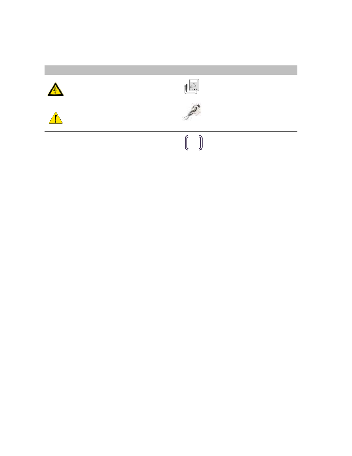
Throughout this manual, the following symbols will be used to highlight important information and pro edures:
Symbol
Definition
Symbol
Definition
WARNING! A dangerous voltage or
other condition exists. Use extreme
caution when performing these tasks.
Meter measurement required.
AUTION!
This information is critical to
the safe installation and or operation of
the inverter.
Follow these instructions closely.
Torque rating riti al to operation.
NOTE: This statement is important.
Follow instructions closely.
Login to the remote monitoring
system for operating status
1.1 In ase of emergen y
In all cases:
If safe to do so, swit h off the AC breakers (external to the system) for the system.
•
Conta t the fire department or other required emergen y response team.
•
Eva uate the area, and if appli able, follow your emergen y eva uation plan if others are in proximity to
the installed lo ation.
In case of fire:
•
When safe, use a fire extinguisher suitable for use; in luding A, B, and C dry hemi al fire extinguishers or
arbon dioxide extinguishers.
In case of flooding
:
•
Stay out of water if any part of the system or wiring is submerged.
•
Do not attempt to operate batteries that have been submerged in water even after they have been dried.
In case of unusual noise, smell or smoke:
•
If safe to do so, ventilate the area.
1.2 Battery module safety pre autions
This produ t is integrated with Pyltonte h US3000C series battery modules. Refer to the Pylonte h produ t
manual for omplete safety instru tions regarding handling of battery modules.
EMS

2
1.3 General safety pre autions
Important!
Installation, servi e, and operating personnel must read this do ument in its entirety, and
observe all safety and installation pro edures as des ribed in this manual. Never operate system in a
manner not des ribed by this manual.
Only qualified personnel should servi e this produ t.
Ensure all overs are se urely fastened after installation is omplete.
Personal Prote tive Equipment (PPE) in omplian e with lo al work pla e safety standards must be worn when
working inside the abinet.
Risks of Fire
Do not expose the system to temperatures ex eeding 60 degrees Celsius.
Avoid installation in dire t sunlight.
Do not store obje ts on top of the abinet.
Do not obstru t the intake or exhaust of the for ed airflow system.
Do not store ombustible obje ts and orrosive hemi als dire tly adja ent to the system.
Risks of Shock
WARNING! Hazardous Voltages. The Inverter contains hazardous voltage and energy that
may be lethal
. It may only be installed by qualified personnel who have read this manual and are
familiar with its operation and hazards.
Only onne t this produ t to a ompatible ele tri al servi e as defined in the model spe ifi ations.
This produ t must be onne ted to a dedi ated bran h ir uit in the main ele tri al panel.
Ensure proper ele tri al grounding in a ordan e with ode requirements.
CAUTION! Both AC and DC voltage sources are terminated inside this product. Each circuit
must be individually disconnected before servicing.
Risks of Damage
This system is compatible with the Pyltontech US3000C battery only.
Do not attempt to
onne t any other battery to the system.
Do not onne t any other loads, harge ontrollers, or PV panels dire tly to the DC battery sour e.
Do not drop, tip, or pun ture the abinet during transport and installation. Visible damage to the
abinet and/or internal omponents should be reported to the manufa turer immediately.
Do not store this system for periods longer than six months without a battery maintenan e harge.
This may result in permanent damage to the batteries.
1.4 Environmental Prote tion- Disposal and Re y ling
Do not dispose of the system or any of the omponents within the abinet. Batteries, ele troni s, ables,
and metal parts are re y lable. Consult your muni ipal waste management authority to determine
required methods of omponent re y ling.

3
2 Introduction
2.1 About this Manual – Target Audien e
This manual is intended to be used by qualified servi e and installation personnel for the purposes of produ t
installation. This produ t is permanently wired to the home ele tri al servi e, and must be installed by a li ensed
ele tri ian only. This manual ontains instru tions for the installation and start up sequen e of the Eguana Evolve™
home energy storage system; in luding the PCS and master battery abinets, the energy meter, and Ethernet
onne tion to a ustomer supplied internet router.
IMPORTANT! This manual makes frequent referen es to a utility intera tive solar PV system as part of an
AC oupled solar plus storage installation, whi h is independently supplied, installed, and operated from the
ESS. It is the responsibility of the installer to ensure that any utility intera tive PV system onne ted to a ba kup
panel for mi ro-grid operation is ompatible for use with a grid-forming battery inverter.
The energy management system supplied with this produ t an monitor the AC power output of an independently
installed utility intera tive solar PV inverter to operate energy savings algorithms appli able to the lo al ele tri al
utility; either via CT monitoring, or via ompatible ommuni ation proto ols with a sele t list of PV inverter models.
Consult Eguana Te hnologies for the most re ent list of PV inverters with dire t ommuni ation to the energy
management system.
This produ t an supply limited ba kup power, and ontains separate grid and load ports to isolate ba kup loads
during a grid outage. When this produ t is not in servi e, ba kup loads are routed dire tly to the grid panel via the
internal PCS bypass relay.
The AC output of an independently installed utility intera tive solar PV inverter an be wired to the ba kup panel to
support solar battery harging during ba kup operation.
The battery apa ity of this system an be expanded by adding additional abinets adja ent to the master battery
abinet. Expansion of battery apa ity is not overed within the s ope of this do ument.
2.2 Glossary
Term Definition Term Definition
AC Alternating Current GND Ground
ARC Auto Re overy Cir uit LED Light Emitting Diode
AS/NZS
Standards Australia NC Normally Closed
CEC Clean Energy Coun il NO Normally Open
CPU Central Pro essing Unit PCS Power Control System (Inverter)
DC Dire t Current PE Prote tive Earth
DRED Demand Response Enabling Devi e PV Photo-Voltai
DRM Demand Response Mode RF Radio Frequen y
EMS Energy Management System SOC State Of Charge (Battery)
ESD Ele trostati Dis harge SOH State of Health (Battery)
ESS Energy Storage System
4
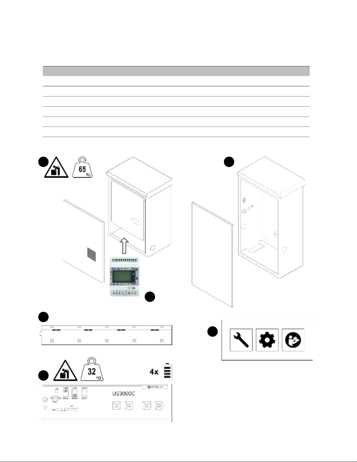
2.3 Initial Inspe tion of Material List
The system omponents supplied with the Eguana Evolve™
LFP AU are shown below. Ea h omponent should be
inspe ted visually for any damage that may have been aused by shipment. If damage is present, please onta t
your lo al distributor.
*The energy meter is supplied inside the PCS abinet, but an be relo ated to the ele tri al panel.
Item
Eguana P/N Description
1
ACB05-PE PCS abinet (and over)
2
ACB05-PB Battery Cabinet (and over)
3
- Wall mount bra ket
4
US3000C 4 battery modules.
5
LFP AU install kit Assembly parts kit, ables, CT’s, and manuals.
6
- Energy meter, 3 phase*
1
2
3
4
5
6
Figure
1
: Evolve LFP AU materials list.

5
2.3.1 LFP AU install kit – mechanical parts and manuals
Item Qty
Eguana P/N Description
Battery Cabinet
1
1 PB kit In l. abinet oupler assembly, two levelling bra kets, and two plugs
2
1
Breaker
Assembly DC breaker assembly
3
8 801003794 Adhesive ba ked battery module pads
4
1 801003757
Battery ra k partition bra ket (in ludes atta hed battery retaining lip
801003044)
PCS Cabinet
5
1 LP kit
In l. levelling bra ket, abinet oupler end plate, plug, and PCS
-
BMS
ommuni ation able.
The P S-BMS cable provided will match the battery type
supplied with the equipment.
6
3 - Energy Meter CT’s, 100A/40mA, split- ore
-
1 Do 82013 Evolve LFP Installation and Startup Manual
-
1 Do 58159 Evolve LFP System Owner’s Manual
5
LP kit
US3000C
PB kit
M4 x 25 mm
1
2
3
4
8x
Breaker
assembly
M5
x3 (3
Ø)
6
Figure
2
: LFP AU install kit materials list.

6
2.3.2 Install kit – battery cables
Item
Qty
Eguana P/N Description Pylon p/n
1
2 801003790 DC- module jumper BLK 180 mm WI0BSC1000B2
2
1 801003793 DC- module jumper BLK 400 mm WI0CUS300004
3
2 801003798 DC- terminal jumper BLK 400 mm WI0CUS300002
4
3 801003789 DC+ module jumper RED 180 mm WI0BSC100001
5
1 801003796 DC+ terminal jumper RED 400 mm WI0CUS300001
6
1 801003797 DC+ terminal jumper RED 700 mm WI0PUS300001
7
2 801003792 BMS jumper short 210 mm WI0SRJ458025
8
1 801003794 BMS jumper long 700 mm WI0SUS300002
9
4 801003791 Chassis GND able GRN/YEL 1 m WI0GUS300001
DC
-
DC +
BMS
GND
1
2
3
4
5
6
7
8
9
Figure
3
: attery cables materials list.

7
2.4 Spe ial Tools & Hardware
In addition to standard tools, the following tools and hardware should be readily available for the installation.
•Torque wren h
•17mm so ket wren h (battery negative main power onne tion).
•10mm so ket wren h (battery +/- module power onne tions).
•3/8” so ket wren h (battery positive main power onne tion).
•RJ-45 rimp tool (EMS to PCS ommuni ation able) and RJ-45 onne tors.
•M8 mounting hardware for wall bra ket (load bearing).
2.5 Inverter/DSP Firmware Version
The Inverter/DSP firmware version is displayed within the equipment devi e menu of the Swit hDin Smart Energy
appli ation, available both in IOS and Android. Open the appli ation, then pro eed to:
Unit >> Equipment (Devi es) >> EguanaPCS >> Information: PCS. Field = Inverter/DSP Firmware version.

8
3 Installation Site Preparation
Before installing the Evolve home energy storage omponents, read all instru tions and warnings in this manual.
AUTION! All electrical installation work should be performed in accordance with local building and
electrical codes.
WARNING! Isolate the PCS from all energy sources prior to electrical installation by means of disconnects,
breakers or connectors. Failure to properly isolate either AC or DC sources may result in serious injury or
death. This system will generate an AC voltage at the off-grid terminals when DC source is applied.
AUTION! The P S cabinet weighs up to 65 kg, and the battery cabinet weighs up to 145 kg. Handle
with care.
The wall must be load-bearing rated a ording to the lo al building ode. Me hani al lifts are
re ommended to position abinets on the wall bra ket.
3.1 Lo ating the system
1. The installation lo ation must omply with the environmental rating of the produ t. Refer to the
environmental ratings in se tion 17.2 of this manual.
CAUTION! Do not install in direct sunlight. attery performance is dependent upon operating ambient
temperature. Radiant heat absorbed in direct sunlight will greatly reduce the performance of the
battery, and will prematurely cause degradation of the display indicator panel on the P S cabinet. The battery
modules are rated for full power operation between -10C to +45C.
2. The for ed air ooling of the PCS abinet is from bottom to top. Refer to figure 1 for re ommended layout
plan.
3. All inter- abinet abling is limited in length. Separating abinets is not permitted.
4. Wall mounting hardware not in luded. The load-bearing wall bra ket is provisioned for M8 hardware.
Levelling bra kets are provisioned for M5 hardware.
3.2 Installation Area Required to Wall Mount PCS and Battery:
The physi al installation of the abinets requires the layout planning and installation of the system omponents in
the available installation spa e. The re ommended installation height is driven by the viewing angle of the display
panel on the PCS abinet.
Figure
4
: Installation clearances.

9
3.3 Installation plan – power and ommuni ation ir uits
The following example outlines the onduit plan for power and ommuni ation ir uits for the battery system. In
this example, the PV inverter is oupled to a ba kup power sub-panel. The sub-panel may also be an isolated power
bus within the main ele tri al panel.
NOTES:
1- The battery system is rated 5 kVA maximum. Solar self onsumption prevents battery power export,
however, the grid power ir uit must ele tri ally a ommodate the total of both battery and PV generation
when PV is onne ted to the ba kup ir uit.
2- The example above is shown with the energy meter relo ated from the PCS to the main ele tri al panel.
For installations where the energy meter is lo ated within the PCS, the CT ( urrent) and voltage sense
wiring must be routed from the utility side of the ele tri al panel to the energy meter inputs. Refer to
se tions 7 and Appendix C for more details.
Signal
Definition
Rating
P1
Grid power
-1
10 kVA max (5 kVA battery + 5 kVA PV), 230 Va ,
1
Ø
P2
Ba kup power
5 kVA max, 230 Va ,
1
Ø only
P3
PV power (AC), oupled to ba kup
5
kVA max, AC, 1
Ø only
P4
Home load ir uits
, ba kup power
16 A / 230 Va ,
1
Ø only
S1
Energy meter (RS
-
485)
-2
CAT
-
5, STP
S2
DRED devi e, Ethernet
CAT
-
5, UTP
S3
Home router, Ethernet
CAT
-
5, UTP
Figure
5
: Installation plan.

10
3.4 SLD - AC Coupled PV System with Ba k-up Power Operation
The single line diagram shown below is a representation of a typi al installation onfigured for utility intera tive and
ba k-up power operation, with AC oupled PV onne ted to a riti al load panel. This drawing is a guideline only,
and is not a substitute for a ode ompliant installation. All omponents required for a ode ompliant installation
are the responsibility of the li ensed installer, in luding any additional ir uit prote tion requirements not shown
here.
NOTES
1. The ba kup power bus must be ele tri ally isolated from the main ele tri al bus. Do not tap the neutral wires of the main
and ba kup buses. A separate line, neutral, and ground must be run to ea h of the load and grid ports of the battery
system. Refer to the installation manual for wiring details.
2. Energy meter supports 1Ø and 3Ø onfiguration. In the above ase, the energy meter was removed from the PCS abinet
and relo ated to the main panel.
3. 3Ø servi e shown. For 1Ø servi e, do not populate L2, L3 ph omponents.
4. The battery system must be earth bonded to the building ground to meet lightning prote tion requirements.
5. The battery system load and grid ports are independently ontrolled ir uits. Should the ele tri al ode require additional
“line-of-sight” dis onne ts, a separate dis onne t must be used for ea h of the grid and load ports. The dis onne ts
and/or ir uit breakers must operate independently of ea h other, and not be ganged.
6. The PCS provides galvani separation of AC and DC sour es. Over urrent prote tion devi es, RCD Type A (300 mA), are
suffi ient for prote tion of both AC Grid and AC load ports.
7. Total AC nameplate of PV not to ex eed 5 kW. String inverter shown for simpli ity. Multiple AC strings of mi ro-inverters
permitted. Any additional PV installed on the grid side of the battery system operates independently from the battery
system, and is only limited by the inter onne tion requirements of the utility servi e provider.
8. The maximum ondu tor size permitted for the PCS grid port is 16 mm
2
, and maximum breaker rating of 63 Amp to
prote t the internal ir uits of the PCS. The ESS breaker rating and ondu tor size an be redu ed, however, these
parameters are subje t to the total possible ontinuous output urrent of ombined PV and ESS generation at the ESS grid
breaker in the main ele tri al panel. Variables that determine ondu tor sizing in lude; PV ontinuous output urrent
rating onne ted to the ESS load terminal, total self-supply urrent to the main ele tri al panel (load onne ted PV plus
ESS output), and length of run from the ESS grid port to the main ele tri al panel (voltage drop). Condu tor sizing is the
responsibility of the installer as per the a tual installation, ompliant to lo al / national ele tri al odes. Refer to the
te hni al data in se tion 17.1 for Maximum AC fault urrent and duration (short ir uit).
9. The PCS short ir uit withstand apa ity is rated at 10 kA (1 se ond). Cir uit prote tion must not ex eed this rating.
*DRED: Australia only.
**
See note 8.
**
See
note 9
.
N L
3
L
2
L1
Main Bus3
M
Emergen y
swit hing devi e
Figure
6
:
Single Line Diagram: Typical AC coupled PV system.
11
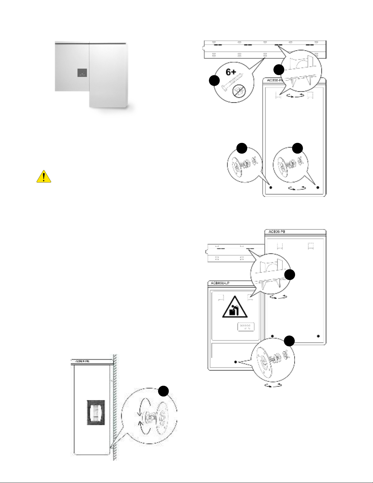
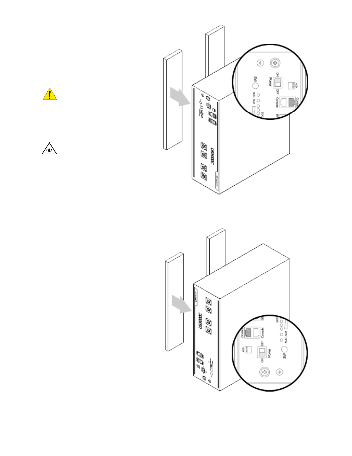
4 PCS and Battery Cabinet Wall-Mounting Instructions
1. Mount the wall bra ket to the wall. Use the available slot
pattern to mount to a load-bearing stru ture rated for the
weight of the final system. The slots a ommodate a M8
(5/16”) bolt diameter.
IMPORTANT!
Wall-stud mounting: A minimum of
three wall studs spanned within the width of the
mounting bra ket are required. A minimum of two
mounting bolts are required per stud (top/bottom).
2. (not shown) Remove the battery abinet from the
pa kaging, and stand the abinet upright. Remove the
front over.
3. Mount the two leveling bra kets to the ba k side of the
abinet. Ea h side of the abinet must have a rubber
washer in dire t onta t with the abinet wall.
4. Lift the battery abinet onto the wall mount bra ket,
aligning the wall hooks at the rear of the abinet with the
slots on the load-bearing fa e of the bra ket.
5. Slide the battery abinet towards the right end of the
bra ket to allow for learan e for the PCS abinet.
6. From the rear side of the abinet, adjust the outer wingnuts
on the levelling bra kets until the abinet is verti ally plumb
(level) to the wall.
1
3
4
3
9
8
6
Figure
7
: Installation
instructions.
12
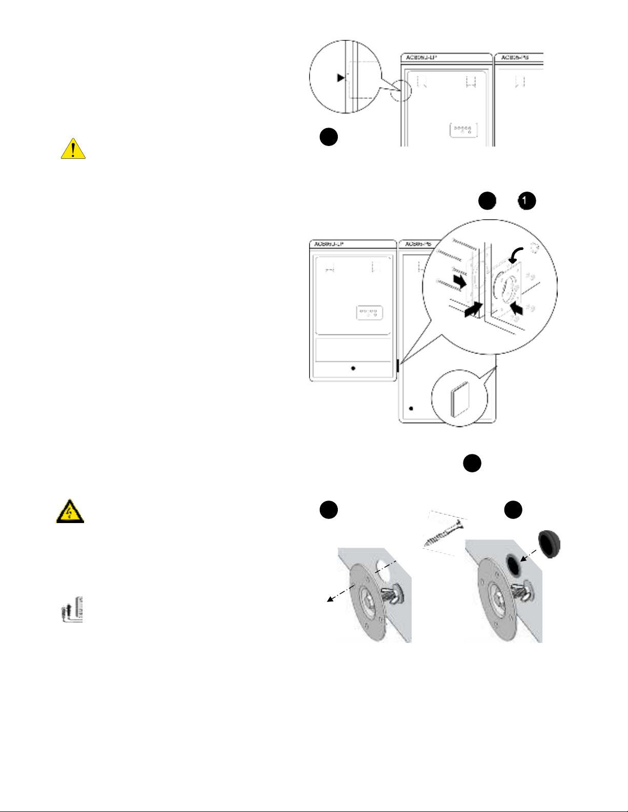
7. Remove the PCS abinet from its pa kaging and
stand upright. (not shown). Remove the front
over.
8. Assemble and mount the single lower- enter
leveling bra ket as shown in steps 3 and 4 above.
CAUTION!
The PCS abinet is heavy.
Me hani al lift or two persons re ommended.
9. Lift the PCS abinet onto the wall mounting bra ket.
10. Slide the PCS abinet to the left su h that it aligns
with the alignment tab on the mounting bra ket.
11. From the rear side of the abinet, adjust the outer
wingnut on the single levelling bra ket until the
abinet is verti ally plumb (level) to the wall. (see
image – step 6).
12. Insert the PCS abinet oupling gasket between the
two abinets (lower-front). Slide the battery abinet
towards the left until mating to the gasket.
13. Pla e the oupling plate inside the PCS abinet and
insert the four mounting bolts and washers through
to the battery abinet side.
14. Pla e star washers on the bolts on the battery side
of the abinet.
15. Mount the battery abinet side oupling plate, and
fasten with the lo k nuts. Torque to 10 – 15 in-lbs.
WARNING! The mounting bolts of the flange
assembly are required to be fully secured, as
they provide the chassis grounding for the
battery cabinet. Torque nuts as specified in the
specification tables provided in this manual.
16.
Continuity test:
Che k the ontinuity
between the abinets using an Ohm meter. The
test reading must be zero Ohms at a bare metal
point inside ea h of the PCS and battery abinets.
17. Install the abinet oupler end plate (see- LP kit) to
seal the hole on the battery abinet.
18. Optional: (This is not a load bearing an hor –
an hored onduit runs to the PCS are satisfa tory). Install s rews in leveling plates for PCS and battery abinets
by inserting a s rewdriver through the hole on the ba kside of the abinets.
19. Plug hole on ba k of abinet using by inserting the hole plug from the front side.
10
Optional (
hardware
not in luded)
12
16
thru
18
19
X4
17
Figure
8
: Installation
instructions.

13
5 Battery Module Assembly
The following instru tions in lude:
•Preparation and assembly of the battery abinet
modules and internal wiring.
•Inter onne tion of the PCS DC and ommuni ation
ables to the battery abinet.
Note: Overcurrent protection of the DC source is
provided internally as part of the integrated battery
system. No external DC disconnect is required.
5.1 Battery abinet ground bus
CAUTION!
A torque wrench is required to
ensure the power cables are terminated to their
specifications.
Over-torque an damage the DC
breaker and/or strip the threads on the opper bus bar
posts. Under-torque an result in an ar fault hazard, and
risk of fire. Damage as a result of improper termination is
not overed by the manufa turer warranty.
1. Mount the four ground wires provided in the battery
module grounding kit into the 4-position ground
distribution blo k.
5.2 DC negative power terminal assembly
2. Route the DC negative power able from the PCS
through the abinet port and mount to the DC
negative power terminal.
3. Mount the two DC negative battery module power
ables, referen ed A3, (as provided in the battery
able kit) to the DC negative power terminal. Offset
ea h power lug so that a flush ele tri al onta t is made between ea h of the lugs.
4. Se ure the DC negative power ables to the power terminal using the washer, lo k washer, and
hex nut provided. Torque the nut to 35 in/lbs.
Ref
P/N
Description
Pylon p/n label
A3
#3798
DC
-
terminal
jumper BLK 400
mm
WI0CUS300002
P-
#2925
PCS DC
-
power
able -
3/8”
A3
A3
1
4
2
3
3
Figure
9
: attery module cable installation.
14
5.3 Preparing battery modules for
installation
The PCS abinet is not shown in the following
steps.
CAUTION!
Ensure the battery module
power swit hes are in the OFF position
throughout the following pro edure.
Note: Observe the rotation of the
modules on the lower and upper ra ks.
The lower ra k is rotated su h that the hassis
ground terminal is at the bottom of the module,
while the upper ra k hassis ground terminal is
at the top.
1. (not shown) Remove a battery from its
pa kaging. Remove the ra kmount
ears, if supplied with the battery.
2. Atta h two adhesive-ba ked module
pads (in luded in the battery module
hardware kit) to the battery modules as
shown. For the lower ra k of modules,
the pads are installed on the top fa e of
the battery. For the upper ra k, the
pads are installed on the bottom fa e of
the battery.
u
pper ra k
lower
ra k
Figure
10
: attery module spacer preparation.

15
5.4 Mounting and grounding the battery modules in the battery abinet
1. Slide the lower ra k battery into the abinet as shown, and onne t the ground able to the ring terminal
ground onne tor on the battery module as shown.
2. Push the module inward until making onta t with the rear fa e of the abinet.
3. Repeat steps 1 and 2 above with the 2
nd
lower ra k module.
4. Mount the lower ra k retaining lip.
5. Install the battery ra k partition bra ket as shown using the two M5 keps nuts provided.
Note: Remove the retaining lip from the bra ket if mounted on the partition bra ket before pro eeding
with the following steps:
6. Repeat steps 1 thru 3 above with the upper level battery ra k.
7. Mount the two upper ra k retaining lips.
2
4
5
3
6
Upper ra k
lower ra k
1
7
Figure
12
: attery module installation.
This manual suits for next models
2
Table of contents
Other Eguana Inverter manuals


Popular Inverter manuals by other brands

Danfoss
Danfoss CLX Series quick start

Growatt
Growatt MIN 7000TL-XE MIN 8000TL-X Installation & operation manual

Dometic
Dometic SI 600 acs user manual

Vector
Vector POCKET POWER VEC041 User's manual & warranty information

Trina Solar
Trina Solar TSM-DA01A.05 installation manual

ESAB
ESAB EMP235ic instruction manual


