EHD Imaging EHD-2500SWIR User manual

2020
EHDimagingGmbH
23.1.2020
EHD‐2350/2500SWIRManual

1
/
14
Introduction
This product is a near-infrared (NIR) area camera with a NIR-sensitive focal plane array (FPA), a
field-programmable gate array (FPGA) circuit and a cooling system. It detects NIR light over the
following wavelengths and enables NIR images with fine image quality.
EHD-2350SWIR (1000nm to 2350nm)
E HD-2500SWIR (1000nm to 2500nm)
All contents in this manual must not be copied without permission by EHD imaging GmbH.
Attention to this manual
(1) Before you use this product, read this manual completely in order to fully understand the
contents.
(2) Save this manual carefully in order to refer to it whenever you need.
(3) If there are any defects in this manual, make contact with our address at the end of this manual
to exchange it into a new one.
(4) Note that any use other than ones which are suitable for this product or are defined in this
manual cannot be guaranteed in terms of safety.
(5) Comply with all instructions for safety in this manual.
(6) Contents of this manual may be changed without announcement by improvement in
specifications or functions of this product.
(7) Some figures in this manual are shown in elliptic or abstract expression.
(8) We have full assurance of the contents in this manual. However, if there are any suspicious
points or anything which is found as error or omission, make contact with our address at the
end of this manual.
(9) Any reprints, copies and changes with a part or all of contents in this manual without our
permission are forbidden.
(10) Note that we are not responsible to all claims about financial losses and lost profits by using
this product.
(11) Note that our overseas subsidiaries and representative offices cannot deal with maintenance or
repair of this product.

2
/
14
Index
IMPORTANT SAFETY PRECAUTION ........................................................................................................ 3
1 Structure.................................................................................................................................................... 7
2 Preparation before use............................................................................................................................... 8
2-1 Appearance ....................................................................................................................................... 8
2-2 Setup ................................................................................................................................................. 8
2-2-1 Installation .................................................................................................................................. 8
2-2-2 Placement .................................................................................................................................. 8
2-3 Connection ........................................................................................................................................ 9
2-3-1 Power cable ............................................................................................................................... 9
2-3-2 Camera Link cable .................................................................................................................... 9
2-3-3 Lens .................................................................................................................................................... 10
2-3-4 External trigger input and alarm output ................................................................................. 10
3 Specifications ......................................................................................................................................... 11
4 Operation ................................................................................................................................................ 13
4-1 Start up ...................................................................................................................................................... 13
4-2 Shut down ........................................................................................................................................... 13
4-3 External trigger input .......................................................................................................................13
4-4 External alarm output ........................................................................................................................ 13
5 Maintenance ........................................................................................................................................... 14
5-1 Camera body ...................................................................................................................................... 14
5-2 Air filter .............................................................................................................................................14
6 Caution for import .................................................................................................................................. 14
7 Caution for disposal ............................................................................................................................... 14
8 Contact .................................................................................................................................................... 14

3
/
14
IMPORTANT SAFETY PRECAUTION
In this product and manual, many symbols are used to highlight warnings and cautions to read so
that this product can be used properly to avoid users or their surrounding persons from any
injuries and any losses of their property.
Meaning of symbols
The meanings of these symbols are as follows. Read this manual after fully understanding the
contents.
Warning
This symbol indicates explanation about contents where if users ignore this symbol and handle
this product in the wrong way, serious injuries or deaths could be caused to users.
Caution
This symbol indicates explanation about contents where if users ignore this symbol and handle
this product in the wrong way, physical damages or material losses could be caused to users.
Warning
This product with abnormal condition, where this product emits smoke, its body becomes
excessively hot or it generates odor or noise, could result in fire or electric shock. In such a
case, stop using this product immediately, turn off the power and pull out the plug. After it is
confirmed that the abnormal condition is ceased, make contact with our address at the end of
this manual. Do not repair this product by users for safety’s sake.
If any foreign substances or water have been condensed into this product, after turning off the
power and pulling out the plug, make contact with our address at the end of this manual. To
use this product as it is could result in fire or electric shock.
If this product has been dropped or partly broken, after turning off the power and pulling out
the plug, make contact with our address at the end of this manual. To use this product as it is
could result in fire or electric shock.
!
!
!

4
/
14
This product with power supply other than a designated voltage could result in fire or electric
shock.
Do not touch any cables of this product after it begins to thunder. Touching the cable in
thunder could result in electric shock.
Do not take apart or alter this product. It could result in electric shock. However, detachment
of rubber legs does not correspond to it.
We do not pretend to design and manufacture this product for uses which require high
reliability such as uses which may have a direct influence on person’s lives or maintenance of
public utilities. Do not apply this product to the above uses.
Caution
Use this product indoors.
Do not put this product near dressers or humidifiers where it may be exposed to oily smoke or
steam.
Do not use this product with its inlet or exhaust port covered by cloth and at a narrow place
with trapped heat. It could lead to excess of temperature and result in trouble, malfunction or
fire.
Do not use this product at a place with strong radio waves or radioactive rays. It could lead to
malfunction.
Do not use this product in an airplane or a hospital. It could result in malfunction of control
systems in the airplane and medical instruments in the hospital.
Do not take images by using a strong light such as sunshine and do not expose this product
to the strong light even if the power is turned off. It could result in damage to the sensor.
When this product is used near a radio or television, it could lead to radio wave interferences.
Do not put this product at an unstable place such as the top of an unsteady table or an
inclined plane. It could lead to the fall of this product and result in injury to somebody and
malfunction of the product.
!

5
/
14
Do not put anything on this product. It could result in malfunction.
Do not touch this product with its power on for a long time. Because its surface temperature
tends to be high, it could result in cold burn of skin.
Do not touch and soil any optical components at the inside of the lens mount. To wipe the
components could have an influence on optical performance and result in trouble such as
changes in camera output, which may be beyond repair.
Take the cables for this product in a proper position. Connect and put the cables carefully in
case they are caught by somebody who may suffer injuries from this product falling.
Take the cables off this product when it is moved. Moving this product with the cables
connected could result in damage to cables.
Do not give any impacts to this product within its movement by hand. It could result in
malfunction.
In cleaning this product, use a soft cloth which hardly generates dust such as nonwoven fabric
and clean it with cables removed.
If this product will not be used for a long time, wipe the dirt or liquid sufficiently, remove the
cables for safety and attach a lens cap on the lens mount.
Regardless of in use and in storage, avoid places as follows. To use this product at these
places could result in malfunction.
- Places with excessively high temperature or in direct sunshine or near heating instruments.
Especially, in the inside of a car with the windows closed under the blazing sun or in the summer,
leaving this product could result in deformation and malfunction by high temperature.
- Places with strong vibration.
- Places with strong magnetic forces
- Places with too much sand dust. In the sandy soil, beach and places with sand dust, do not
drop sand on this product. It could not only result in malfunction but also make it beyond repair.
- Places near a beach with wind blowing.

6
/
14
EMC Directive (2004/108/EC)
EHD-2350SWIR / EHD-2500SWIR complies with EMC Directive (2004/108/EC).
AC limitation.
For DC supply to this product, use an indoor DC supply system with lightening countermeasure or
a DC supply instrument such as a stabilized power source other than the indoor supply system.
EMC Class
This product belongs to Class-A instrument. When this product is used under any environment other
than an industrial one, electromagnetic interferences may occurs. In this case, take any measure to
alleviate the interference.
WEEE
Directive
(Waste Electrical and Electronic Equipment;
2002/96/EC)
The European Union has enacted a Directive 2002/96/EC on Waste
Electrical and Electronic Equipment (WEEE Directive). This directive is
applicable in the European Union member states. The crossed out wheelie
bin symbol found on our products indicates that it should not be disposed of
together with household waste.
To prevent possible harm to human health and the environment, waste
electrical equipment must be disposed of in an approved and
environmentally safe recycling process.
For further information on how to dispose of the product correctly, please contact the product
supplier, or the local authority responsible for waste disposal in your area.
FCC Notices
Operational condition
This device complies with part 15 of the FCC Rules. Operation is subject to the following two
conditions:
(1) This device may not cause harmful interference, and (2) this device must accept any
interference received, including interference that may cause undesired operation.
Note: This equipment has been tested and found to comply with the limits for a Class-A digital
device, pursuant to part 15 of the FCC Rules.
These limits are designed to provide reasonable protection against harmful interference when the
equipment is operated in a commercial environment. This equipment generates, uses, and can
radiate radio frequency energy and, if not installed and used in accordance with the instruction
manual, may cause harmful interference to radio communications. Operation of this equipment in a
residential area is likely to cause harmful interference in which case the user will be required to
correct the interference at his own expense.

7
/
14
1 Structure
Table 1 shows the main components of EHD-SWIR series
Table 1 Main components of EHD-SWIR series
Item Pcs Product Number Remark
NIR area camera
1 EHD-2350SWIR
EHD-2500SWIR
Power cable 1 LF10WBP-4S ASSY 5m length
CameraLink cable
1
OKI Electric Cable
CL-S-MS-050
(for grabber board)
or CL-S-SS-050
(for grabber card)
5m length
Sample software 1 − CD-R
User’s manual 1 − This manual
User’s manual
for sample software
1
−
* This product does not include power source, lens, frame grabber and PC.
PC
Lens
: Main components of the product
Figure 1 An example for product setup
Frame
g
rabbe
r
CameraLink cable
EHD‐
SWIR
CAMERA
Powe
r
cab
l
e
DC
Power
source

8
/
14
2 Preparation before use
2-1 Appearance
Figure 2 shows the appearance drawing of EHD-SWIR series.
Power connector
Figure 2 Appearance drawing of EHD-SWIR series
2-2 Setup
2-2-1 Installation
When the camera body of EHD-SWIR series is installed, use a tap on the bottom of the
camera body in Figure 3.
Fix the camera body to a flat plate with flatness of less than 0.1 mm.
Use one 3/8-16UNC screw with a length of less than 20mm and high strength.
Figure 3 Drawing of the bottom panel of EHD-SWIR series
2-2-2 Placement
Put the camera body of EHD-SWIR series at a well-ventilated place and with a proper distance away
from a wall in case the inlet or exhaust port is covered. Do not place it sideways with the inlet port
faced on the top and/or bottom side.
3/8-16UNC
100
170
90
(158)
150
C
amera
Li
n
k
connector
Trigger/alarm
connector
Filter
110
(121)

9
/
14
2-3 Connection
2-3-1 Power cable
Connect EHD-SWIR series to power source with DC +24V by using the attached power cable. Pay
careful attention to the polarity of the power cable.
Camera side: one 4-pin round receptacle connector
Power source side: four pieces of cut-off bear cables
(a)
Power connector
(b) (c)
Power source Camera
Figure 4 (a) Power connector at the rear panel of EHD-SWIR series,
(b) Drawing of power cable, (c) Pin assignment of power cable.
2-3-2 CameraLink cable
1) Set a frame grabber (grabber board or grabber card) in the PC.
2) Connect EHD-SWIR series and the frame grabber by an attached Camera Link cable.
3) Fix the cable with a rock screw.
Camera side: SDR-type connector
Frame grabber side: MDR-type connector (for grabber board) or SDR-type connector (for
grabber card)
(a)
(b)
CameraLink
connector
13
1
SDR
MDR
26
14
(c)
Figure 5 (a) CameraLink connector at the rear panel of EHD-SWIR series,
(b)
Drawing of SDR/MDR-type connector for CameraLink cable,
(c)
Pin assignment of CameraLink cable.
3 1
4 2
13 26
1 14
pin# Voltage
1 +24V
2 +24V
3 GND
4 GND
Pin# Signal Signal
Cam Frame
grabber
Cam Frame
grabber
1 26 Inne
r
shield
14 13 Inne
r
shield
2 25 X0− 15 12 X0+
3 24 X1− 16 11 X1+
4 23 X2− 17 10 X2+
5 22 Xclk− 18 9 Xclk+
6 21 X3− 19 8 X3+
7 20 SerTC+ 20 7 SerTC−
8 19 SerTFG− 21 6 SerTFG+
9 18 CC1− 22 5 CC1+
10 17 CC2+ 23 4 CC2−
11 16 CC3− 24 3 CC3+
12 15 CC4+ 25 2 CC4−
13 14 Inne
r
shield
26 1 NC
10
/
14
2-3-3 Lens
Prepare a lens compatible for objective performance for magnification rate, field of view and mount
the lens to the front panel of EHD-SWIR series.
Mount type of lens: C-mount
Caution: In mounting a lens, do not screw it by more than 10 mm in the flange of C-mount. Too much
screw-in could result in damage of FPA.
C-mount
Figure 6 C-mount flange at the front panel of EHD-SWIR series
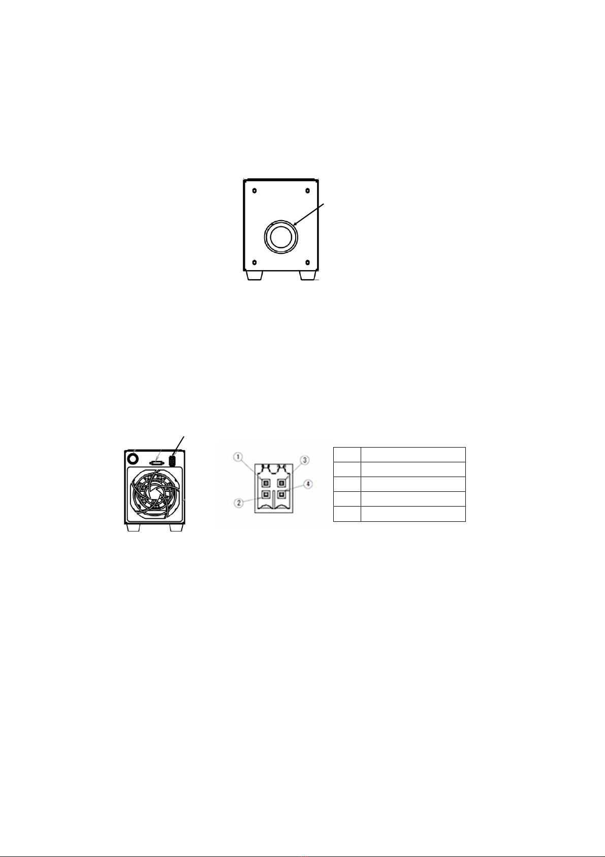
2-3-4 External trigger input and alarm output
If external trigger input or external alarm output is used, use a trigger / alarm connector at the rear
panel of EHD-SWIR series.
(a)
Trigger/alarm connector
(b)
Figure 7 Trigger/alarm connector at the rear panel of EHD-SWIR series
pin# Signal
1 Alarm Out (Collector)
2 Alarm Out (Emitter)
3 Trigger Input (Anode)
4 Trigger Input (Cathode)

11
/
14
3 Specifications
Table 2 Specification of EHD-2350SWIR / EHD-2500SWIR
Item Specs
Detector InGaAs / GaAsSb type-II quantum well
Wavelength range 1000nm to 2350nm (EHD-2350SWIR)
1000nm to 2500nm (EHD-2500SWIR)
Pixel number 320 (H) x 256 (V) / 9.6x7.68mm / ¾"
Frame rate,
exposure time
(100fps, 9ms), (100fps, 1ms), (150fps, 6ms),
(200fps, 4.5ms), (200fps, 1ms), (250fps, 3.5ms),
(300fps, 3ms), (320fps, 2.5ms), (320fps, 1ms)
Defect rate *1,2 < 1 %
Cooling Thermoelectric (TE) cooling
Bit length 16-bit (0 to 65535)
Interface CameraLink, Base configuration
16-bit x 1-tap (clock frequency: 48MHz)
Operation temperature 0 to +35 degC
Storage temperature −20 to +40 degC
Humidity 30 to 80%RH (non-condensing)
Supply voltage DC 24 V ±10 %
Power consumption ≤ 10 A
Power connector Hirose, LF10WBR-4P
Trigger/alarm connector Weidmuller, S2L-SMT 3.50/04/90G 3.2SN BK BX
Dimension 90 x 110 x 170 mm (except lens and projection)
Weight Approx. 2.5 kg
Lens mount C-mount
*1: Defective pixels include ones corrected in manufacturing and with output of zero value.
*2: Defective pixels increase in progress of time in principle.
EHD‐2350SWIR EHD‐2500SWIR

12
/
14
Table 3 Requirement of power supply for EHD-SWIR series
Item Specs
Output voltage*1 DC 24V
Maximum current ≥ 10 A
Voltage accuracy*1 ± 10 %
Voltage ripple *1 ≤ 480mVpp
Operation voltage & temperature Comparable to EHD-SWIR series
Storage voltage & temperature Comparable to EHD-SWIR series
Protective function Overload and overvoltage protection
*1: Specification at the output end of DC cable for power supply (5m length).

13
/
14
4 Operation
4-1 Start-up
(1) After making sure of connections between EHD-SWIR series, cables and the frame
grabber, switch on the PC and power supply.
(2) Start to supply +24V to EHD-SWIR series by the power supply.
(3) Wait for about 5 minutes for stabilization.
(4) Execute a sample software for image capture of an attached CD in the PC. The camera
setting, image capture and monitoring can be done by the software.
Regarding how to use the above software, refer to “user’s guide of sample software for image
capture” in the attached CD.
4-2 Shut down
(1) Stop the power supply.
(2) If EHD-SWIR series will not be used for a long time, it is recommended that the plug is
pulled out from the AC outlet.
4-3 External trigger input
EHD-SWIR series can capture images by not only its inner clock but also an external trigger. Its
circuit has an input insulated by photo couplers. Every rise to DC +24V in the trigger signal
executes one shot at the exposure time at current setting.
4-4 External alarm output
Not only to monitor inner status of EHD-SWIR series but also to output alarm from it can be done
by the software. Its circuit has an open collector insulated by photo couplers. When any error
occurs in EHD-SWIR series, it makes output pins short-circuited.
14
/
14
5 Maintenance
5-1 Camera body
In cleaning the camera body, remove the cables from it and attach the lens cap to the lens
mount. Cleaning the body with cables connected could result in electric shock. Use a cloth which
hardly generates dust such as nonwoven fabric. Do not use alcohol, thinner, benzene and strongly
acid or alkaline chemicals for cleaning.
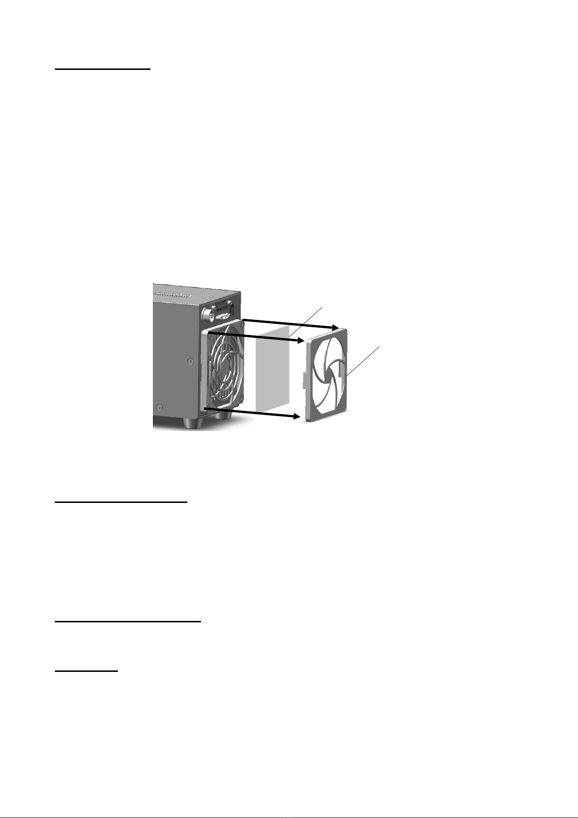
5-2 Air filter
When the air filter at the rear panel of E H D -SWIR series is soiled and blocked, take it off
together with a retainer as shown in Figure 8 and make it clean. If the air filter is dirty so that it
should be exchanged, make contact with us.
Air filter
Retainer
Figure 8 How to take the air filter off at the rear panel of EHD-SWIR series
6 Caution for export
This product corresponds to restricted goods and technologies established by export trade
control order and foreign exchange order. For import of this product, check demanders and their
purpose sufficiently and do necessary procedures such as export license application. Additionally,
make the end users of this product hold product records and prepare to disclose the records by
our request.
7 Caution for disposal
For disposal of this product, return it to us or distributors for this product.
8 Contact
Regarding information on this product, please make contact with:
EHD imaging GmbH
Zum Rennplatz 15, D-49401 Damme (Germany)
Tel: +49-5491-2090, email: [email protected]
Web: www.ehd.de
This manual suits for next models
1
Table of contents
Popular Digital Camera manuals by other brands

Minolta
Minolta SR-T 101 owner's manual

Niigata seiki
Niigata seiki MU-130 instruction manual

ADLINK Technology
ADLINK Technology NEON-1000-MDX Series user manual

Frontpoint
Frontpoint PREMIUM INDOOR CAMERA Get started

Olympus
Olympus Stylus Verve m-mini digital Advanced manual

Brickcom
Brickcom VD-200Np-S Easy installation guide


