Ei Electronics RadioLINK Ei262 User manual

Model Ei262
Read and retain carefully for as long as the product is being used. Contains vital information on the
operation and installation. This leaflet should be regarded as part of the product.
If you are just installing the unit, this leaflet must be given to the householder. This leaflet is to be
given to any subsequent user.
The RadioLINK Carbon Monoxide Alarm Ei262 will
communicate with all other RadioLINK devices including
Smoke/Heat/Fire Alarms, Relays and other accessories.
RadioLINK
MAINS POWERED
CARBON MONOXIDE ALARM
WITH RECHARGEABLE LITHIUM CELL BACK-UP
B16587-R0-262-UC-ENG 15/4/09 3:38 PM Page 1

1
2
3
4
5
6
7
8
9
10
11
12
13
14
IMPORTANT INFORMATION
What to do when you alarm is activated
CARBON MONOXIDE - THE SILENT KILLER
ALARM POSITIONING
INSTALLATION
4.1 Mounting & Wiring Alarms
4.2 RadioLINK Interconnecting etc.
4.3 Hardwired Interconnect
USING & TESTING YOUR SYSTEM
HOW TO DISTINGUISH BETWEEN CO ALARM & SMOKE ALARM WARNINGS
MAINTENANCE
LIMITATIONS OF CO ALARMS
HOW TO PROTECT YOUR FAMILY
GETTING YOUR CO ALARM SERVICED
FIVE YEAR GUARANTEE
TECHNICAL SPECIFICATIONS
ACCESSORIES
TROUBLESHOOTING
Page
CONTENTS
2
3
4
5
9
13
13
17
20
22
24
24
26
28
30
30
31
34
36
B16587-R0-262-UC-ENG 15/4/09 3:38 PM Page 2

1. IMPORTANT INFORMATION
WARNING: The Alarm should be permanently wired to the mains by a qualified electrician in
accordance with IEE wiring regulations (BS7671).
Install a Carbon Monoxide (CO) Alarm in every room that contains a fuel burning appliance, and in
rooms where people spend a lot of time e.g. bedrooms, kitchens and sitting rooms.
In rooms with an fuel burning appliance, install (preferably) on the ceiling (300mm from walls and
between 1m to 3m horizontally from appliance). In rooms remote from the appliance install at
breathing level, where the light indicators can be seen.
Regularly check that the green power light is on, so that rechargeable back-up cells will remain fully
charged. Important: The CO Alarm will not work if the mains supply is off and the rechargeable
cells are depleted.
Test the unit weekly by pressing and holding the Test/Hush button. The horn will sound and the radio
frequency (RF) signal will be transmitted. (Green light turns red while RF message is transmitted).
Replace sensor module after 5 years operation (see page 25).
When the CO Alarm detects abnormal levels of CO (above 50ppm CO) the red light starts to flash,
the horn will sound within 90 minutes and the RadioLINK signal will be transmitted. At higher levels
of CO the alarm will turn on sooner (see Table B - page 7).
The CO Alarm will automatically reset once the CO has cleared. Pressing the Test/Hush button will
silence the CO Alarm immediately (below 300ppm CO). If CO is still present the red light and horn
will turn on again after about 4 minutes.
The CO Alarm is no substitute for keeping chimneys and flues clear and in good condition, and all of your
appliances serviced regularly according to the manufacturer’s instructions.
Do not fit alarm until all building work is completed to avoid contamination.
3
?
?
?
?
B16587-R0-262-UC-ENG 15/4/09 3:38 PM Page 3

WHAT TO DO WHEN THE CARBON MONOXIDE ALARM IS ACTIVATED:
(1) Open the doors and windows to ventilate the area.
(2) Turn off all fuel appliances where possible. (The alarm can be silenced immediately, with
low levels of CO, by pushing the Test/Hush button).
(3) Evacuate the property leaving the doors and windows open.
(4) Get medical help immediately for anyone suffering the effects of Carbon Monoxide
poisoning (headache, nausea), and advise that Carbon Monoxide poisoning is suspected.
(5) Ring your gas or other fuel supplier on their emergency number. Keep the number in a
prominent place.
(6) Do not re-enter the property until the alarm has stopped. (If the alarm has been silenced
by pressing the Test/Hush button, wait at least 5 minutes. The alarm will then check that the
CO has cleared).
(7) Do not use the fuel appliances again until they have been checked by an expert. In the
case of gas appliances this must be a Registered Gas Installer.
Note: If the Ei262 Carbon Monoxide Alarm is interconnected to Smoke/Heat Alarms, quickly
press the Locate Button (on Remote Switches Ei411H3 or Ei1529) to silence all alarms
except the one sensing danger and/or find the alarm with the red light flashing rapidly. If it
is a carbon monoxide leak follow the above instructions. If it is a fire, evacuate the premises
closing all doors as you go , ring the fire brigade and follow the other smoke/heat alarm
emergency instructions.
4
?
B16587-R0-262-UC-ENG 15/4/09 3:38 PM Page 4

2. CARBON MONOXIDE - THE SILENT KILLER
2.1 WHAT IS CARBON MONOXIDE ?
Congratulations on becoming the owner of an Ei Carbon Monoxide Alarm. This will help protect you and
your household from the dangerous effects of Carbon Monoxide - The Silent Killer. Many are killed each
year, and many more suffer ill health from Carbon Monoxide (CO) poisoning (CO is the chemical symbol,
indicating the molecule has one carbon atom and one oxygen atom). CO is an invisible, odourless, tasteless
and extremely toxic gas. It is produced by appliances and vehicles burning fuels, such as coal, oil,
natural/bottled gas, paraffin, wood, petrol, diesel, charcoal etc. CO is absorbed by red blood cells in the
lungs in preference to oxygen - this results in rapid damage to the heart and brain from oxygen starvation.
High levels of CO in a house can be caused by:
•Incorrectly or poorly installed fuel-burning appliances.
•Blocked or cracked chimneys/flues.
•Blocked vents or draught-proofing which makes areas with fuel burning appliances or fireplaces airtight.
•Engines of cars, lawnmowers etc. left running in confined spaces.
•Portable paraffin or gas heaters in badly ventilated rooms.
•Charcoal barbecues burning indoors.
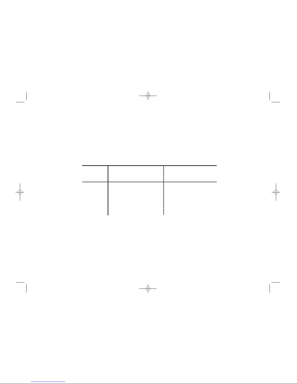
2.2 SYMPTOMS OF CARBON MONOXIDE POISONING
Most people know that high levels of CO are harmful, however the period of exposure is also important.
A low level for a long period (e.g. 150 ppm for 90 minutes) can cause the same symptoms (a slight
headache) as a high level of CO for a short period (e.g. 350 ppm CO for 30 minutes). Table A shows how
exposure to different concentrations of CO generally affects people.
5
B16587-R0-262-UC-ENG 15/4/09 3:38 PM Page 5

Many cases of reported Carbon Monoxide poisoning indicate that while victims are aware they are not
well, they become so disorientated they are unable to save themselves by either leaving the building or
calling for assistance. Young children and household pets may be the first affected.
Table A: Effects of Carbon Monoxide Poisoning
35 The maximum allowable concentration for continuous exposure in any 8 hour period according to OSHA *.
150 Slight headache after 1.5 hours.
200 Slight headache, fatigue, dizziness, nausea after 2-3 hours.
400 Frontal headaches within 1-2 hours, life threatening after 3 hours, also maximum parts per million in flue gas
(on an air free basis) according to US Environmental Protection Agency.
800 Dizziness, nausea and convulsions within 45 minutes. Unconsciousness within 2 hours. Death within 2-3 hours.
1,600 Headache, dizziness and nausea within 20 minutes. Death within 1 hour.
3,200 Headache, dizziness and nausea within 5-10 minutes. Death within 25-30 minutes.
6,400 Headache, dizziness and nausea within 1-2 minutes. Death within 10-15 minutes.
12,800 Death within 1-3 minutes.
ppm
Concentration
of CO in Air Inhalation Time (approx) and Symptoms Developed
ppm = parts per million
*OSHA = Occupational Safety & Health Association
6
B16587-R0-262-UC-ENG 15/4/09 3:38 PM Page 6

2.3 WHAT HAPPENS WHEN YOUR CO ALARM DETECTS CARBON MONOXIDE ?
When the Ei262 CO Alarm detects potentally dangerous levels of CO, it flashes the red alarm light and
then sounds a loud alarm if the CO persists and transmits a RadioLINK alarm signal.
Table B below shows how the CO Alarm reacts to different levels of CO gas and exposure time. At higher
levels of CO the alarm turns on sooner. The rate of flashing of the red light indicates the level of CO.
Table B: CO Alarm Response
* unless it has been in alarm (see 2.4 CO Alarm Memory overleaf)
If your CO Alarm sounds follow the instructions on page 4.
When ventilation is provided by leaving windows and doors open, the CO build up may have
dissipated by the time help arrives and the alarm may have stopped sounding. Although your problem
may appear temporarily solved, it is crucial that the source of the CO is determined and appropriate
repairs made.
NEVER IGNORE THE ALARM.
7
CO Level
(ppm)
Horn sounds
within
Red
Alarm Light
0
50
100
300
Off
60 to 90 minutes
10 to 40 minutes
3 minutes
Off *
1 Flash / 2 Seconds
2 Flashes / Second
4 Flashes / Second
B16587-R0-262-UC-ENG 15/4/09 3:38 PM Page 7

Pre-Alarm: When the alarm detects over 50ppm CO the red light flashes every 2 seconds. This helps
locate CO leaks as the unit gives a visable indication straight away (the horn will not sound unless the
50ppm of CO remains for at least 90 mins). Note the Pre-Alarm signal may be triggered by CO coming
for example, from cooking with gas, from car engines or from nearby barbecues. This is usually not a
concern unless the Pre-Alarm signal persists until the alarm sounds and the CO source is unknown.
Note: The CO Alarm may pre-alarm if cigarette smoke is blown into it, or aerosols are released nearby.
2.4 CO ALARM MEMORY
When the Test button is pressed the horn will sound, and the alarm red light will only flash if the unit has
previously detected CO and been in alarm. The flash rate indicates the level of CO detected as below:-
- Alarm Red light is Off – No CO detected since reset or power up.
- Alarm Red light flashes 2 times (in 2 seconds) every 40 seconds - 50 ppm CO detected for
approximately 90 minutes since reset or power-up.
- Alarm Red light flashes 4 times (in 2 seconds) every 40 seconds - 100 ppm CO detected for
approximately 40 minutes since reset or power-up.
- Alarm Red light flashes 8 times (in 2 seconds) every 40 seconds - 300 ppm CO detected for
approximately 3 minutes.
Reset Memory by holding down the Test button for over 20 seconds until the alarm red light stops
flashing. Cover the horn with a cloth to muffle the alarm during this time. (Note any other RadioLINK
device will also alarm during this period).
Please note that the memory will also be reset when the unit is removed from the mounting plate.
8
B16587-R0-262-UC-ENG 15/4/09 3:38 PM Page 8

3. ALARM POSITIONING
3.1 IDEALLY A CARBON MONOXIDE (CO) ALARM SHOULD BE INSTALLED IN:
- Every room containing a fuel burning appliance
- Remote rooms where occupants spend a considerable amount of time
- Every bedroom
However if the number of CO Alarms is limited, the following points should be considered when deciding
where best to fit the alarm(s)
- If there is an appliance in a room where people sleep, place a CO Alarm in this room
- Locate a CO Alarm in a room containing a flueless or open-flued appliance
- Locate a CO Alarm in a room where the occupant(s) spend most of their time (e.g. living room)
- In a bedsit, the CO Alarm should be placed as far away from the cooking appliance as possible, but
near to where the occupant sleeps
- If the appliance is in a room not normally used (such as a boiler room) the CO Alarm should be placed
just outside the room so that the alarm will be heard more easily
3.2 UNSUITABLE LOCATIONS
Do not place the CO Alarm in any of the following areas
- In the immediate vicinity of a cooking appliance
- Outside the building
- In an enclosed space (e.g. in or below a cupboard)
- In a damp or humid area
- Directly above a sink or cooker
9
B16587-R0-262-UC-ENG 15/4/09 3:38 PM Page 9

- Next to a door, window, air vent or anywhere that it would be affected by draughts
- Next to an extractor fan
- Where it would be obstructed, e.g. by curtains or furniture
- In an area where the temperature could drop below –10°C or rise above 40°C
- Where dirt or dust could block the sensor
- Where it could be easily knocked or damaged, or where it could be accidentally turned off or removed
- In a bathroom or other areas where the CO Alarm may be exposed to water splashes, dripping or
condensation (e.g. above an electric kettle)
- Near paint, thinners, solvent fumes or air fresheners
3.3 IF LOCATING THE CO ALARM IN A ROOM WITH A FUEL BURNING APPLIANCE (see Figure 1)
- If it is mounted on a wall, it should be located at a height greater than the height of any door or window
but still be at least 150mm from the ceiling
- If it is mounted on the ceiling it should be at least 300mm from any wall or light fitting
- The CO alarm should be a horizontal distance of between 1m and 3m from the potential CO source
- If there is a partition in the room, the CO Alarm should be located on the same side of the partition as
the potential source
- In rooms with sloped ceilings, the CO Alarm should be located at the high side of the room (see Figure 3)
3.4 IF LOCATING THE CO ALARM IN A BEDROOM OR IN ROOMS REMOTE FROM A FUEL
BURNING APPLIANCE (see Figure 3)
- Mount the CO alarm relatively close to the breathing zone of the occupants
Whatever position is chosen make sure it is possible to view the three light indicators, when in the
vicinity of the alarm.
10
B16587-R0-262-UC-ENG 15/4/09 3:38 PM Page 10

11
300mm
150mm
1 to 3 m
1 to 3 m
DEAD AIR
DON'T LOCATE
HERE
CO Alarm
Figure 1. Location in room with a fuel burning appliance
- 1 to 3m from appliance
- Ceiling 300mm (min) from walls - Wall 150mm vertically down from ceiling
B16587-R0-262-UC-ENG 15/4/09 3:38 PM Page 11

12
300mm
CO Alarm
CO Alarm
about
1 to 2m
Figure 3. Location in bedroom & rooms
remote from the appliance
Figure 2. Location in rooms with
sloped ceilings
- 300mm from apex of ceiling
- High side of the room
- Wall mounted
- Breathing level (approx. 1 to 2m
above floor)
B16587-R0-262-UC-ENG 15/4/09 3:38 PM Page 12

13
4. INSTALLATION
4.1 Mounting & Wiring your alarm
The Alarm is designed to be permanently
mounted, using its own built-in terminal
block to connect it to the mains wiring. The
mounting plate can be screwed directly to
the ceiling/wall. Alternatively it can be
screwed to a standard junction box (BS
4662 single gang accessory box). The alarm
requires a current of 90mA. The Alarm must
not be exposed to dripping or splashing.
There are important markings on the
underside of the alarm.
IMPORTANT PRECAUTION: Do not install
the actual alarm itself in new or
renovated buildings until all work is
completed (including floor coverings)
and the building has been fully cleaned.
The wiring can be installed when
appropriate. (Excessive dust and debris
from building work can contaminate the
sensor and cause problems, it will also
invalidate the guarantee). If it must be
installed, cover it completely, particularly
around the edges, with a suitable
covering, until all cleaning is finished.
LOCATION FOR
TAMPERPROOF SCREW
PUSH SMALL SCREWDRIVER
STRAIGHT IN TO RELEASE.
PUSH COVER AWAY FROM SCREWDRIVER
WARNING: DISCONNECT MAINS BEFORE REMOVING ALARM FROM
CEILING OR WALL
TAMPERPROOF CATCH
MOUNTING PLATE
SIDE VIEW
GAS ENTRY
HOLES
AMBER
FAULT LIGHT
RED - ALARM LIGHT
GREEN - POWER LIGHT AND TURNS
RED FOR RADIOLINK INDICATION
House
Code
Figure 4 - Alarm Installation & Removal
B16587-R0-262-UC-ENG 15/4/09 3:38 PM Page 13

The Alarm must not be connected when the house wiring insulation is being checked with high Voltages
i.e. do not use an insulation tester on the alarm.
Do not use the CO Alarm on an intermittent basis, or as a portable detector for the spillage of
combustion products from fuel burning appliances or chimneys.
Mains operated Alarms should be installed and interconnected by a qualified electrician in accordance
with the Requirements for Electrical Installations published by the Institution of Electrical Engineers (as
BS7671). Failure to install this Alarm correctly may expose the user to shock or fire hazards.
The Alarm must be continuously powered 24 hours a day so it is important that it is not on a circuit
that can be turned off by a switch.
Caution
Alternative Energy Sources – Wind, Solar, UPS etc.
This product must be connected to a Pure or True Sine Wave 230 Vac supply. It must not be connected
to devices giving a “Modified Sine Wave” or “Quasi Sine Wave” 230 Vac such as most inverters
connected to solar panels, wind turbines, water turbines or batteries.
This also applies to battery powered UPS (Uninterruptible Power Supply) inverters.
The will cause overheating, which will damage the product.
If you are not sure about your inverter or UPS type, please contact the supplier to verify.
Light Dimmer Circuits – The Alarms must not be powered through a light dimmer circuit. This will also
cause overheating and damage the Alarm.
INSTALLATION PROCEDURE
1. Select a location complying with the advice in the previous section.
2. Disconnect the AC mains supply from the circuit that is going to be used to power the Alarm.
14
B16587-R0-262-UC-ENG 15/4/09 3:38 PM Page 14

3. The house wiring must be connected to the terminal block on the mounting plate as follows:
L: Live - connect to the house wires coloured brown or marked L.
N: Neutral - connect to the house wires coloured blue or marked N.
IC: Interconnect - If you are only installing one alarm do not connect any cable to the IC terminal.
As well as the hard wired interconnect the Ei262 also provides a wireless interconnect to other
RadioLINK devices. See page 17 for information on interconnecting.
Warning: Mixing the Live and Neutral connections when interconnecting alarms will damage all the alarms
- ensure that the same colours are used throughout the premises for Live, Neutral & Interconnect wires.
We strongly recommend that you check for the following before connecting the alarm:
• check for Live and Neutral using a two probe tester.
• check for Live using a neon tester.
• check that the Interconnect wire is NOT connected to Live, Neutral or Earth. Do not use an Earth wire
for the Interconnect line.
Note:The Alarm does not need to be earthed. However the terminal marked is provided for the convenience
of the installer so that any copper Earth wire or cable coloured green & yellow, can be safely terminated.
4. Lift off the wiring cover as shown in Figure 5 overleaf.
5. If the mains wires are being brought along the surface, conduit can be inserted into the top and/or
bottom of the mounting plate.
(a) position the mounting plate, so that the cable conduit is as shown in Figure 5 overleaf.
(b) Carefully cut around the knockout on the outside wall so the conduit fits. (Note: to comply with the EN
60529, IPX2D protection rating, seal around conduit with silicone rubber or similar to prevent water entering).
6. If the mains wiring is recessed, bring the wiring through the rear hole in the mounting plate as shown
in Figure 6.
15
B16587-R0-262-UC-ENG 15/4/09 3:38 PM Page 15

7. Carefully align the mounting plate and screw into place. Connect the wires to the terminal block. With
recessed wiring, ensure the rear gasket seals around the edge of the hole in the ceiling or wall. This is
to prevent air draughts affecting the CO gas entering the alarm. If the hole is not closed off by the gasket
it should be sealed with silicone rubber or equivalent.
Note: House wiring should not be “bunched up” in the area of the alarms but quickly and neatly directed
away. This will minimize their effect on the radio aerial.
8. Replace the wiring cover.
9. Carefully line up the unit on the base and slide on.
10. It is essential to House Code the RadioLINK Ei262 to ensure they will not accidently
communicate with nearby systems (even if you do not plan to use the RadioLINK feature yourself).
This is easily done as explained in Section 4.2.
L N IC
EARTH (IF PRESENT)
L - LIVE
N - NEUTRAL
IC - INTERCONNECT
TERMINAL SCREWS
RECESSED WIRING AREA
MAINS WIRING
16
L N IC
KNOCK OUT FOR
SURFACE WIRING
CONDUIT
WIRING
CONDUIT
INSERT SCREWDRIVER TO LIFT
AND REMOVE WIRE COVER
KNOCK OUT
FOR SURFACE WIRING
CONDUIT
SEALING GASKET
(MUST BE IN PLACE)
WIRING
CONDUIT
Figure 5 - Surface Wiring Figure 6 - Recessed Wiring
B16587-R0-262-UC-ENG 15/4/09 3:38 PM Page 16

(As a safety feature the units will all communicate with each other (provided they are within range) as installed i.e. without any House
Coding. The repeater function is disabled when units are not House Coded).
11. Connect the mains power to the alarm circuit. Check the green light is on.
The CO Alarm is now fully operational and will provide protection against a build up of Carbon
Monoxide gas after it has been connected to the mains supply for over 70 seconds.
12. Press the Test/Hush button for 5 seconds. The horn will sound. The ‘power’ green light will then turn
red and the RadioLINK signal will be transmitted. Check that any interconnected alarms also sound
within this period.
13. The unit may be tamperproofed further by removing the knockout in the sidewall of the mounting plate
(as shown in Figure 4) and inserting the self tapping screw (3mm diameter, 12mm long) after the unit
is on the mounting plate.
4.2 RadioLINK for interconnecting etc.
The Ei262 will transmit an RF alarm signal when it detects potentially dangerous levels of CO.
This RadioLINK Alarm signal can be used to:
1. Wirelessly interconnect to other Ei Electronics
RadioLINK Smoke/Heat Alarm devices (e.g. Smoke/Heat
Alarms mounted on Ei168RC RadioLINK bases), so that all
units will go into alarm when the Ei262 senses alarm levels
of CO gas and also the Ei262 will go into alarm when the
other devices sense fire.
A combined maximum of twelve Ei262 CO Alarms may be
interconnected along with an Ei161RC/Ei164RC/
Ei166RC/Ei2110 Smoke/Heat/Fire Alarms on an Ei168RC
RadioLINK Base provided an Ei411H3 Remote Control
is used in the system (see “ACCESSORIES” section).
17
B16587-R0-262-UC-ENG 15/4/09 3:38 PM Page 17

If interconnected CO and Smoke/Heat Alarms are all sounding, the
LOCATE switch on the Ei411H3 Remote Control should be pressed. This
will just leave the alarm that triggered the system sounding.
This is very important to determine because the actions to take in each
situation are very different.
In the case of CO the premises should be fully ventilated by opening doors
and windows. The user should call the gas supplier etc.
In the case of fire, doors and windows should be closed to slow the spread
of fire. The user should call the fire brigade etc.
2. Wirelessly communicate with Ei Electronics RadioLINK accessories
such as the Ei428 RadioLINK Relay (e.g. for shutting off gas valves) and
the Ei411H3 Remote Control.
4.2.1 Interconnection
After all the RadioLINK devices have been installed they must all be house
coded as follows:
Housecoding your alarm
1. Press and hold the housecode switch on the bottom of the cover with a small screwdriver until the
green power light turns red (see figure 7).
2. Immediately release the switch and the light will flash red (alternating with green) quickly a few times.
The red light will then flash every 5 or 10 seconds (depending on number of units coded - see below).
Repeat this action on all other RadioLINK Ei262 units in the property as quickly as possible (within 15
minutes).
3. Now put any other RadioLINK devices in the property into house code mode (see their separate
instruction manuals for details) within 15 minutes.
18
HOUSECODE
SWITCH
GREEN POWER LIGHT TURNS
RED FOR RADIOLINK INDICATION
House
Code
Figure 7
B16587-R0-262-UC-ENG 15/4/09 3:38 PM Page 18

4. Check that the RadioLINK Ei262 is house coded to all the other RadioLINK devices in the property by
counting the number of times the red light flashes (alternating with the green) every 5 (or 10) seconds.
For example, with just the Ei262, on its own, in the “system” it will give one red light flash every 5 seconds,
with 3 units in the system should give 3 short flashes every 5 seconds, 4 units should give 4 short flashes
and so on, up to 12 units. It may take up to 30 minutes for all the units in the system to be House Coded
correctly. Check that the other RadioLINK units are house coded as per their instructions. If at the end
of this period certain units do not show the correct number of flashes, repeat the process (from point 1
above) once more and if this fails see - Section 14 Troubleshooting on page 36.
5. The units will automatically exit the House Code learn mode after 30 minutes however we recommend
that you manually exit the House Code mode by pressing and holding the House Code switch on the
Ei262 until the RadioLINK Indicator light turns red, and then release. The RadioLINK Indicator light
should stop flashing and an 'exit House Code' signal will be sent to all other units.
Check that the RadioLINK Indicator lights on all other units have stopped flashing red. (If some units are
still flashing it may indicate a problem with the radio communication from this unit to the other units, or
these devices may have to be taken out of house code mode manually, see their instruction manuals).
Repeat the process once more and if this fails see - Section 14 Troubleshooting on page 36. Manually
exiting the House Code mode reduces the risk of accidentally House Coding your RadioLINK devices
with nearby systems.
6. Check the communications by pressing the test/hush button on the Ei262 for up to 10 seconds. The
alarm will sound and then pause briefly while the RadioLINK signal is transmitted. The green power light
will turn red for this duration (approx 3.5 seconds). All other alarms should sound (this may take up to 20
seconds as the message may need to be relayed through repeaters). Release the test button. The local
alarm will cease and you should then be able to hear the other alarms sounding in the distance and then
stopping. Note: The local alarm may sound again depending on the number of repeaters in the system
as it acknowledges the repeated signals. Similarly check each RadioLINK device in the same way (if any
of the alarms do not sound, see - Section 14 Troubleshooting on page 36.
19
B16587-R0-262-UC-ENG 15/4/09 3:38 PM Page 19

When button testing units in sequence it is important to wait 15 seconds plus a further 6 seconds per
repeater between button tests (e.g. for a system with 10 repeaters, time to wait: 15 seconds + 10 x 6
seconds = 75 seconds between button tests).
Finally attach the label provided to the distribution board to identify the alarm circuits.
(Note: If it is necessary to clear House Codes see section 12, page 32 - Technical Specification).
The “Repeater” Function
All Ei262 CO Alarms are set as “Repeater” units as supplied. The function of a Repeater unit is to receive
and then re-transmit the RF signals. This provides multiple signal paths throughout the installation to give
improved RF signal reliability (with 3 or more RadioLINK units).
Note the “Repeater” function is not operational until all the units are put in to House Code mode.
The operation of the “Repeaters” can be observed as each unit turns on its RadioLINK Indicator light as a
RadioLINK message is being repeated.
(Note: If it is necessary to disable the Repeater function see section 12, page 34 - Technical Specification).
4.2.2 RadioLINK Accessories
When using RadioLINK accessories simply install all the devices as per their instructions first. Then
follow the house coding and checking procedure described in 4.2.1 above.
4.3 Hardwired Interconnect - The Ei262 also provides a facility for hardwired interconnection:
With interconnected alarms, when one unit detects CO all units alarm. All horns will sound but only units
detecting CO will flash their alarm red lights.
A combined maximum of twelve Ei262 CO Alarms may be interconnected along with an Ei128RBU &
Ei128COV relay module (see “ACCESSORIES” section).
Alternatively, up to twelve Ei262 CO Alarms and Ei161RC/Ei164RC/Ei166RC/Ei2110 Smoke/Heat/Fire
Alarms in total, may be interconnected provided an Ei1529RC Remote Control is used in the system
(see “ACCESSORIES” section).
20
B16587-R0-262-UC-ENG 15/4/09 3:38 PM Page 20
Other manuals for RadioLINK Ei262
1
Table of contents
Other Ei Electronics Carbon Monoxide Alarm manuals

Ei Electronics
Ei Electronics Ei 220E User manual

Ei Electronics
Ei Electronics Carbon Monoxide Alarm Ei206D User manual

Ei Electronics
Ei Electronics Ei 261D Manual

Ei Electronics
Ei Electronics Ei207 Series User manual

Ei Electronics
Ei Electronics Ei261ENRC User manual

Ei Electronics
Ei Electronics Carbon Monoxide Alarm Ei220EN User manual

Ei Electronics
Ei Electronics Carbon Monoxide Alarm Ei220EN User manual

Ei Electronics
Ei Electronics Ei207/208 Series User manual

Ei Electronics
Ei Electronics Ei208 Series User manual

Ei Electronics
Ei Electronics Ei 261DEN User manual