Eico 232 User manual

~
co
to)
~
~
r-
~
'"
-4
;;a
m
, m
~-4
-
rn
W
z:
-
g:J
en C"')
It
'"
•••••
=
W
0
:::a
0
c::
rn
•
"
3:
~
:(
rn
W
~
rn
C"')
••
::z
•••••
~
-t
:::a
-0
:-<
C"')
=
=
::z
-
...•
..•
C"')
~
-
0
::I
••••
r'

..
~
+110
..
:I
%
0
o
+~
0
..
~
I--.+-
II +30
~ ~'I'
o ..•.
i' -
I'
o
+:ro
~'j
j
+10
"
~
*
10
~~
0.1
r
Ii
i
II
1.0
,
,
4 S ,
1. '1000
...:=.t=
, t
f
1.=
I--k+f
17"++-1-
A.C.
VOLTS (RMS) MIASURED ACIOSS 600 _OHM IIS'STlYI LOAD
.:.'.::
1
J.
1
11
-1--I---H·W.W-l+I+-'-j--·
--'
-r-
1-
2 1 4 S ""
101
Fig.l
REPLACEMENT PARTS LIST
~7:;::?':ifi;; ~ifif' 'h",
{'.,-~~~~?;f:~"r
-':
':
~
~:,.~~.~
general description
""l'"
-.'. :;'Ex.preuly designed for TV servicing, the Model 232 (249) Peak-to-
,.P,
~Pe1 kVTVM features. a full-wcve , high frequency rectifier circuit that re-
sponds to and measures' the peak-to-peak voltage value of complex and sine
waveforms even when DC is present. It also reads the rms voltage of sine
waves (on a separate scale), de voltage values, and resistance values. For
consistantly high accuracy, there are seven non-skip ranges on a II functions
to provide a uniform 3 to 1 scole ratio between adjacent ranges.
DIICIIIITION _THoNG. IVM. DISCItIIlTION
10033 R19 Rill.
I
:l.3MO
I
l;2W, 20%
11049
R16
"
70KO, 1/2W, 1%
1003•• R2 S
"
".7MQ ,1/2W, 20% 11050 Rl7 "20KO, 1/2W, 1%
1040-\ ~28
"
02MQ, I/2W, 10% 11051 R18
"
10KO, 1/2W, 1%
10406 R20,21" 6800, I/2W, 10% 11052 R3
"
325KO, 1/2W, 1%
10407 Rl
"
lMO, 1/2W, 10% 11700 R4 "9001<0 lW, 1%
10503 R26
"
33K, 1/2W, 5% 11701 R12 "7MQ, iw, 1%
10520 R24 "
68K,
1/2W, ~% 16000 R22,30
n
pot., 2 KO, linear
10521 R23
"
47K, 1/2W, 5% 18014 R31,32 pot., 2 KO, linear
10524 R29 "lBMO, 1/2W, 5% 18015 R27 pot., 1OKO, linear
11025 R2 "150KO, 1/2W, 1% 20003 ct cap., .1 mf - loo0V
11026 R15 "2001<, 1/2W, 1% 20007 C4 cap., .003mf-400V
11037 R9
"
9000, 1/2W, 1% 20012 C2, C3 cap., .025mf-400yr
11038 RB,
"
9KO, 1/2W, 1% 23010 C5 cap., elec. 10mf,150
11039 R7 "90KO, 1/2W, 1% 56000 BT1 battery, 1 1/2 V
11043 Rll
"
9.70, 1/2W, 1% 60024 52 switch, range
11044 RIO
"
90Q, 1/2W, 1% 60025 51 swItch, function
11045 R6
..
9001<0, 1/2W, 1% 72004 Ml meter, 4Q()ua
11046 R5
..
9MO, 1/2W, 1% 90013 VI tube, 12AU7
11047 R13 "2MO, 1/2W, 1% 90017 V2 tube. 6AL5
11048 R14
"
7001<0, 1/2W, 1% 92000 11* bulb, '47
*Model249 only 93003 CRt rect.,35ua
'7
=r
-+-
-t.
r-
t--
I
The input resistance on all dc voltage ranges is 11 megohms, which
, is high enough to prevent loading error and yet not so high as to Impair the
stabilityof the instrument. The dc voltage ranges may be extended t030,000
volts (with accessory High Voltage Probe HVP-l or HVP-2) and may also be
'used for RFvoltage measurement up t0250 mc (with accessory RF Probe Model
PRF-ll). The frequency response ofthe ac voltage ranges extends from 30 cps
to 3 mc. for a source of 100 ohms or less.
Facilities that Increase the accuracy, versatility, and ease of oper-
ation include zero- center Indication for discriminator alignment and bias
measurements; zero adjustment unaffected by changing function or range;
separate scale for low ac voltage measurement; electronic protection against
meter burn out; adjustment of all calibration controls without cabinet removal;
and UNI-PROBE, a single unit probe used for all functions. ••
The Model 232 (4 1/2" meter) and the Model 249 (7 1/2" meter)are
identical electrically. Where portability Is desired, the-Model 232 is pref-.
erable because of Its extremely compact design. The Model 249 is an ideal
bench instrument, having extra long scales to minimize reading errors. and per-
mitting permanent placement of the equlpmentat a practical working distance.
Both instruments are ruggedly housed, professional in appearance, and highly
dependable and trustworthy measuring devices that will prove extremely val-
uable in television, fm-om radio servicing, and many industrial applications.
speclfl catlo ns
DC VOLTMETER:
Ranges .•.•..•............•.. 0 to 1.5,5, 15,150,500,1500 volts
Input Resistance ..•.•..•.•..••. 11 MQ
Accuracy ...•...•.•...•.••.••• ±3% of full scale or better.
Range extended to 30,000 volts with High Voltage Probe HVP-l or HVP-2
(l 090 MQ Multiplier resistor recommended).

AC
VOl, TMeTER:
RMSvcslues of Sine Wave•..... 0 to 1.5 volts on separate LOW-AC scale
o
to 5,15,50,150,500,1500 volts
Peak-to-Peak Valuesof Sine .. , 0 to 4 volts on separate LOW-.AC stelle
&
Complex Waves 0 to 14,42,140,420, 1400, 4290;;yoIts ,
Input Resistance
&
Capacity •.• , 1 MQ, shunted by 60 rnmf"
(apRro <'. )
Accuracy ..•.•••••.•••.•.•• ±5% of full scale or better:", "',,:,. ,',
Frequency Response •••••...•. 30 cps to 3 Mc(source Z 100 Q or less} . '"
RFvoltage measurement to 250 Mc (accuracy ± 10%) with ~F Probe PRF""11
OHMMETER: 0 to 1000 Megohms in 7 ranges- RXl ;RXW,RX1
9
0
,RX1000
RX10K,RX100K,RX1Meg (10 ohms center scale on RXl range)
TUBECOMPlEM ENT: 1-6AL5 twin-diode as full-wave peak-to-peak rectifier"
1-12AU7 twin-triode in vacuum-tube balanced bridge circuit
Ionium ructlfleri 1.5 volt flashlight
, OWER SUPPLY:
II.
POWI.R
RrOlJIRrMINIS, 10 I?S volts AC, 50-60
CPSi
drain: 5 watts
OVERALL
SIL. :,
MOII,,17a~"1\
1/)"11,
~11'Wi
S"dl Model
249 -
81/2 'h ; 13"w
15"~
WEIGHT: Model 232-7 rid., MIlII,,1~4')-? pounds
CASE: Steel cabinet, aroy wllnklll flllhh, .,dIIl
M
ollllt1l1lulll peno l, doop..etched
and rub-proof
IJPpilod
complete with UNI-PROBE (combined isolating and direct probe,
used for all functions and ranges) and ground lead.
operation
PRELIMINARYADJUSTMENTS
1. Connect the UNI-PROBE to the VOLTS-OHMS terminal, and the Ground
Cable to the GND. terminal.
2. Plug the line cord into an outletsupplying 105-12SvoltsAC, So-60cps.
3. Set the FUNCTION selector at "+DC VOLTS" and the UNI-PROBE at
"DC". Allow several minutes for the instrument to warm up. If necessory,
use the ZERO ADJ. control to set the meter pointer within scole limits during
-2 -
-1
,
'
,.,..
..
:
.r
....
the worm-up period.
4.,
Short the UN I-PROBE to the Ground Coble and set the meter pointer
at the I~ft:'hand zero with the ZERO ADJ. control. If turning the FUNCTION
selector J~~ (;l.PCVOL TS
i'
changes the position of the meter pointer, readjust
the ~ec~ankgl zero of the meter as described under MAINTENANCE.
5. SetA~e FU~CTION selector at "OHMS", the UN I-PROBE at "AC-
OHMS", and the RANGE selector at "RXl 0". Separate the UNI-PROBE from
Ground Coble , The meter pointer should move to approximately full scale.
6. Use the OHMS ADJ. control to position the meter pointer on the last
j'graduation of the scale.
7. Set the FUNCTION selector at "AC VOLTS". If the meter pointer
does not read zero volts when the RANGE selector is at "1.5 V", refer to the
':' AC Voltmeter Balance Adjustment" and "AC Voltmeter Calibration"sections
under Maintenance.
Note: Although the meter is protected against burn-out under ordinary over-
loads, repeated overloads may impair the accuracy of the movement. For this
reoson, in the following Instructions the operator is advised to first make a
trial measurement at a range setting higher than the voltage expected.
DC VOLTAGE MEASUREMENT
1. Set the UNI-PROBE at DC and the FUNCTION selector at either
"+DC VOLTS" or "-DC VOLTS", depending upon the polarity of the voltage
to be measured with respect to ground.
2. Set the RANGE selector at a position considerably higher than the
voltag~ to be measured.
3. Connect the Ground Coble to the ground side of the voltage being
measured and touch the UNI-PROBE to the high side.
4. Reset the RANGE selector to the position which gives a reading near-
est to fuII sea Ie and read the dc vo Itage on the meter.
ZERO CENTER INDICATION
Zero-center indication permits observation of either positive or negative
vo Itage excursions without resetting of the function selector. To prepare the
instrument for zero-center Indication, simply set the FUNCTION selector ot
• "+DC VOLTS" and turn the ZERO ADJ. control (with no voltage applied) un-
-3- '

III
tllll
11I111111
pclnter Is sot at tho con tor
10-0
1
10•
Tho range selector should
be
Itli
ftr$1
to a position at lacst twlco tho voltage to be measured and then to
rhe lowest position which permits the meter pointer to remain on the scal~.
The valuo of a positive voltage (deflection to the right of the center ",-0+")
is obtained by subtracting half the range selector setting from the dC'~oltage
reading on the scale. The value of a negative' voltage (deflection
jo.rhe
left'
of the center "-0 +") is obtained by subtracting the dc voltage reading on the
scale from half the range selector setting.
""'<':.,'
RESISTANCEMEASUREMENT
Remove all power from the equipment under test before making resistance
measurements so that no voltages are present.
1. Set the UNI-PROBE at "AC-OHMS" and the FUNCTION selectcr ot
"OHMS".
2. Set the RANGE selector at "RX10".
3. Short theUNI-PROBE to the Ground Coble. The meter pointer should
be at the left-hand zero. Use the ZERO ADJ. control to reset the pointer at
the left-hand
"0" ,
if
necessary.
4. Separate the UNI-PROBE from the' Ground Cable. Tho motor pointer
should be at the last line on the "OHMS" scale. Use tho OHMS ADJ. control
to reset the pointer at the lost line on tho "OHMS" scole, If necessary.
, •• 11111111rl
1'110
clip
(1)
tho GI'ound Coble to one terminal of tile resist-
11I11'/1
III
1m
11It1l1llll'tld
and touch the UNI-PROBE to the other terminal.
6. Reset the RANGE selector to give a convenient deflection and mul-
tiply the reading on the" OHMS" scale by the factor indicated at the RANGE,
selector setting.
Caution: Meter movements, thermocouples and other low-current, low-
resistance devices may be damaged unless a range above "RX10" is used. At '"
the "RX1" and "RX10" positions, the instrument applies up to 1.5 volts to the,
resistance under measurement.
RESISTANCEMEASUREMENT ABOVE 1000 MEGOHMS
The upper limit of direct resistance measurement with this instrument is
1000 megohms. The leakage resistance of small paper and mica capacitors
usually exceeds the value. To measure resistance values above 1000 meg-
ohms, an external de voltage source between 20 and 500 volts can be used to
·4·
:-
----:::::-~:-~--:-:
..
(,;:).,::~,;:
:'."
,-
"."
obtain a measurable pointer deflection. The circuit connections are shown in
Fig.2.and the procedure is as follows.
J
.·S~j.t_he FUNCTION selector at "+ DC VOlTS" and the UNI-PROBE at
"DC";','
2'. Measure the' voltage at point A and then the voltage at point B.
3. Compute the resistance from the following formula.
Rx (megohms)
=
11 [<Volts at "A") - <Volts at "B")]
(Volts at "B")
Example: In measuring a resistance by the method of Fig. 2, the externclde
voltage supply is 300 volts. The instrument measures 300 volts at point A and
1.1 volts at B. Then,
Rx
=
11 (300 - 1. 1)
=
3000 megohms (approx.)
1.1
A ,Rx
B
+
DC Supply
.:1
11
Ftg.2
AC VOLTAGE MEASUREMENTS
1. Set the UNI-PROBE at "AC-OHMS" and the FUNCTION selector at
.•."AC VOLTS".
2. If necessary, use the ZERO ADJ. control to set the meter pointer at the
left-hand "0".
3. Set the RANGE selector at a position considerably higher than the v.ol-
tage to be measured.
4. Connect the Ground Cable to the ground side of the voltage sourcet,o
be measured and touch the UNI-PROBE to the high side. -
·s·

'), 1{"lal tho RANGEselector to the position which gives a reading nearest"
full scele and read the ac voltage.
NOTE: All RMSscales are inblack with full-scale values of 1
,:~:,:5·,
i5,5()~'
500, and 1500 volts. All peak-to-peakscales are in.red with full;.s:Cah~.;"alue$ .'.
4,14,42,140,420, 1400, and 4200 volts. When the instrument
is
se.t at the
1.5 vo It range, the RMS or P-P sca Ies on the lowest arc (deslqricted as LOW-~
AC) are read; on higher ranges, the scales on the two center arcs are
reed.
Itshould be noted that the fixed ratio of 2.83 to 1between corresponding peck-
to-peak and rms scales is derived from the relationship between the peak-
to-peak and rms values of a sine wave. There fore, while peek-to-peck read-
ings are valid regardless of whether the waveform is complex or sine, rmsread-
irigs are valid only for sine waves. Note also that the time delay between the
instant the leads are removed from the source being measured and the Instcnt
the meter pointer returns to zero is normal and is the result of ci~cuit constants
sel·ected to permit accurate measurement of recurrent pulses with low repefl-
tion rates. '
applications
This instrument may be used fo maintain and service television receivers,
frn-om and communication receivers, transmitters, audio equipment, and pul-
sed electronic and electro-mechanical equipment. Indicative of itsversatllity
are some of the special applications described below.
9;?CJLLATQR
SiRlIrQJ~_./fI.f;.~~.V.BfMr.~T:
Tho negative dc voltage devel-
rId
II
alway. directly proportional to the strength' of
1111
1lllIthm. rltl_
voltago can be measured very readily at the oscillator grid
willi., tit" lxmd
.wltch Is turned to the various bands, and in each of its posi-
tions the main tuning condenser is rotated from minimum capacity. This wi·11
give an indication of the strength of oscillation at all frequencies within. fhe
oscillator's range.
AVC-VOLTAGE MEASUREMENTS: The automatic volume control voltage de-
veloped by the fncomlng signal can be measured at a number of places, in the,
receiver. This negative voltage first appears across the diode load resistor. It,
may also be measured along the avc bus and at the grids of the rftubes being,
controlled, The dc voltage measured at the diode load resistor Is a very con-
venient output indication during receiver alignment.
Owing to the high input resistance of this instrument, it is p,ossible to meas-
ure bias (avc)voltage on the grid of rf and if amplifier tubes without disrupting
the signal. '
DC SUPPLY VOLTAGE MEASUREMENTS: Power supply dc voltages can be
·6·
',",
,t·~
5' •..
.
~
~-
:.:. -=::::::::.:7....:.
',1 ;~~
';, measured at the rectifier filaments and in the filter circuits. Plate, screen,
and cathode dc voltages can be measured at the corresponding pins of the tube
sockets ..
BIASCEL~:VOLTAGE MEASUREMENTS: This instrument wiIIaccurately meas-
ure the,vortag'e of a bios cell. Current drawing voltmeters are not capable
'bf making this' measurement and in many cases wiII damage the cell.
'f
1
.~j DETECTION OF GASSY TUBES: One effect of a gassy tube is to reduce the
normal negative gri,d bios, or even make the grid positive. This instrument is
ideal for measuring the voltage directly at the control grid of any tube in
.<'.
order to determine whether or not this effect is present. Excessive gas will
, couse the tube to cease operating normally, and in an audio amplifier will
uSlJOllycause the volume control to become noisy. This amount of gas will
not always produce a noticeable change in the operation of the radio receiver.
J
, Consequently if repeated difficulty is experienced with volume controls be-
.~ . coming nolsy in this type of circuit, this instrument should be used to check
' •.~ for incorrect bias.
"f
.~
.,
.
,T
OUTPUT INDICATION: To measure output in the alignment of am and TV
receivers, the instrument is prepared for dc voltage measurement and usually
connected to the load resistor of the, second detector while the circuit com-
ponents are adjusted for optimum output. In an fm receiver, the instrument is
connected across the limiter load resistor. The zero-center feature' is very
useful for the alignment of fm discriminators.
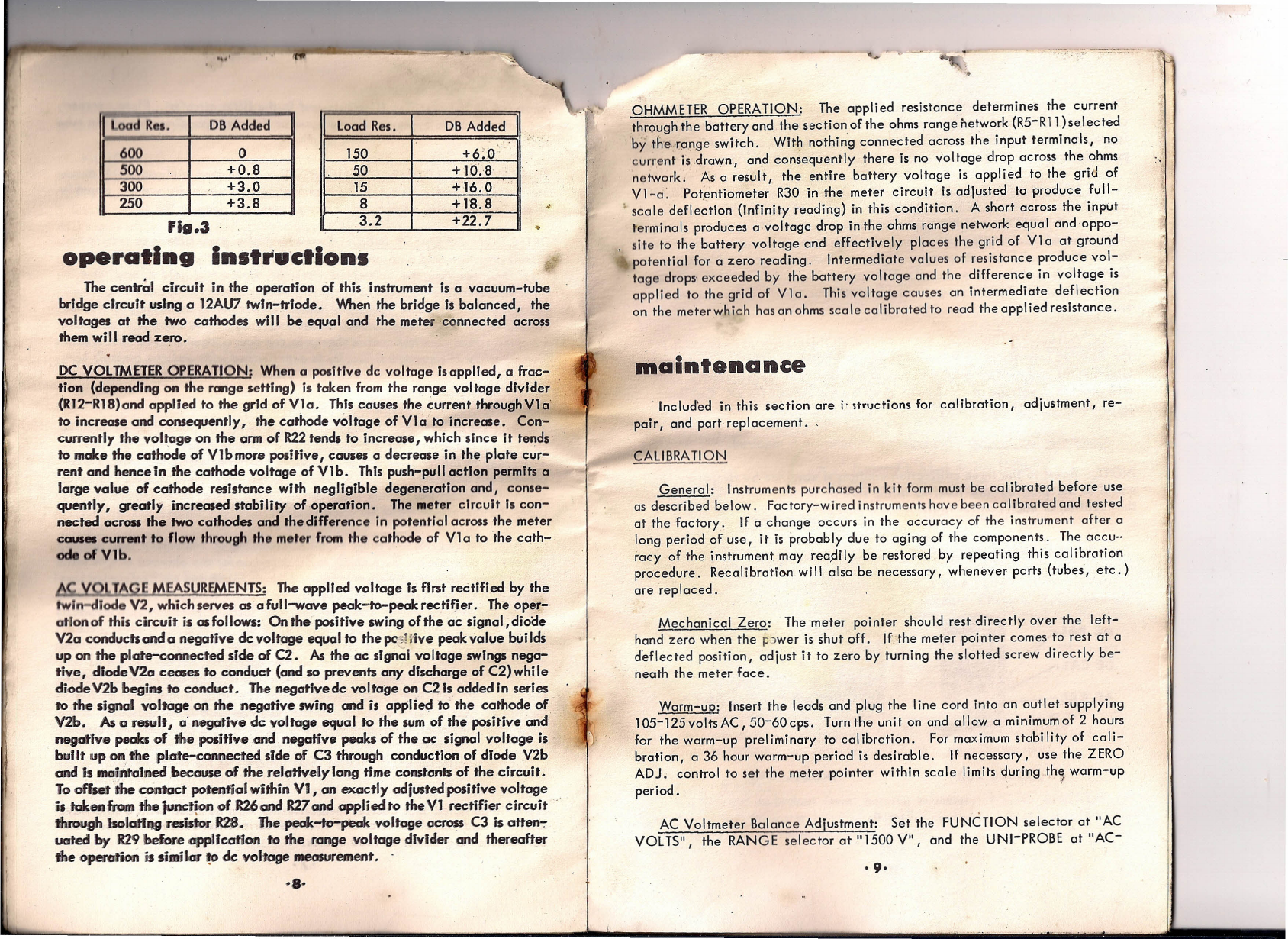
DBMEASUREMENTS: In order to avoid crowding of frequently used scales,
there is,no db scale on the meter. Another reason for the absence of this scale
is that there are many different reference levelsin use and each reference level
results in a different scale. Fig. 1 is a graph for one accepted reference level,
namely 0.775 volts across 600 ohms resistive load (1 milliwatt), with which
rms cc voltage readings can be converted to db readings. However, the db
-vclue
read 'from the chart is correct only when the voltage reading has been
taken across a
600
ohm resistive load. If the reading has not been taken across a
'600 ohm load, the db value read from the chart must be corrected by adding
algebraically to it the correction 'increment specified in the chart of Fig. 3
for the particular resistive load. If the resistive load is not included in the
chart,the correction increment maybe calculated from the following formula.
Correction Increment
=
10 log 600 (where R is the resistive load)
R
It should be noted that decibel measurements must be mode with a sine wave
form to avoid waveform error and that the correlation between decibels and
ear response is greatest at 1000 cyc les.
·7·

..
,'
-.~
.--
Load Rea. DBAdded
600 0
500 +0.8
300
.,
+3.0
250 +3.8
load Res. DBAdded
':
"
ISO +6:0.'
SO + 10'.8
15 +-1-6.0
8+1'8.8
3.2 +22.7
fig.3
operating
Instructions
The centr~1 circuit in the operation of this instrument is a vacuum-tube
bridge circuit using a 12AU7 twin-triode.
When
the bridge Is balanced, the
voltages at the two cathodes will be equal and the meter connected across
them will read zero.
DC VOLTMETEROPERATION; When a positive de voltage isapplied, a frac-
tion (depending on the range setting) Is taken from the range voltage divider
(R12-R18)and applied to the grid of VIa. This causes the current throughVla
10
increase and consequently, the cathode voltage of VIa to increase. Con-
currently the voltage on the arm of R22tends to increase, which sInce It tends
10
make the cathOde of Vlbmore positive, causes a decrease in the plate c~r-
rent and hencein the cathode voltage ofVlb. This push-pull action permits a
large value of cathode resistance with negligible degeneration and, conse-
quently, greatly increased stability of operation. The meter circuit Is con-
nected across the two cathodes and the dIfference in potential across the meter
causes current to flow through the meter from the cathode of VI a to the cath-
ode
ofVlb.
I\\,
yV ..IAyl:
mEASUREMENTS: The applied voltage is first rectified by the
twln-dlode V2, which serves as a full-wave peak-to-peak rectifier. The oper-
atlonof this circuit is as follows: On the positive swing of the ac signal,dioae
V2a conducts and a negative dcvoltage equal
10
the pcslrlve peak value builds
up on the plate-coMected side of C2. As the ac signal voltage swings nega-
tive, diodeV2a ceases to conduct (and so prevents any discharge of C2)while
diode V2b begins to conduct. The negative dc voltage on C2 is added in series
to the signal voltage on the negative swing and is appli~ to the cathode of
V2b. As
0
result,
0'
negative de voltage equal to the sum of the p<)sitiveand
negative peaks of the positive and negative peaks of the ac signal voltage is
built up on the plate-connected side of C3 through conduction of diode V2b
and
is moi,~tained because of the relatively long time constants of the circuit.
To offset 'the contact potential within VI, an exactly adiusted positive voltage
is takenfromtheJunc~on of
R260nd R27and
applied to theVl rectifier circuit
tIuough lsolatiqg resistor
R28.
the peak-to-pi Ok voltage across C3 is otten-:-
uoted
by 129
beforeopplication to the range voltage divider and thereafter
the operation is similar ~ de voltage measurement.
-8-
..
-----:-.:;-:-.
-:-:::-~:~~~-:-:-
OHMMETER OPERATION: The applied resistance determines the current
through the battery and the section of the ohms range network (R5-R11)selected
by the range switch. With nothing connected across the input terminals, no
current is.drawn, and consequently there is no voltage drop across the ohms
network, As a result, the entire battery voltage is applied to the grid of
VI-a: Potentiometer R30 in the meter circuit is adjusted to produce full-
>
scale deflection (infinity reading) in this condition. A short across the input
terminals produces a voltage drop in the ohms range network equal andoppo-
site to the battery voltage and effectively places the grid of V1a at ground
potential for a zero reading. Intermediate values of resistance praduce vol-
tage drops' exceeded by the battery voltage and the difference in voltage is
applied to the grid of V1a. This voltage causes an intermediate deflection
on the meterwh ich has an ohms scale cal ibrated to read the appl ied resistance.
mal,ntenance
lncluded in this section are
i'
srruc+lons
for cal ibration, adjustment, re-
pair, and part replacement.
CALIBRAnON
General: Instruments purchased in kit form must be calibrated before use
as described below. Factory-wired instruments have been calibrated and tested
at the factory. If a change occurs in the accuracy of the instrument after a
long period of use, it is probably due to aging of the components. The occu-
racy of the instrument may recdi ly be restored by repeating this calibration
procedure. Reccl
ibrcflon
will also be necessary, whenever parts (tubes, etc.)
are replaced.
Mechanical Zero: Themeter pointer should rest directly over the left-
hand zera when the p;)wer is shut off. If the meter pointer comes to rest at a
deflected position, adjust it to zero by turning the slotted screw directly be-
neath the meter face.
Warm-up: Insert the leads and plug the line cord into an outlet supplying
105-125voltsAC,50-60cps. Turnthe unit on and allow a minimumof 2 hours
for the warm-up preliminary to calibration. For maximum stability of cali-
bration, a 36 hour warm-up period is desirable. If necessary, use the ZERO
ADJ. control to set the meter pointer within scale limits during the warm-up
• d
f
perlo .
AC Voltmeter Balance Adjustment: Set the FUNCTION selector at "AC
VOLTS", the RANGE selector at "1500 V"
I
and the UNI-PROBE at "AC-
. 9·

OHMS".
Short
the UNI. .PROBEto the Ground Coble and use the ZERO ADJ.
control to ••
t
the meter poInter exactly at the left-hand zero. Keeping the..
lead•• horted, felet the RANGE selector at "1.5 V" and use the AC Balance
potentiometer
I
R27, to reset the meter pointer at the left-hand zero ..
.,
AC Voltmeter Calibration: Set the FUNCTION select~r'~t
"AC;::
vons",
the RANGE selector at "150 V", and the UNI-PROBE at "AC-OHMS". Con-
nect the UNI-PROBE and the Ground Cable across the 117 volts AC supply.
Adjust the AC Calibration potentiometer, R32, until the meter reads 117 rms
volts. If the maximum accuracy of which the instrument is capable is desired
(±5% of full scale), apply exactly 150 volts (60 cps) on the "150 V" range
(or 50volts on the "50 V" range) and adfust R32 for exactly full-scale deflec-
tion.
DCVoltmeter Calibration: Set the FUNCTION selector at "+ DCVOLTS",
the RANGE selector at "5 V", and the UNI-PROBE at "DC". Connect the
UNI-PROBE and the Ground Coble across two flashlight cells in series, which
will provide a voltage of 3.10 volts when fresh. Adjust the DC Calibration
potentiometer, R31, until a 3.10 volt reading is obtained on the meter.
Ohmmeter Calibration: No separate calibration is required.
~
_,'" i
NOTE: Acess to the three calibration controls Is obtained by temporary re-
moval of the plug-buttons Inserted in the side of the cabinet. Fig. 4 shows
the location of each control in Models 232 and 249.
"
~"iiWC"'fiIf'.'".'%_,."" :,,~.':-, ..,'.'.::.~i~".__
AC CAL.
......,,~..,.<..... ..•..
;.,..l
~:ft1~.~~~:;~~CCAL.
• ,. ~'l~
'~ ACBAL.
~~
MODEL 3
MOD~L
49
Fig.4
'10'
---..----- ->~--.,-- -,,-.
-0',
i'
~~..;
,
TUBEREPLACEMENT
When a new tube is lnsrclledln the instrument~"&fmay be necessary to re~
zero when switching from the lowest to the highest dc-voltage ranges unless
the tube lsoqed by operating it in the instrument for 36 hours. The calibration
hould be checked ,~fter this period.
BATTERYREPLACEMENT
Do not permit on exhausted battery to remain inside the instrument case
as the chemicals from a deteriorated battery may damage the components.
Indications of a weak battery will be found in the trouble-shooting section.
TROUBLE-SHOOTING THEMODEl. 232 or 249
Asan aid to local izing the cause of fau Ity operation, the following general
trouble-shooting procedure has been prepared. Obviously all possible troubles
can not be listed and the technician should use the schematic diagram to trace
down unlisted troubl~s. In general, newly constructed kit instruments should
be given a through, step-by-step check=of the wiring, following the tables
and pictorial diagrams in the construction book, in case the trouble is not
li's;,fedor carinot be corrected by checking the listed possible causes.
Instrumen~ fai Is to operate on a II functions; tubes do not light
1. Line cord broken or not making contact at outlet.
2. Switch section SID defective.
3. T1 defective: Check for shorted or open windings.
Tubes light; ZERO ADJ. does not work properly; meter pointer does not move
or bangs to right or left.
1. Inc~rrect operating voltages on bridge tube VI.
a. No B plus or B minus voltage present: Check CRI ,C5, Tl high
voltage winding, R26, R27, and R24 with ohmmeter; check connections
between
.these
components also.
b.
B
plus and B minus voltage present: Open or short in VI circuit .
c. VI defective: See" Tube Replacement" .
2. Switch section S1-C defective or wired incorrectly.
3. Defective meter movement.
4. ZERO ADJ. control erratic in operation: Potentiometer R22 is de-
fective; replace with new control. NOTE: First make sure mechanical zero
of pointer is correct. See "Mechanical Zero" under Calibration.
Meter pointer sticks
1. Crocked or broken jewel bearing in meter. NOTE: Individual re-
placement parts for meter movement are not available. Meter should be re-
turned for repairs or replaced with new meter.
·11·

"
otlon ortl .11functions
1. Loose or bad connectloris in probe or cables.
2. Wiper contact on SIB or SIC defective.
3. Loose or bad connection in bridge circuit wlrln'g, including meter
terminals. With power applied, probe wiring and components with insulated
probe.
4. VI defective. Replace as described under "Tube Replacement. ','
5. CRI Intermittent.
Instrument fails to operate on OHMS; works normally on ac and dc voltage
measurements.
I. Battery exhausted or not making contact.
2. Defective wiper contact on switch section S2C.
3. "OHMS" contact (terminal 7) on SIB defective.
4. Open circuit In resistor network or burned out resistor around switch
section S2C. Check continuity of network R5 through RII. NOTE: This net-
work is made up of resistors which are added In series as switch is rotated.
Therefore, one faulty resistor may cause improper operation on one or more
ranges.
5. Loose or broken "Ohms" contact on switch section SIC (termlnel
L)
OHMS ADJ. fails to give infinity setting on "OHMS" scale.
I. Battery exhausted.
2. OHMS ADJ. potentiometer, R30 defective.
3. VI defective. See" Tube Replacement" .
Re.l.tgnce readIng. Inaccurate on lome or all "ohms" ranges.
I. One or more resistors In network around switch section S2C have changed
value.
2. Excessive leakage In "ohms" circuit. " Check switch wafers on S2C
and SIB fordlrt or damage. NOTE: High humidity may cause leakage and in~
accurate readings on high ohms scales. Bake out inside of Instrument with
I aht bulb.
3. Shorted wiring In resistor network around S2C.
4. Faulty or high-resistance connections in "ohms" circuit.
Instrument falls to operate on anyac voltage range; works normally on OHMS
and DC VOLTS.
I. V2 defective. See "Tube Replacement."
2. AC volts contact on SIA, SIB, SIC, or S28 defective.
3. Faulty wiper contact on S2D.
4. Open or short In circuitry associated with V2. Check out wiring and
components values with ohmmeter.
5 • CI , C2, or R29 open; C3 shorted.
·12·
/0
Meter
Ic .
I. "AC Balance" potentiometer R27 out of a I~stment. Readjust as de-
scribe under" "AC Voltmeter Balance Adjustment." If adjustment cannot be
made, then , "
2. R28 or R27 Is defective. Check value with ohmmeter.
AC voltage readings Inaccurate on some or all ac ranges; performance on ohms
god dc voltage ranges is normal.
I. Defective contacts or wipers, or excessive leakage In S2B. Check for
loose or dirty contacts.
2. V2 defective. Install new 6AL5. See "Tube Replacement."
3. (2 or C3 leaky.
4. R29 chonged in volue. Check with ohmmeter.
If instrument is inaccurate on 500 and 1500 volt ranges only, check contacts
10 and 11 on S2D and also R2, R3, and R4. If inaccurate on 1.5 volt range
only, replaceV2. See "Tube Replacement."
Instrument foils to operate on any range of "+VOLTS'" or "-YOL TS"; works
nQrmally' on ohms and ac volts.
1. UNI-PROBE resistor is open. Try applying low dc-voltage with UNI-
PROBEset at "AC-OHMS". If reading Is obtained (about 10% high), replace
UNI-PROBE resistor.
2. DC voltage contacts on switch sections S2A, SlB, or SIC are de-
fective. Check for loose or broken contacts.
Voltage readings inaccurate on "+VOL IS". "-YOLTS", ac voltage a,nd re-
sistance readings are correct.
1. R31out of adjustment. Reset as described under "DC Yoltmeter Cali-
bration.
u
2. UNI-PROBE switch is shorted, resulting in readings about 10% high
on all +DC and -DC voltage ranges. Use ohmmeter to check for short be-
tween input and output of probe at "DC" position as well as "AC-OHMS"
position.
3. Resistances in network around S2A has changed value. Check with
ohmmeter and replace defective resistors.
EICO Repair Service
If your instrument foils to function properly and the ccuse of the trouble can
not be found with the trouble shooting information provided, you may return
it to the EICO repair department where it will be repaired at a charge of $5.00
plus the cost of ports. If your instrument has been built from the kit form,
refer to the complete statement of the EICO servicing policy in your con-
struction book. (Note: Please includeUNI-PROBE when returning instrument
for repa Ir. )
·13·

-
III
?fi;:::'::~o7"::''':::h-='·",~:'~ =~':7_t.:;
• ·1t_1olIItlftelhDlfMwif •. "..., •••• front•
.
.
.
I
+1 CS
120VAC'
I
J.~;
_"'V
I
I...
x
GlUNj
,,)0\(
Jj
111
-i:3:3'
l~-
W2-IAU -, .
ci
C2 '. _".: -.' .
J.'
, : J _
~III
':' x
". FJ
~~ '--f---~' ~ ,~_
53 /.
'.
"',./
R6
11
u
nCf?J •••••••
MJ..."
ill
III
.h ..~
In bottwry,
I I;2V
R4
Cl
cap.,
.1
mf _
lOOOV
15
C2.C3
cap.,
.025.' -
4OC)V
16
CO
"'P •••
003'" -
'OOV
t7
<:$
cop.,
.IK.
10"'-I.50V ••
01
Net ••
as
MCI
19
11' _lb,
'1,7
110
IU __
,400-.
III
11 ,..., lMQ,I/2W .12
II
NI..,
15<*0,1,I2W,l" .13
a •••..
32.5KQ.l/2W.l"
-, lzIL _
--
~AC"'L.
121
121
132
124
BLACK
+•..•
110
~
fUNCTION SWITCH 51
•••••• _ ,U •• hc l-rM
th oe
III
- e
cou •••• .....:Iocl< •••
lu
e
1tl
on-
POllllon" S.ttl ••
g
•.••• , 9OOKO, IW,'" 114 •.•••• 7001(0, lJ2W,
I'"
•.••. , 9MO, I;2W, ''''' 115 •.••.• 200K,
l/lW, '''''
•.•••• 900KQ, l~. 1""
116 •.••.•
701C0,' l;2W,
''I.
•.••.•toKQ~ I;2W, 1••
It7
,..,2OKO, I;'2W,'"
::: ::Q,
~~:;
: :..:::
~. ~~:.
1••
•.••.• 900, I;2W, 1... 120..21,.. .• 6800, l/.ZW
NI.,
9.7~ lj2W, ,••. R22,.30,.:at., UO, Itn••.
•.•••• 7MO, lW,
1"...
It23 •.••• ,
47K,
I;2W
•.•••• WO,
1/2W.'''''
124 •.••.•
681(, lj2W
• MoeNI 2.' ••
Iy
125 ,•• , ".7MQ. 1/8
1t26 , •• ,
331:,
112
R27
pot.•
101C0•••••.
128 ,. .• 82MQ. 1.
129
rei.,
lIMO.
I,
l:n,32
pot.,
2ICQ,u.--
SI _1tcJ.a,~
12 •••.Itch.,....
VI tube, 12AlD'
V2 tube,6AU
'elltl.. Seith,•
on
N;.VOLTS
-tIC VOLTS
+OCVOlTS
OHM'
MODELS 232. 249
PEAK TO PEAK YTYMS
~ mSiaUNEN'f co., DlC.
R£,v.IO·C,¥
'ANGE SWITCH S2
1.5V, RX 1
'V,, X
10
15V,lX 100
.5OV, R X 1000
lSOV, It X 10K
5OOV.
IX
lOOK
1500V.IXIM
'i t'e~
This manual suits for next models
1
Table of contents
Other Eico Measuring Instrument manuals
Popular Measuring Instrument manuals by other brands

Status Pro
Status Pro T430 user guide

Alpha Moisture Systems
Alpha Moisture Systems dewTEC DS2000 instruction manual

Tecnogas
Tecnogas HT-89 Operation manual

Fluke
Fluke 43B Getting started guide

Endress+Hauser
Endress+Hauser tmt142 Brief operating instructions

multicomp pro
multicomp pro MP001186 instruction manual