Eicor 230 User manual
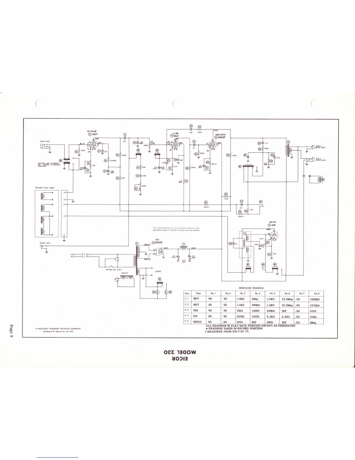
PrroTotrACT* FolJ.* ffitcoR,
dnoDEr 230
st
o
g
EI
:l
lr|
o
o
=REWIND.FORWARD
CONTROL VOLUME
ON-OFF
CONTROL TONE
CONTROL RECORD-LISTEN
CONTROL
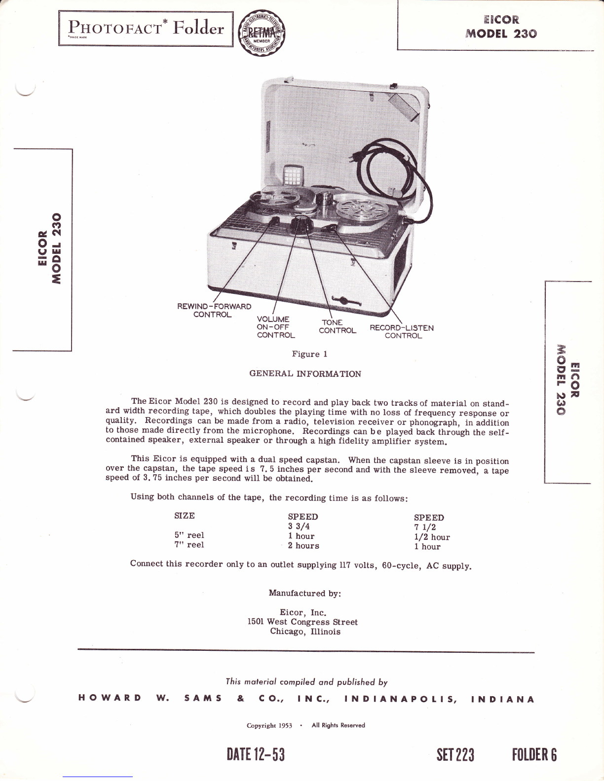
Figure 1
GENERAL INFORMATION
The Eicor Model 230 is designed to record and play back two tracks of material on stand-
ard width recording tape, which doubles the playing time with no loss of frequency response or
quality. Recordings can be made from a radio, television receiver or phonograph, in addition
to those made directly from the microphone. Recordings can b e played back thiough the self -
contained speaker, external speaker or through a high fidelity amplifier system.
This Eicor is equipped with a dual speed capstan. When the capstan sleeve is in position
over the- capstan, the tape speed i s ?. 5 inches per second and with the sleeve removed, a tape
speed of 3.75 inches per second wiII be obtained.
using both channels of the tape, the recording time is as follows:
3
8s
rnl"i
FO
t9F
(.)
o
SIZE
5" reel
?tt reel
SPEED
3 3/4
t hour
2 hours
SPEED
7 L/2
L/2 hour
L hour
Connect this recorder only to an outlet supplying Il? volts, 60-cycle, AC supply.
Manufactured by:
Eicor, Inc.
1501 West Congress Street
Chieago, Illinois
fhis molerial compiled ond published by
sAxrS & co., tNc., INDIANAPOLtS,
C.opyright 1953 . All Rights Reserved
INDIANA
DATE 12-53 srT 223 FOTDER 6
HOWARD l^f.

Figure 2
To Start-
Turn
Volume-
OPERATING CONTROLS
volume control knob (9) clockwise.
Degree of rotation of volume control knob
determines volume of recording and play back.
Tone-
Tone control knob (I0) controls tone and operates
only for play back.
Tape Travel-
Rewing-Stop-Forward control knob (I) controls
direction of tape tlavel. Always return this knob to
"Stop" position before turning unit off.
Record-Listen-
Record-Listed control knob (ll) controls amp-
Iifierand record playback head. To prevent acciden-
tal erasur€, place in "Listen" position immediately
after recording is completed.
OPERATING INSTRUCTIONS
1. Insert the AC power cord into the receptacle
on the right side of the top plate.
Page 2
2. PIug the AC cord into a convenient wall re-
ceptacle of the proper rating.
@1. Place a reel of tape (either 5" or ?") on the
left spindle (23) and an empty reel on the right spindle
(43) making sure the reel slots engage the reel pin on
the spindles.
2. Thread the tape by following the solid printed
line on the top panel (Fig. 1).
NOTE: This recorder uses Type "A" wound tape ,
i. e. the d u I I magnetic coated side faces
inwardonthe reel. If thetapeused is
Type "8" (coated side facing outward) the
recordingwill bemade at avery lowsound
level and the playback will be almost in-
audible.
3. Insert the free end of the tape through to the
hub of the right reel and place a pencil firmly over
the tape, fbrcing it into one of the three radial slots.
Turn the reel several turns (counterclockwise) with
the pencil in this position until the tape i s secured to
the reel and all slack is taken up between reels.
Setting Tape Speed-
The Eicor i s equipped with a quick change dual
speedcapstan. When thecapstansleeve (8)is in
(e)

11
Figure 3=
9s
rnfi
FO
pF
ot
o
position over the capstan, the tape speed will be T. b
inches per se cond and with the sleeve removed, a
tape speed of 3.75 inches per second will be obtained.
Because the tone fidetity will vary with the speed
of the tape, a compensating cireuit activated by the
slide switch located next to the green indicator light
has been provided. For operation with the capstan
sleer/e in position, the switch button should be in a
fuII left position and when operating with the sleeve
removed, the switch button should b e placed in a full
right position.
NOTE: For recording speech, the slower speed
is excellent and allows the maximurn r€:
cording and playing time. For higher
quality recording as is desired for music
reproduction, the faster speed is best.
To Record From Microphone-
1. Turn the volume control knob (9) to the right
until a click is heard and allow about thirty seconds
for the amplifier to warm up.
2. Insert microphone plug into input socket
labeled "Micro".
3. Turn record-listen knob (1I) to "Record" po-
sition. When in record position the red Iight on the
right side of the top plate will come on.
4. While talking into the microphone, adjust the
volume control until the neon indicator light flashes
slightly.
NOTE: Correct recording volume is very impor-
tant. T o o weak a signal, which does not
cause the neon indicator to flash, will re-
sult inweak playback and high background
noise. Too strong a signal, causing the
indicator to flash constantly, will result
in distortion during playback.
To Record From Radio-
Recordings can be made from a radio by placing
the microphone near the loudspeaker of the radio;
however, this type of recording may not be satisfactory
as other sounds m a y be picked up by the microphone
which as a result will be recorded on the tape. A su-
perior quality recording can be made by use of the
radio-phono attachment cord which is supplied with
the recorder. Connect attachment cord as follows:
1. Connect the cord clips across the voice coil
terminals on the radio speaker.
2. Insert the attachment cord plug into the socket
labeled "Radio".
3. Proceed as described
Microphone".
NOTE:
in "To Record From
cord after recording
Remove attachment
is completed.
To Record From Phonograph-
1. Connect the cord clips of the attachment cord
to the pickup Ieads on the phonograph.
Page 3
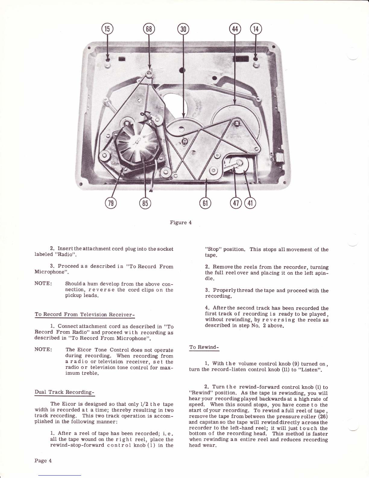
Figure 4
2. Insert the attachment cord plug into the socket
Iabeled "Radio".
3. Proceed as described in "To Record From
Microphone".
NOTE: Should a hum develop from the above con-
nection, reverse the cord clips on the
pickup leads.
To Record From Television Receiver-
1. Connect attachment cord as described in "To
Record From Radio" and proceed with recording as
described in "To Record From Microphone".
NOTE: The Eicor Tone Control does not operate
during recording. When recording from
a radio or television receiver, set the
radio o r television tone control for max-
imum treble.
Dual Track Recording-
The Eicor is designed so that only l/2 t h e tape
width is recorded at a timel thereby resulting in two
track recording. This two track operation is accom-
plished in the following manner:
1. After a reel of tape has been recordedl i. e.
aII the tape wound on the right reel, place the
rewind-stop-forward control knob (l) in the
Page 4
"Stop" position. This stops all movement of the
tape.
2. Remove the reels from the recorder, turning
the full reel over and placing it on the left spin-
dle.
3. Properlythread thetape and proceedwith the
recording.
4. After the second track has been recorded the
first track of recording i s ready to be played,
without rewinding, by reversing the reels as
described in step No. 2 above.
To Rewind-
1. With the volume control knob (9) turned on,
turn the record-Iisten control knob (It) to "Listen".
2. Turn t h e rewind-forward control knob (I) to
"Rewind" position. As the tape is rewinding, you will
hearyour recordingplayed backwardsat a highrate of
speed. When this sound stops, you have come t o the
start of your recording. To rewind a full reel of tape ,
remove the tape from between the pressure roller (26)
and capstanso the tape will rewinddirectly acrossthe
recorder to the left-hand reel; it will just touch the
bottom o f the recording head. This method is faster
when rewinding an entire reel and reduces recording
head wear.

Figure 5=
9=
tnfl
FC)
trl F
G'
o
To Play a Recording-
1. Thread thetape as described under "Thread-
ing the Tape".
2. Turn the On-Off Volume control knob (9) on
and allow approximately thirty seconds f o r the tubes
to warm up.
3. Place the record-Iisten control knob (ll) in
the "Listen" position.
4. Place the rewind-stop-forward control knob
(l) in the "Forward" positiori and ad just the Volume
and Tone control to the desired level.
To Use an External Speaker-
Anysize speaker of the permanentmagnet typ€,
having a 3.2 O voice coil, may b e used by connecting
the attachment cord across the v o i c e coil terminals
of the speaker and then inserting the plug of the attach-
ment cord into the socket labeled "3. 2 Q Speak".
To Edit and Splice Tape-
NOTE: Since it is impossible to edit and splice
one track without affecting the other, re-
cordings which are to be edited should be
' limited to one track only.
1. The tape maybe editedby cutting outunwanted
portions, or by joining selections into another se-
quence. Announcements may be inserted between
selections, etc. Unusedsections of tape canbe spliced
together for re-use.
2. For best results, cut tape at a slightdiagonal ,
join ends together with splicing tape on the glossy side
and trim off any excessive width.
Erasing Recorded Material-
Itis notnecessary tofirst erasea recorded tape
if the same tape is to be used f or a new recording.
Erasing of recorded material takes place automatically
when new material i s recorded. If it is desired only
to erase a tape, set the machine for recording without
having the microphone or attachment cord connected
to input jacks.
DISASSEMBLY INSTRUCTIONS
To remove the recorder from its cabinet, dis-
connect the line cord and remove the f our No. I0
Phillips head wood screws (I3) at the corners of the
top panel (12). Insert a thin-blade screwdriver between
the panel and the cabinet and pry upwards enough to
slip the f ingers under the panel. Lift up enough to
permit the speaker plug to be disconnected from the
amplifier. The recorder can now be removed com-
plete.
In handling the recorder out of its cabinet, care
must be taken to avoid damage to the motor fan (85)
Page 5
and the m o t o r shaft. When replacing the recorder ,
check to be sure the speaker leads and the motor leads
will not be pinched or will not interfere with the re-
corder mechanism.
MECHAMCAL DRIVE ASSEMBLY
1. With the rewind-forward control knob (l) in
the "Stop" position, idler wheel (22) should be in a
neutral positionl that is, there should be a clearance
of. l/32" between the motor shaft and the idler wheel.
2. Withcontrolknob (I) inthe "Rewind"position,
idler wheel (22) is pivoted against the rewind drum
(23) and the motor shaft" This accounts for the fast
rewind speed. Make a check, by turning the rewind
drum(23) counterclockwise, to see if theseparts con-
tacteach other properly. The idler wheel should turn
the motor shaft. If this does not oecur, check for
binding parts, oil on the friction surfaces, or loose-
ness of springs (57 and 6?.A).
3. When control knob (l) is in the "Forward"
position, idler (22) is pivoted against the capstan (30) ,
andthe "O" ringbelt (40), which isdriven bythemotor
belt pulley (16), is pivoted againstthe rim of the take-
up drum (44).
4. With the motor running and the control knob
(l) in the "Stop" positionthere shouldbe at least lrl32"
clearance between belt (40) and take-up drum (44).
5. With the motor running and control knob (f)
in the "Stop" position, observe belt (40). The same
portion of the belt surface should run in the pulley
grooves at all times, that is the belt should not rotate
about the center of a cross section. If such rotation
does occur, belt pulley (t6) is not correctly located.
6. Checkend play of the rewind drum (23), cap-
stan drum (30) and take-up drum (44). Each should
have some end play, not more than /32". Correct
assembly of washers on these shalts should control
this.
7. With control knob (I) in "Rewind" position,
there should be at least /32" clearance between the
rubber on the brake (49) and the take-up drum (44) .
With the motor running, move the control knob slowly
from"Rewind" to"Stop". Meanwhile, rolate the take-
up drum (44) manually. The brake should contact the
take-up drum before the rewind drum stops rotating.
Bend the brake arm to meet these requirements.
8. Place a full 5" reel of tape on the take-up
shaJt (43) and run the machine in the "Forward" po-
sition. Measure the tension required to hold the tape
reel stationary. This tension shouldbe I to 2 ounces.
NOTE: This tensionshould be measured after the
machine has been running with the clutch
slippingfor at least one minute. The ten-
sion is controlled b y the type and amount
of lubricant used on the felt washer.
9. Place a f ull 5" reel of tape on the rewind
drum (23) and measure the tension required to pull
tape off the reel. The tension should be 3/8 to 3/4
ounce. The tension is eontrolled by the type and
amount of Iubricant used on the felt washer.
I0. Check functioning of pressure roller (26) by
holding tape disc(43) on take-up drum (44) and letting
tape run through capstan. If tape does not run through
smoothly, check to s e e if pressure roller surface is
clean and spring tension on arm is adequate. The
pressure roller shaJt should be well oiled. The pres-
sure roller in contact should be flush up against the
capstan.
TROUBLES
Take-Up Drum and Capstan Speed lrregular-
1. Grease or oil on the rubber surface of idler
wheel (22), motor shaft, pressure roller (26), "O"
belt (40) and take -up drum (44). Clean these parts
with naptha.
2. Motor belt pulley (16) Ioose.
Taoe Overruns When Control Is Turned
From "Rewind" to "Stop" Position-
@justedproperly.
(See "Mechanical Drive Assembly" #?).
Tape Will Not Rewind-
1. Springs (57 and 6?.A) loose.
Tape WiIl Not Run Forward-
1. Springs (57 and 6?A) Ioose.
LUBRICATION
Extreme care must be taken when lubricating
the mechanism. For satisfactory operation, the in-
structions in this section should be followed.
1. Mechanical Iinkages should be Iubricated
lightly at points of friction with Sta-Put No. 18-H.
2. The shafts of rotating parts, when replaced,
should be wiped clean with a lint-free cloth or paper
and oiled lightly with Kensington No. 9 Spindle Oil .
Use two or three dropsl
3. Whenlubricating thefelt washers on thetake-
up and rewind drum, use Sta-Put Oil No. 360. Sat-
urate the felt washers and then remove as much of the
oil as possible by pressinga cloth or absorbent paper
against them.
Page 6
=
gtr
mfl
FO
)9v
G}
o
e.---@
H"--o
e
e..iq f*g
ffl @'-*@
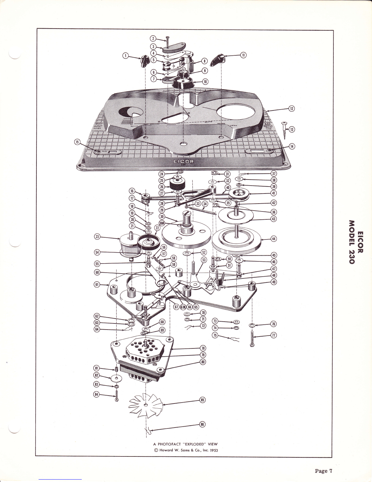
A PHOTOFACT "EXPLODED'' VIEW
@ Howord W. Soms & Co., lnc. 1953
6--_d
@-*rt
.^. \-
ar__*6
*€
3\ASb
?50'
4:@-
Page 7
(0
o
F{
t
b0
.t{
Fr{
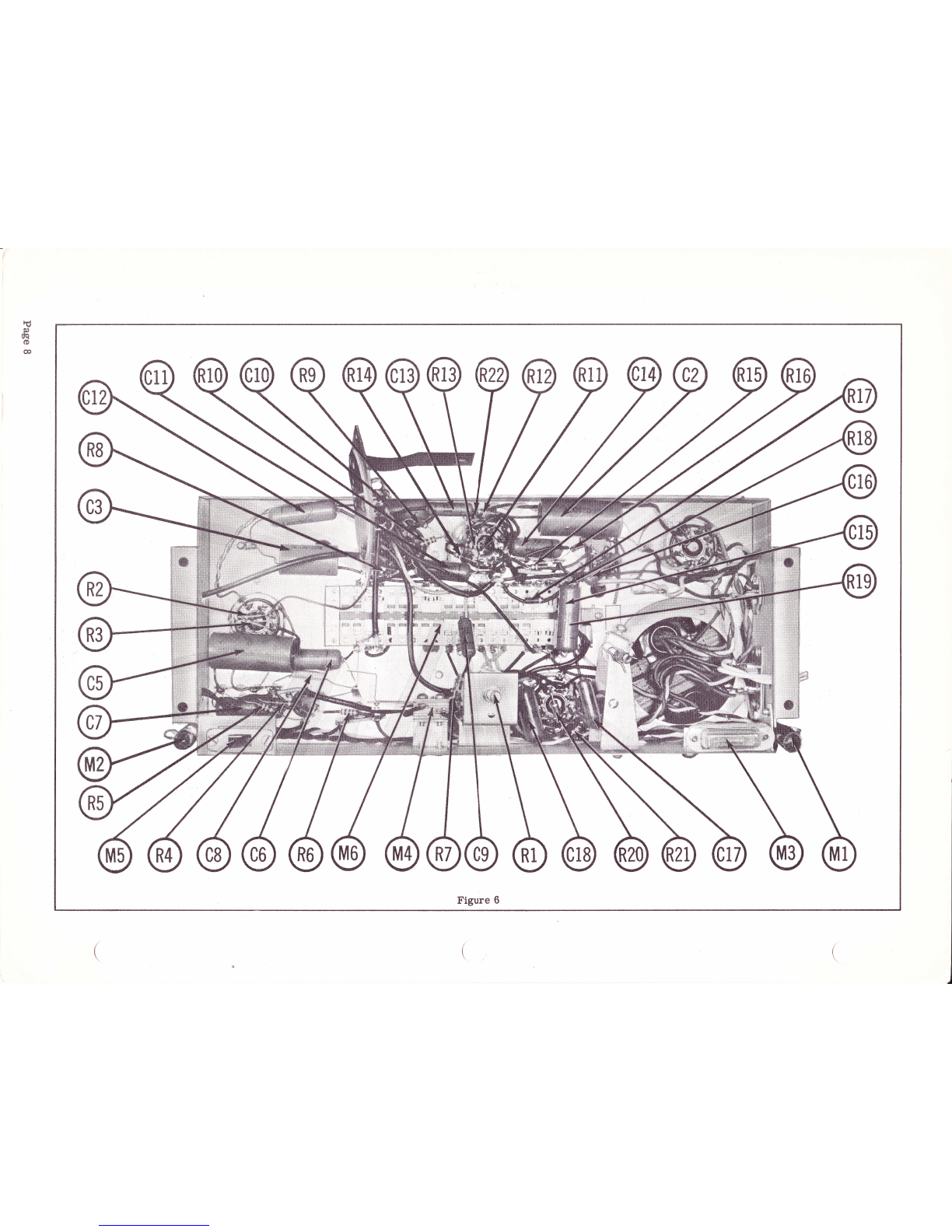
Page 8
=
gtr
lrrfl
FO
leF
GI
o
@
.=
o- t4
o
C\
gr':t
M
o
E-
ul
.t- o
F
{l
M
t-
\tl
hI
o
.s
o- 6t c\I C\t 6t €\t
€
.E
o-
b0
o
"?
AT
{-
bo
o
cr:)
6,i
{- fr{
aM
c\t
€o fr{
a
to
.s
o- M
l.t: M
ro M
o
(o
rf)
M
c\l
oo
o
N
r{
.s
o- bD
o
Fa
X
o
o
rl.)
o
t(?
\ir
{- o
u?
$
{-. k
a
(r)
.s
o- 14
r() M
ro M
{- o
rt)
$
+- o
6T
6l
(\t
.s
a- oo o o o
c
o- oo o oo
o
lttt-
F"
a
CO
t-
l-
(n
(o (o
M
@l(:
l-
CO
F{
(,
II:
X
(0
E
lt)
=c1 tro
o
rq
F.{
z
g
a
frl
a
a
ts
A
frl
o
X
lz1 17
20
9F
HB
OA
AO"i
Xtr>
OO.--
f;H6
s.E€
<zz
}f*ii
*z'-
EH B
a*F
(5 Fr Fr
Fe a
1,4 E
HE H
'.1 B d
"1lt 5
<r;
I
tr
=
u
I
Hr
z-.
o:
h
$e
z4
OE
e,o
<.n
2>
3-
.no)
oo
<i
be
F
o
-
e
.n
o
z
6
llJ
e,
ur
U
z
L
o
llJ
e,
Ellil
l-l
e,
il
o
t
T
J
o'
I
o
tr
o
o
lrj
d.
/4,
:-
f0UOr
I-J
Rg
@
Eg
I
o
F
It
o
!d.
Q8
dl lrl
la
JZ
c-
67
i."-
Pa9
ot
3-3
to,o-
@
ltl
@
-@
9
()
c
I t-il''
@
U
(:
Hil
@
aN
E-
< Itt
.6
P-us
O-
a{!
<
-@
1
o
N
o
5F
*o
=€
:Y
=€
=@
Uffi
Page 9

6SJ 76SJ7 6K6
GT
Figure ?
6J5 6X5GT
MECHANICAL PARTS LIST
Ref .
No. Part
No. Description Ref.
No. Part
No. Description
1
2
3
4
5
6
7
8
I
10
11
t2
13
L4
15
16
t7
18
19
20
2L
22
23
24
25
26
27
28
29
30
30A
TR-101-4119
TR- 101-7031
TR-101-1016A
TR-101-102?
TR-301-1062
TR- 101-102?
TR-301-1065A
TR-301-2199
TR-301-4280
TR-301-4195A
TR-101-4119
TR-301-41964
TR- 101-7010
TR-301-4202
TR-301-4201
TR-101-2033
TR-101-?004
TR- 101-20?3
TR-101-2044
TR-101-2030
TR-101-2065
TR-101-2003
TR-301-2195
TR-301-21?0
TR-301-2184
TR-301-216?A
TR-301-2L84
TR-301-21?9
TR-301-2177A
TR-301-2163
TR-301-21?3
Rewind-Stop - Forward Control
Knob
Phillips Round Head Screw,6-32
Upper Head Shield
. 010" Shield
Head Assembly (cartridge only)
.010" Shield
Lower Head Shield
Capstan Head & Button Assy.
Volume Control Knob
Tone Control Knob
Record-Listen C ontrol Knob
Top Plate
Phillips Head Wood Screw,
r0xLl/4
Indicator Plug Button (red)
Indicator Plug Button (green)
Motor Belt Pulley
Allen Set Screw, 6-32
Spring Retainer
Bakelite Washer
Felt Washer
Fishpaper Washer
Idler Wheel
Rewind Drum Assembly
'!C" Washer
Bakelite Washer
Pressure Roller Assembly
Bakelite Washer
Pressure Roller Shaft
Pressure RoIIer Arm
Capstan Drum Assembly
#9 rro'r Ring
31
32
33
34
35
36
37
38
39
4A
41
42
43
44
45
46
47
48
49
50
51
52
53
54
55
56
57
58
59
60
61
TR-301-21?0
TR-301-2184
TR-301-2180
TR-101-4092
TR-301-2184
TR-301-21?0
TR- 101-2072
TR-301-2184
TR-101-2012
TR-101-2002
TR- 101-2081
TR-101-7005
TR-101-20?9
TR-301-2194
TR-301-2185
TR-301-2184
TR-101-2080
TR-101-2101
TR-101-2094
TR-301-21?0
TR- 101-2012
TR-301-2185
TR-301-2168
TR-101-2065
TR-101-2044
TR-101-2042
TR-101-2038
TR-101-20?r
TR-101-203r
TR-101-2089
TR-301-2182
t'Ct'Washer
Bakelite Washer
No. 6 Self Tapping Screw
Pressure Roller Arm Spring
Bakelite Washer
"Ct'Washer
Spring Retainer
Bakelite Washer
Felt Washer
"O" Ring Belt
BeIt Pulley & Bushing Assy.
Binder Head Machine Screw,
4-40 x 3/16
Tape Disc Assembly
Take-Up Drum Assembly
Bakelite Washer
Bakelite Washer
BeIt PuIIey Lever & Bushing
Assembly
Brake Drive Spring
Brake Assembly
"C" Washer
FeIt Washer
Bakelite Washer
Control Link Assembly
Fishpaper Washer
Bakelite Washer
Idler Lever Spring Clip
Idler Lever Spring
Spring Retainer
Retaining Washer
Idler Lever & Pin Assembly
Base & Bushing Assembl.y
Page I0
t'
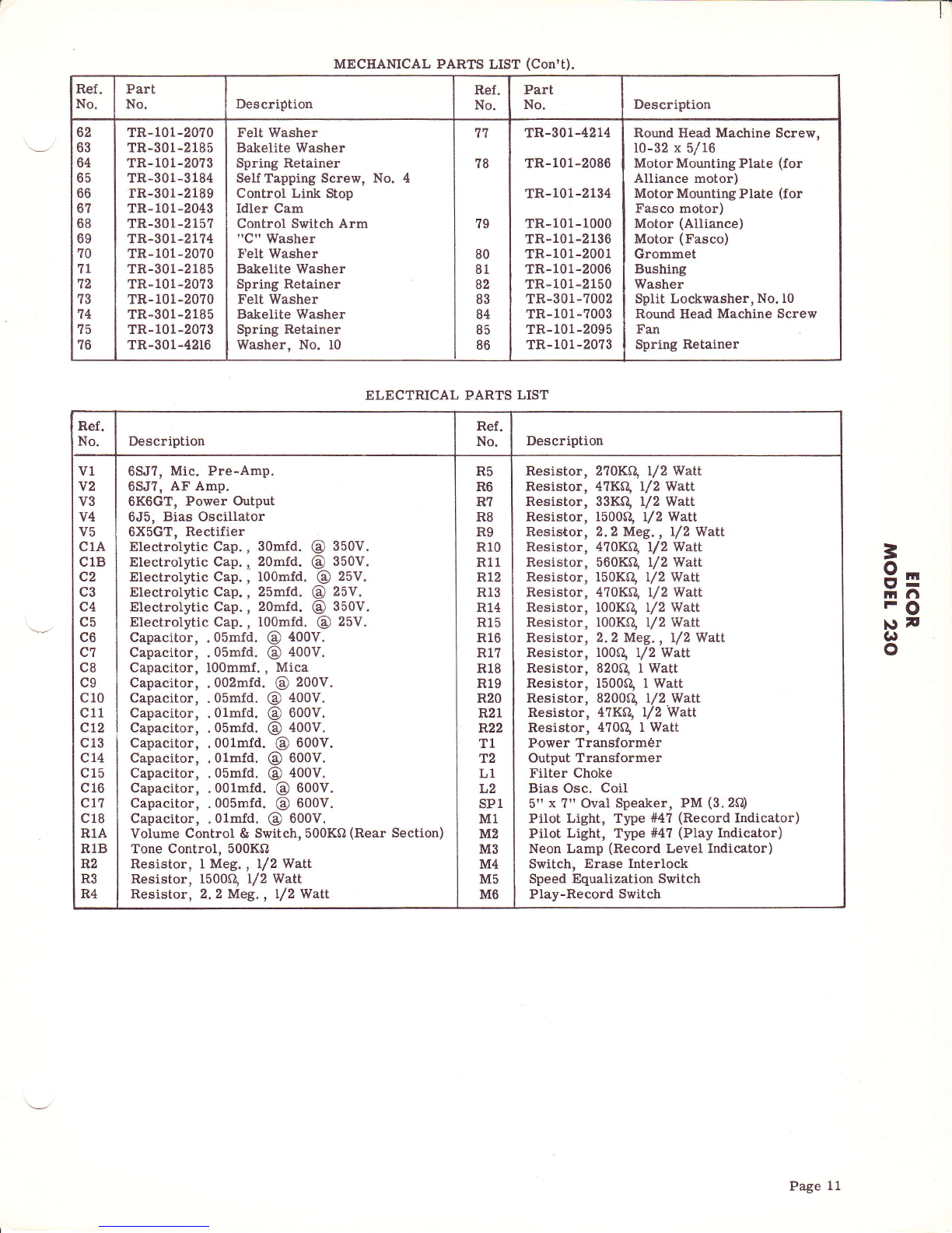
MECHANICAL PARTS LIST (Con't).
Ref .
No. Part
No. Description Ref.
No. Part
No. Description
62
63
64
65
66
6?
68
69
?0
7t
12
?3
14
?5
?6
TR-101-2070
TR-301-2185
TR-101-20?3
TR-301-3184
rR-301-2189
TR-101-2043
TR-301-215?
TR-301-2174
TR-101-2070
TR-301-2185
TR-101-20?3
TR-101-2070
TR-301-2185
TR-101-20?3
TR-301-4216
FeIt Washer
Bakelite Washer
Spring Retainer
SeI{ Tapping Screw, No.
Control Link Stop
Idler Cam
Control Switch Arm
"C" Washer
tr'elt Washer
Bakelite Washer
Spring Retainer
Felt Washer
Bakelite Washer
Spring Retainer
Washer, No. l0
77
?8
?9
80
81
82
83
84
85
86
TR-301-4214
TR-101-2086
TR-101-2134
TR-101-1000
TR-101-2136
TR-101-2001
TR-101-2006
TR-101-2150
TR-301-7002
TR-101-7003
TR-101-2095
TR-101-20?3
Round Ilead Machine Screw,
l0-32 x 5/16
Motor Mounting Plate (for
Alliance motor)
Motor Mounting Plate (for
Fasco motor)
Motor (Alliance)
Motor (Fasco)
Grommet
Bushing
Washer
Split Lockwasher, No. l0
Round Head Machine Screw
Fan
Spring Retainer
ELECTRICAL PARTS LIST
Ref .
No. Description Ref.
No. Description
v1
v2
v3
v4
v5
c1A
c1B
c2
c3
c4
c5
c6
c7
c8
c9
c10
c11
c12
c13
cL4
c15
c16
c1?
c18
R1.A
R18
R2
R3
R4
6SJ?, Mic. Pre-Amp.
6SJ?, AF Amp.
6KOGT, Power Output
6J5, Bias Oscillator
6X5GT, Rectifier
Electrolytic Cap., 30mfd. @ 350V.
Electrolytic Cap., 20mfd. @ 350V.
Electrolytic Cap., lOOmfd. @ 25V.
Electrolytic Cap., 25mfd. @ 25V.
Electrolytic Cap., 20mfd. @ 350V.
Electrolytic Cap., I0Omfd. @ 25V.
Capacitor, .05mfd. @ 400V.
Capacitor, .05mfd. @ 400V.
Capacitor, I00mmf., Mica
Capacitor, .002mfd. @ 200V.
Capacitor, .05mfd. @ 400V.
Capacitor, .01mfd. @ 600V.
Capacitor, .05mfd. @ 400V.
Capacitor, .001mfd. @ 600V.
Capacitor, .01mfd. @ 600V.
Capacitor, .05mfd. @ 400V.
Capacitor, .001mfd. @ 600V.
Capacitor, .005mfd. @ 600V.
Capacitor, .01mfd. @ 600V.
Volume Control & Switch, 500Kfl (Rear Section)
Tone Control, 500KQ
Resistor, I Meg. , l/2 Watt
Resistor, 1500Q l/2 Watt
Resistor, 2.2 Meg. , l/2 Watt
R5
R6
R?
R8
R9
R10
R11
R12
R13
R14
R15
R16
R1?
R18
R19
R20
821
F.22
T1
T2
L1
L2
sP1
M1
M2
M3
M4
M5
M6
Resistor, 2?0Kg I/2 Watt
Resistor, 41KO, I/2 Watt
Resistor, 33KQ t/2 Watt
Resistor, 1500Q /2 Watt
Resistor, 2.2 Meg. , l/2Watt
Resistor, 4?0Kg l/2 Watl
Resistor, 560Kq 12 Watt
Resistor, 150K0, l/2 Watt
Resistor, 4?0Kq 12 Watt
Resistor, l00KA, I/2 Watt
Resistor, l00Kq 12 Walt
Resistor, 2. 2 Meg. , l/2 Watt
Resistor, t00Q /2 Watt
Resistor, 820Q I Watt
Resistor, 1500Q f Watt
Resistor, 8200S1, l/2 V'latt
Resistor, 4?KQ /2 Watt
Resistor, 4?0Q I Watt
Power Transform6r
Output Transformer
Filter Choke
Bias Osc. Coil
5rt x ?ri OvaI Speaker, PM (3. 2f,l)
Pilot Light, Type #4? (Record Indicator)
Pilot Light, Type #4? (Play Indicator)
Neon Lamp (Record Level Indicator)
Switch, Erase Interlock
Speed Equalization Switch
Play-Record Switch
=
9=
rrl.t
FO
\)t
(.)
o
Page 11
Popular Recording Equipment manuals by other brands


Toshiba
Toshiba W602C Service manual

Rami
Rami PRT 666 user manual

Sound Devices
Sound Devices Kashmir MIXPRE-3 II quick start guide

Miditech
Miditech i2 Control-37 black edition user manual

Scanlab
Scanlab RTC 4 Installation and operation

Bulldog Security
Bulldog Security 718 (FPB Installation and owner's guide


