Furman MP-15 User manual

MP-15
MP-20
MP-15Q
MP-20Q
MINIPORTS

General Information
The MP-20 Power Relay provides a 20 amp relay
switched 120 VAC outlet, with a terminal strip that allows
remote control via safe, inexpensive, low voltage Class 2
control wiring. The MP-15 is identical to the MP-20, but is
rated at 15 amps. Both units include an internal 12 VDC
supply. They are housed in a rugged all-metal enclosure
and come equipped with a heavy duty, 10 foot AC cord.
The MP-20 and -15 are listed by NRTL for use in the U.S.
and Canada. The MP-15Q and 20Q are designed for quad
box mounting and have fewer features.
The MP-20 and MP-15 can be used independently
with an RS-1 System Control Panel, or with any other
momentary or maintained-action SPST switch. MiniPorts
can also be used with the Furman PowerLink or ASD-120
MiniPort-20 Wiring Diagram
Figure 1. Connections
for single or multiple Mini-
Port-20 units, Momentary
or Maintained mode.
Figure 2. Connections for
amplier inrush current
reduction, using delayed
turn-on feature. (Turn-off
is not delayed.)
For control from more than
one location, use Momen-
tary Mode and parallel
switch connections.
If using the delay feature
and momentary switches,
rst unit must be in Mo-
mentary Mode, all others
in Maintained Mode. For
control from more than one
location, parallel switch con-
nections to Unit 1.
+12V STATUS REM GND DELAY
MINIPORT #1
MINIPORT #2
+12V STATUS REM GND DELAY
MINIPORT #1
MINIPORT #2
+12V STATUS REM GND DELAY
TO OTHER UNITS TO OTHER UNITS
OPTIONAL LEDS
UNIT 2
UNIT 1
ADD GROUND
FOR > 150' RUNS
OPTIONAL LEDS
UNIT 2
UNIT 1
ADD GROUND
FOR > 150' RUNS
for extra capacity.
With the addition of a PS-RELAC Relay, the MiniPort
can also be used to extend the
capacity of a Furman PS-8R or
PS-PRO Power Sequencer — or
any product with a switched outlet,
such as a receiver/amp controlled
with a wireless remote. When
used in this manner, the MiniPort
is switched on or off when the
outlet into which the PS-REL is
plugged goes on or off.
Momentary vs. Maintained Contact Switching
An on-off switch of either kind may be used to actuate
the MiniPort. Maintained switches, such as most toggle
switches, push-on/push-off button switches, and the
Furman RS-1 locking key switch, stay open until switched,
then stay closed until switched again. Momentary
switches, usually pushbutton types, are normally open and
stay closed only as long as the button is pressed.
Maintained switches are most convenient when there
is only one remote switch location; momentary switches
allow turn-on or turn-off from multiple locations.
MiniPorts come factory-congured for maintained
operation. They may be easily converted to momentary
operation by moving a jumper on the MiniPort’s circuit
board. To do this, rst disconnect the unit from AC power.
Remove the four screws that secure the bottom cover.
In the middle of the circuit board (as viewed from the
bottom of the unit), there are two pairs of terminals, one
labeled “MAINTAINED” and the other “MOMENTARY.”
There is a small black jumper linking the MAINTAINED
terminals. Slide it up and off, and replace it securely over
the MOMENTARY terminals. Reattach the cover.
Maintained Mode
In the simplest configuration, to control a single
MiniPort from a single remote location, connect a
maintained-action SPST switch to the REM and
+12V terminals. Power will be available at the MP-
15/20’s AC outlet when the switch is open, and will be
removed when it is closed. If the cable run is greater
than 150 feet, we recommend that the REM wire be tied
to ground during operation rather than leaving it oating,
using an SPDT switch as shown in Figure 1.
Momentary Mode
In Momentary Mode, the MP-20 and MP-15 have
“memory” — they only need a momentary signal on the
remote terminal to change their state from OFF to ON,
or ON to OFF.
When first plugged in (or after power is lost

and reapplied for any reason) the memory state
is OFF, meaning that no power will be available
at the outlet. It will stay OFF until turned ON by a
momentary connection of the REM terminal to +12V. It will
then stay ON until turned OFF by a second momentary
connection. The ON or OFF state begins on the rising
edge of the signal.
IMPORTANT NOTE REGARDING MOMENTARY
MODE: If multiple MiniPorts are being controlled in
Momentary Mode, power loss to any one of the units will
likely cause its memory to be different than that of the
other units. Not only will this be irritating, it can also be
dangerous, as it may be ON when the others are OFF.
To correct this potential problem (as exists in any simple
momentary switch product), our thoughtful engineers
devised a simple method of holding the switch down (REM
to +12) for at least four seconds. This resets all units to
the OFF condition, and avoids having to disconnect AC
power from all units.
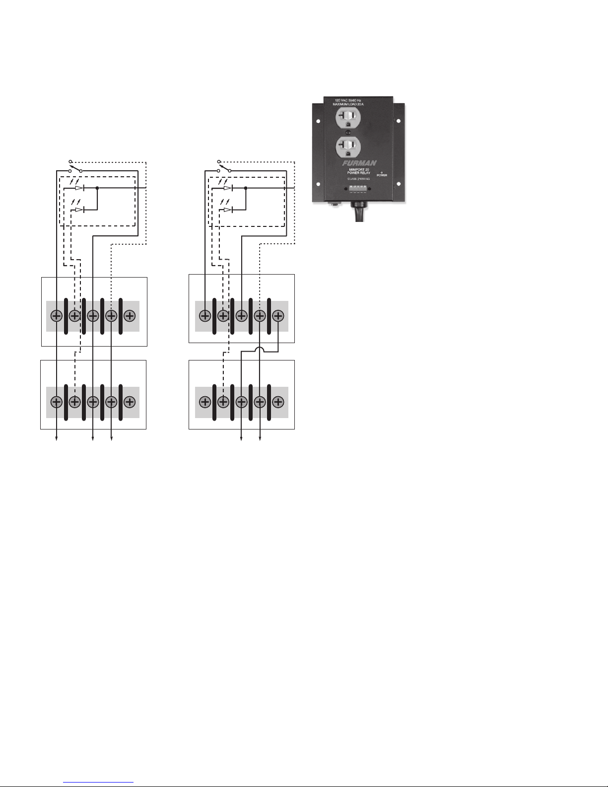
Linking Multiple Units
Multiple MiniPorts may be connected together so that
all are controlled by a single switch closure. All the units
must be set to the same mode depending on the type of
switch or switches to be used (use momentary mode and
momentary switches if more than one switch is required.)
All the units must be paralleled by tying together all the
+12V terminals, all the REM terminals, and all the GND
terminals (see Figure 1).
Multiple MiniPorts may be linked so that they all turn
on simultaneously, as discussed above, or in a delayed
sequence. In a delayed sequence, only the turn-ons are
delayed (all turn-offs occur simultaneously.) This feature is
particularly useful in staggering the turn-on of large power
amps to avoid large inrush currents that might trip the
house circuit breakers. The delay interval is approximately
two to three seconds (the rst unit turns on with the switch
closure, the second in the chain about 3 seconds later,
the third unit 3 seconds after the second, etc.)
The choice of delayed or simultaneous linking is
available regardless of whether maintained or momentary
switching is used. However, if delayed linking is used with
momentary switching, only the rst MiniPort should be set
to momentary mode, and all momentary switches should
be connected in parallel between the rst unit’s +12V and
REM terminals. The second and subsequent MiniPorts
must be left in maintained mode. See Figure 2.
Optional Remote LED Indicator
The MiniPort terminal labeled STATUS is an output
that may be used to illuminate an LED at a remote location
indicating that power is available at the MiniPort’s outlets.
If it is HIGH (+12V relative to the GND terminal), the unit is
ON; if LOW, the unit is OFF. Simply connect the indicator
LED between STATUS and GND (do not use a series
resistor). If multiple units are used, a separate LED must
be used to indicate the status of each. Do not connect the
STATUS terminals of multiple units together.
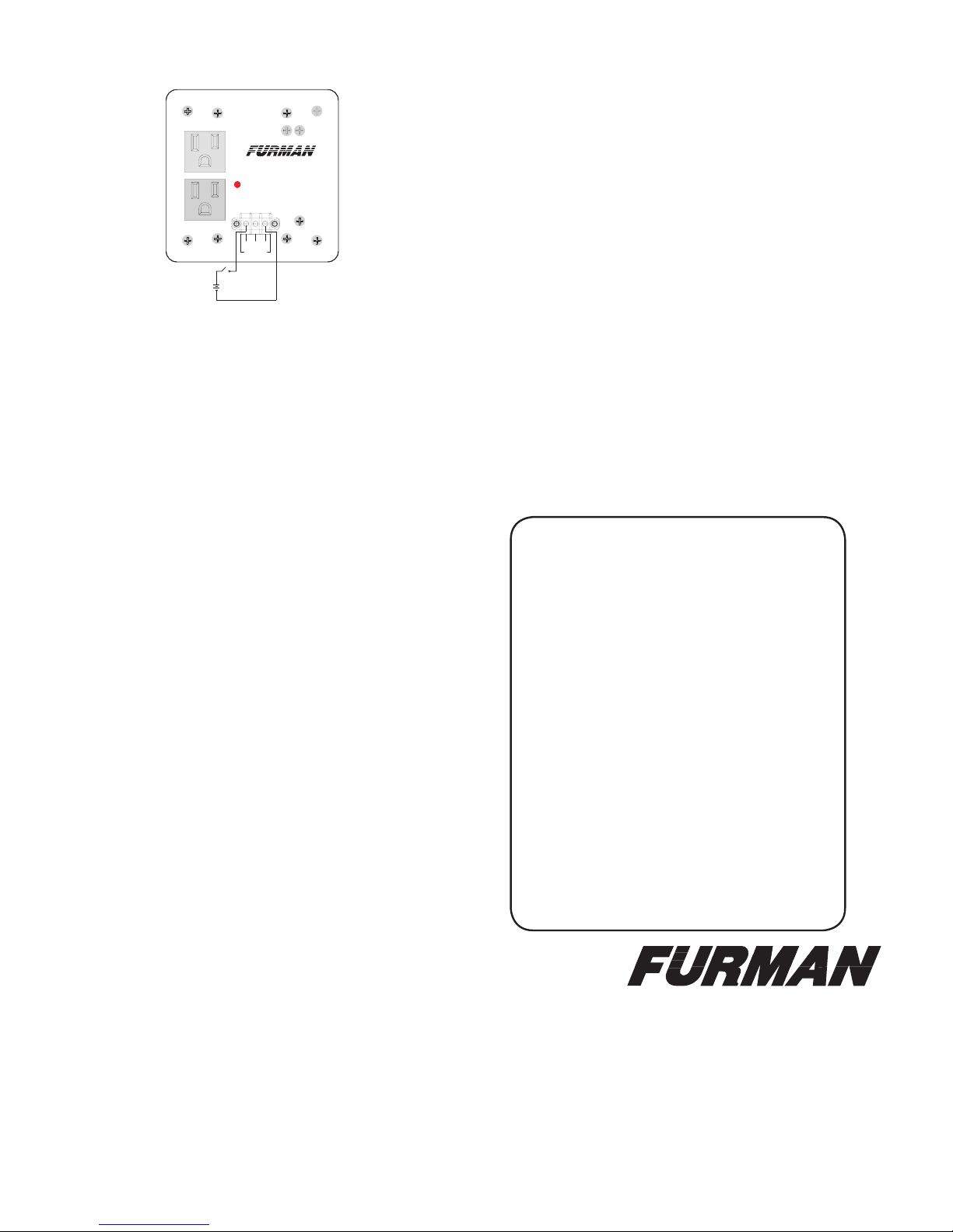
MP-20Q/15Q Quad Box Power Relays
The 20-amp MP-20Q and the MP-15Q (15 amps)
provide a pair of remotely-activated, relay-controlled
outlets, set up for mounting in any standard electrical
quad box, either directly or with a “mud ring” attached.
Due to the space limitations of a quad box, the MiniPort
“Q” models have a smaller feature set than the MP-15
and MP-20.
MiniPort-Q’s have no internal power supply;
a maintained 8-15 VDC supply capable of providing 10
mA is required to turn on the outlets. This can be supplied
by a Furman PowerLink, ASD-120.
(See diagram on the back for more details)
Accessories: RS-1, RS-2
The Furman RS-1 Remote System Control Panel is an
attractively nished key switch designed for use in single-
gang wall mount boxes. From one location it can control
most Furman power products with remote capability. The
RS-2 Remote System Control Panel is identical to the
RS-1 in most respects, but with a momentary function
rather than maintained. The RS-2 is ideal for installations
requiring multiple remote switches.
Three Year Limited Warranty
Furman Sound, LLC., having its principal place of business at
1690 Corporate Circle, Petaluma, CA 94954 (“Manufacturer”) warrants
its MP-15, MP-20, MP-15Q, MP-20Q (the “Product”) as follows:
Manufacturer warrants to the original Purchaser of the Product
that the Product sold hereunder will be free from defects in material
and workmanship for a period of three years from the date of purchase.
The Purchaser of the product is allowed fteen days from the date
of purchase to complete warranty registration by mail or on-line at
the Furman website. If the Product does not conform to this Limited
Warranty during the warranty period (as herein above specied),
Purchaser shall notify Manufacturer in writing of the claimed defects.
If the defects are of such type and nature as to be covered by this
warranty, Manufacturer shall authorize Purchaser to return the Product
to the Furman factory or to an authorized Furman repair location.

with respect to the Product. If any part of this Limited Warranty is
determined to be void or illegal, the remainder shall remain in full
force and effect.
Service
Before returning any equipment for repair, please be sure
that it is adequately packed and cushioned against damage
in shipment, and that it is insured. We suggest that you
save the original packaging and use it to ship the product
for servicing. Also, please enclose a note giving your name,
address, phone number and a description of the problem.
NOTE: All equipment being returned for repair must
have a Return Authorization (RA) Number. To get an RA
Number, please call the Furman Service Department (707-
763-1010 ext.120 or 121) between 8 a.m. and 5 p.m. U.S.
Pacic Time.
Please display your RA Number prominently on the
front of all packages.
Warranty claims should be accompanied by a copy of the original
purchase invoice showing the purchase date; this is not necessary
if the Warranty Registration was completed either via the mailed in
warranty card or on-line website registration. Shipping charges to the
Furman factory or to an authorized repair location must be prepaid by
the Purchaser of the product. Manufacturer shall, at its own expense,
furnish a replacement Product or, at Manufacturer’s option, repair the
defective Product. Return shipping charges back to Purchaser will be
paid by Manufacturer.
THE FOREGOING IS IN LIEU OF ALL OTHER WARRANTIES,
EXPRESS OR IMPLIED, INCLUDING BUT NOT LIMITED TO THE
IMPLIED WARRANTIES OF MERCHANTABILITY AND FITNESS
FOR A PARTICULAR PURPOSE. Manufacturer does not warrant
against damages or defects arising out of improper or abnormal use
of handling of the Product; against defects or damages arising from
improper installation, against defects in products or components
not manufactured by Manufacturer, or against damages resulting
from such non-Manufacturer made products or components. This
warranty shall be cancelable by Manufacturer at its sole discretion if
the product is modied in any way without written authorization from
Furman Sound. This warranty also does not apply to Products upon
which repairs have been affected or attempted by persons other than
pursuant to written authorization by Manufacturer.
THIS WARRANTY IS EXCLUSIVE. The sole and exclusive
obligation of Manufacturer shall be to repair or replace the defective
Product in the manner and for the period provided above. Manufacturer
shall not have any other obligation with respect to the Products or
any part thereof, whether based on contract, tort, strict liability or
otherwise. Under no circumstances, whether based on this Limited
Warranty or otherwise, shall Manufacturer be liable for incidental,
special, or consequential damages. Manufacturer’s employees or
representatives’ ORAL OR OTHER WRITTEN STATEMENTS DO NOT
CONSTITUTE WARRANTIES, shall not be relied upon by Purchaser,
and are not a part of the contract for sale or this limited warranty.
This Limited Warranty states the entire obligation of Manufacturer
NC
POWER
MAX LOAD 15 A
120 VAC 60 Hz
8-15VDC
TO TURN ON
CLASS 2 WIRING
-
POWER RELAY
MINIPORT-15Q
+
NC
POWER
MAX LOAD 20 A
120 VAC 60 Hz
8-15VDC
TO TURN ON
CLASS 2 WIRING
-
POWER RELAY
MINIPORT-20Q
+
Apply 8-15 VDC to turn on
MP-15Q / MP-20Q
Specications
Input Voltage: 120VAC 50/60 HZ
Input / Output Currant:
MP-15, MP-15Q: 15A
MP-20, MP-20Q: 20A
Circuit Breaker/ Fuse:
MP-15: 15A Fuse
MP-20: 20A Thermal
MP-15Q/20Q: None
Dimensions:
MP-15Q/20Q:
4.5” (H) x 4.5”(W) x 1.5”(D)
MP-15/20:
Body: 5.5”(H) x 3.75”(W) x 2”(D)
Baseplate: 5.25” x 5.5”
Weight:
MP-15/20: 3.50 lbs.
MP-15Q/20Q: 1 lb
050804-F
Furman Sound, LLC.
1690 Corporate Circle
Petaluma, California 94954-6919 USA
Phone: 707-763-1010
Fax: 707-763-1310
Web: www.furmansound.com
E-mail: [email protected]
Made in China
This manual suits for next models
3
Table of contents
Other Furman Recording Equipment manuals

Furman
Furman PWRLINK User manual

Furman
Furman PS-8R II User manual

Furman
Furman PS-PRO E II User manual

Furman
Furman PS-PRO User manual

Furman
Furman CN-3600SE User manual

Furman
Furman MP-30 User manual

Furman
Furman RR-131 User manual

Furman
Furman PS-PRO User manual

Furman
Furman RackRider RR-131 User manual

Furman
Furman PS8 R II User manual