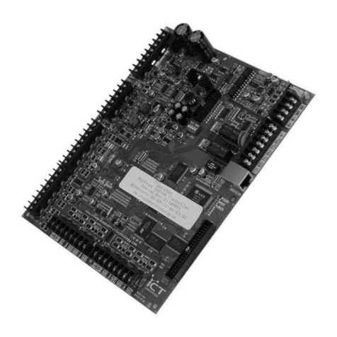
EINBREW 3V2P User manual

EINBREW.COM
EINBREW 3V2P USER INSTRUCTIONS
V1.1.1 285 © ACKSEN LTD 2019
1

EINBREW.COM
EINBREW 3V2P USER INSTRUCTIONS
V1.1.1 285 © ACKSEN LTD 2019
2
INTRODUCTION
Congratulations on your investment in an EINBREW 3V2P electric brewing controller. Our precise
temperature control, automatic mash steps, Boil Detect and hop insertion alarms means that you
can focus on what you really want –making great beer with your home brewery.
There’s nothing as satisfying as putting together your own brewery, however dealing with complex
electrical and temperature control can be concerning –not only making sure everything works the
way you want, but safely too! EINBREW 3V2P takes away those concerns with a flexible,
configurable and industrial-grade control system –all expertly engineered into an easy to install
package. Just plug in your heaters and pumps, no electrician or electrical experience needed!
We’ll work with your existing heaters and pumps – no need to purchase additional, expensive
equipment. Our control will help you make a great batch of sweet wort every time, and give you the
repeatability you want.
Our temperature control will automatically adjust itself to your system’s requirements – you don’t
need to be a chemical engineer to get brewing.
These user instructions will help you get the best out of your EINBREW 3V2P system and allow you
to use it safely, and we recommend you read through them fully before installation and starting your
brew day!
For further help, search ‘EINBREW’ or ‘3V2P’ on YouTube.com

EINBREW.COM
EINBREW 3V2P USER INSTRUCTIONS
V1.1.1 285 © ACKSEN LTD 2019
3
CONTENTS
Introduction ....................................................................................................................................................2
Contents..........................................................................................................................................................3
Safety Information ..........................................................................................................................................5
Technical Specifications..................................................................................................................................6
Components and Accessories.........................................................................................................................7
Brewing System Requirements.......................................................................................................................8
Getting Started .............................................................................................................................................10
Brewing System Integration..........................................................................................................................11
Installing C20 Plug to Heating Element Leads...........................................................................................11
Installing C13 Plug to Pump Leads ............................................................................................................11
Installing Temperature Probes to Brewing Vessels ..................................................................................12
Extending EINBREW 3V2P C20 Power Lead..............................................................................................13
Replacing user-replaceable fuses .............................................................................................................13
Drilling Holes in Stainless Steel Vessels for Heating Elements and/or Temperature Probes ...................13
Mounting the Control Panel .....................................................................................................................14
Basic System Testing.................................................................................................................................15
Control Panel ................................................................................................................................................16
Configuration Menu......................................................................................................................................21
Preparing for Brewing...................................................................................................................................23
Entering your Recipe.................................................................................................................................23
Setting Preheat/Mash In Stage.................................................................................................................23
Setting Mashing Stage ..............................................................................................................................24
Setting Boiling Stage/Automatic Boil Detect ............................................................................................24
Setting Hop Insertions ..............................................................................................................................25
Setting Cooling Stage ................................................................................................................................25
Brewing Wort................................................................................................................................................26
Pre-Heat/Mashing In Stage.......................................................................................................................26
Mashing Stage...........................................................................................................................................26
Boiling Stage / Automatic Boil Detect.......................................................................................................26

EINBREW.COM
EINBREW 3V2P USER INSTRUCTIONS
V1.1.1 285 © ACKSEN LTD 2019
4
Cooling Stage ............................................................................................................................................27
Brew Complete! ........................................................................................................................................27
Cleaning ....................................................................................................................................................27
Troubleshooting............................................................................................................................................29
Maintenance Menu ......................................................................................................................................32
Warranty.......................................................................................................................................................35
Maintenance.................................................................................................................................................35
Returning EINBREW 3V2P for repair.............................................................................................................35
WEEE Regulations .........................................................................................................................................36

EINBREW.COM
EINBREW 3V2P USER INSTRUCTIONS
V1.1.1 285 © ACKSEN LTD 2019
5
SAFETY INFORMATION
•Please inspect your EINBREW 3V2P system and accessories for damage when you receive it. If
there is any damage, please do not use the system and contact your supplier or Support for
assistance.
•Do not operate the system if the power leads show any signs of damage or wear.
•If you need to clean the surface of your EINBREW 3V2P system, please ensure that it is fully
disconnected from the mains supply beforehand. We recommend removing the plug from the
socket to ensure disconnection. Use only a damp cloth and do not allow liquid to come in
contact with EINBREW 3V2P, and ensure the vessel is dry before reconnecting the electricity
supply.
•The EINBREW 3V2P MUST be used with a RCD/GFCI/RCBO device. Ensure that you test it prior
to every use.
•Ensure that the supplied power lead is fully unwound during use. If using any extension leads,
ensure that they are fully unwound and have a 15A current capacity when unwound.
•EINBREW 3V2P is not to be used by children or vulnerable adults, or around pets. Please ensure
that the device is only used with adequate supervision to ensure safety.
•EINBREW 3V2P does not contain any internal user serviceable parts, and should not be
disassembled or repairs attempted. Please contact your supplier or Support for any assistance
required.
•Ensure that EINBREW 3V2P is positioned as far away as possible from liquids and vapours being
used in the brewing process or condensate paths that may form –its enclosure is not water-
tight.
•You must manually control the Pumps during brewing. This is especially important if you are
using a RIMS system, as it can be dangerous to operate the heater without the pump and water
circulation.
•Do not operate your brewery or EINBREW 3V2P unless you are certain it has been correctly and
safely setup. You may need to refer to a qualified/licensed electrician to achieve this.
•DO NOT USE THIS PRODUCT AS AN ISOLATION DEVICE, TO ISOLATE PUMPS, ELEMENTS OR ANY
EQUIPMENT.

EINBREW.COM
EINBREW 3V2P USER INSTRUCTIONS
V1.1.1 285 © ACKSEN LTD 2019
6
TECHNICAL SPECIFICATIONS
Feature
Product Dimensions
300mm x 260mm x 85mm
Power Supply Input
220Vac/230Vac, 50Hz, 15Amax
Control Precision
0.1C (or 0.1F in Fahrenheit mode)
Temperature Measurement Accuracy
0.1C (or 0.1F in Fahrenheit mode)
Heating Elements Supported
2, (Hot Liquor Tank and Boil Kettle), consecutive use (15A
Maximum each), IEC C19 Sockets
Pumps Supported
2, 2.9A Max (1.4A each), C14 Sockets (man & auto control)
Product Weight
3kg
Environmental
IP43, keep dry, splash proof fascia.
Brewing Vessels Supported
3, for Hot Liquor Tank, Mash Tun and Boil Kettle
Temperature Monitoring
YES, 3 PT100 sensors (Hot Liquor Tank, Mash Tun and Boil
Kettle)
PCB fuses
2, 3A, 20mm x 5mm
Power fuses
2, 15A, 32mm x 6.3mm
HERMS Support
YES
RIMS Support
YES
Audible Alarms
YES
Visible Alarms
YES
Audible Cooling Alarm
YES
Visible Cooling Alarm
YES
Automatic Timer
YES
Recipe Stored in Memory
YES, one recipe.
Programmable Recipe
YES, 9 programmable mash stages
Automatic Boil Detect
YES
Microprocessor Control
YES
Hop Insertions Alarms
YES, 9 programmable insertion alarms
Ergonomic Design
YES
Limited Lifetime Warranty
YES
Product Compliance
CE and LVD Compliant
Country of Manufacture
United Kingdom

EINBREW.COM
EINBREW 3V2P USER INSTRUCTIONS
V1.1.1 285 © ACKSEN LTD 2019
7
COMPONENTS AND ACCESSORIES
Your EINBREW 3V2P system will come shipped with the following components. When you unpack
please ensure you check everything is there, and if any parts are missing please contact your supplier
or Support immediately.
1) 1 x EINBREW 3V2P Electric Brewery Controller
2) 1 x Power Lead, IEC C20 Socket, 2m lead.
3) 3 x Temperature Sensor, ¼” BSPP thread, 80mm length, with 3m lead.
4) 2 x Heater output plug, C19.
5) 2 x Pump output plug, C13.
6) 1 x User Instructions (detailed).
7) 1 x Quick Start Guide.

EINBREW.COM
EINBREW 3V2P USER INSTRUCTIONS
V1.1.1 285 © ACKSEN LTD 2019
8
BREWING SYSTEM REQUIREMENTS
We aim for EINBREW 3V2P to take care of electrical control for you, leaving you to concentrate on
designing and building your brewing system!
Constructing your own Electric Brewery is beyond the scope of these user instructions, and there are
a number of great guides out there that’ll help you achieve this. There are also a number of
performance and safety issues to consider when specifying and putting together your brewery.
However, for EINBREW 3V2P to work effectively, there are some areas to consider.
•Your heating elements must be appropriately sized for the amount of wort you’re trying to
heat/produce, whilst meeting the maximum EINBREW 3V2P power restrictions. If the heating
elements are too small, it may take a long time to increase the temperature of the wort as you
go through the brewing process, especially when boiling. In the worst case, you may be unable
to maintain your target temperature at all due to losses. You can also improve system
performance by ensuring that you keep a lid on your vessels when brewing, and insulating the
vessels. Elements that are too large may result in scorched wort, or considerable temperature
overshoot and oscillation during heating.
•EINBREW 3V2P supports one heating element for the Hot Liquor Tank, and one heating element
in the Boil Kettle, each up to 15A. This can only be used consecutively, not concurrently. For the
Hot Liquor Tank, the element can be directly in the vessel, or you can use an external heating
element through which wort is pumped around.
•Your system pump must be sufficiently powerful for the task –importantly, if using RIMS the
water flow must be able to remove heat from the in-circuit heating element at a sufficient rate,
or you may encounter issues where the water is e.g. boiling at the heater itself and much cooler
elsewhere. The pumps must also be rated for use at the operating temperature –it is worth
noting that many pumps will not operate correctly at 100C (boiling) due to cavitation. You
ideally want the temperature throughout the system to be as equal as possible, helping to
reduce temperature overshoot and oscillation. In the worst case, you could encounter
equipment damage or scorched wort. Similarly, the pump must be powerful enough to
continuously recirculate the wort through your mash without sticking, if relevant. The amount of
flow required can also vary depending on the type of grain and crush quality used.
•It is important that you do use pumps in your system where feasible, as if the volume of water is
not well mixed, the accuracy and quality of the control system will degrade.
•Ensure that your system interconnector pipes are of sufficient diameter to let through enough
flow, and is rated for use at the operating temperature. Make sure you test the system with the
pumps running and cold water after installation, to ensure there’s no leaks – these could be
dangerous when working with heated wort!
•Ensure that you have added sufficient filtering to the pump inlet –otherwise, you may encounter
clogging or flow restrictions after adding grain due to debris or grain in the fluid path/circuit. The
same applies if you intend to e.g. recirculate after hops have been added.

EINBREW.COM
EINBREW 3V2P USER INSTRUCTIONS
V1.1.1 285 © ACKSEN LTD 2019
9
•EINBREW 3V2P supports up to two pumps up to 2.9A, which you manually activate via the
Control Panel. Typically, you’d use a pump for recirculation between the Hot Liquor Tank and
the Mash Tun, and sometimes also used with an external heating element. The 2nd pump can be
used for moving wort between the Mash Kettle and the Boil Kettle, or vessel recirculation.
•Ensure that the 3 temperature probes provided with EINBREW 3V2P are adequately fitted. For
example, it is important that you install the Mash Tun temperature probe near the point where
heated liquid is fed back into the Mash Tun, and not for example after it has circulated through
the mash bed or at the pump inlet. Not doing so will result in issues such as temperature
overshoot and oscillation, or in the worst-case equipment damage or scorched wort. If you are
using an internal heating element, do not place the temperature probe right beside it.
•EINBREW 3V2P provides precision temperature probes and control systems, and should provide
excellent temperature control over a wide range of brewery configurations. However, its
performance is ultimately down to the equipment you’ve specified. It is normal that the
maintained temperature will fluctuate and you may see slight temperature overshoot when
brewing. This can be exacerbated by issues such as insufficient pump flow, too large/too small
heating element.
•Additional safety equipment such as installing a float switch to prevent your pump running dry
and the elements operating without water added can be worthwhile additions.
•Unless you’re building an off-the-shelf brewery kit, be prepared to experiment and improve your
brewery as you go! It’s not unusual for systems to require tweaking after first being assembled.

EINBREW.COM
EINBREW 3V2P USER INSTRUCTIONS
V1.1.1 285 © ACKSEN LTD 2019
10
GETTING STARTED
We know you’re eager to get on with making some beer, so the first thing to do is get your EINBREW
3V2P system installed with your brewing setup!
Once you’ve checked you’ve got everything, work out where you’re going to install your EINBREW
3V2P controller. Everyone’s brewery is different; however, you should make sure that it is situated
far enough away from your brewing vessels that there won’t be any liquid splashed on the
controller, or any danger of steam condensing and dripping on the controller for above.
Please also make sure that the inlet power cable for EINBREW 3V2P, the outlet power cables for the
heating elements and pumps, and the temperature sensor cables will reach without being taut or
presenting a trip hazard.
EINBREW 3V2P should be connected to an electric outlet suitable for the total electrical load you
wish to drive, controller + heaters + pumps. The supply MUST be protected by an RCD/GFCI/RCBO
device, for your safety –please test the RCD/GFCI/RCBO device before use, using the built-in test
function.
IF YOU DO NOT UNDERSTAND THE ABOVE STATEMENT, PLEASE CONSULT A LOCAL EXPERT.
Once that’s done you’re ready to turn on! Move the power switch to the ON position and EINBREW
3V2P will power on, running through a short self-test of the onboard displays, indicators and alarm
buzzer before starting. This will only take a few seconds.
When operational, EINBREW 3V2P will display the readings from the 3 temperature sensors on its
displays and you can begin configuring and testing the system.

EINBREW.COM
EINBREW 3V2P USER INSTRUCTIONS
V1.1.1 285 © ACKSEN LTD 2019
11
BREWING SYSTEM INTEGRATION
We know you’re eager to get on with making some beer, so the first thing to do is get your EINBREW
3V2P system installed with your brewing setup!
Installing C20 Plug to Heating Element Leads
The EINBREW 3V2P connects to your heating elements using C19 power sockets. To interface with
these, you need to install C20 plugs onto the power leads for each of your heating elements. If you
are unsure of any aspects of how to undertake this task, please contact a competent person (e.g.
qualified and certified Electrician) for advice and assistance. Miswiring a plug can be fatal. FIRST
ENSURE YOUR POWER LEAD IS NOT CONNECTED TO THE POWER SUPPLY. Generally resistive heating
elements are unpolarised, so live and neutral can be swapped.
Remove the screws holding together the spare C20 plug that has been supplied with your system.
Leave these carefully to one side.
Once you’ve done that, you’ll note that there are screw terminals for Live, Neutral and Earth –along
with a retaining clamp for the power cable to be inserted, to ensure that it cannot be taken out later.
Unscrew the retaining clamp to allow you to feed in the power cable. Earth to the centre, Neutral to
the left and Live to the right.
Strip back the Live, Neutral and Earth conductors to allow you to fit the exposed conductors into the
appropriate screw terminals. You may need to shorten one or more of the conductors for a good fit.
For safety, ensure that you only strip enough of the protective sheath to allow insertion of the
relevant conductor into each of the screw terminals –no more.
Screw each of the terminals down firmly to ensure that the conductor cannot move and is securely
in place, then screw down the retaining clamp for the power cable such that it is also secure.
Finally, reassemble the C20 plug using the screws from earlier, firmly screwing the plug back
together.
To test, ensure that EINBREW 3V2P is turned off, then insert the assembled C20 plug with attached
power cable into the C19 receptacle. Ensure that the vessel the heating element is fitted to has
enough water added to at least cover the element sufficiently. Turn on the EINBREW 3V2P system,
and utilise the control system to energise the heating element. You should note that the water will
increase in temperature accordingly.
Installing C13 Plug to Pump Leads
The EINBREW 3V2P connects to your pumps using C14 power sockets. To interface with these, you
need to install C13 plugs onto the power leads for each of your pumps. If you are unsure of any
aspects of how to undertake this task, please contact a competent person (e.g. qualified and
certified Electrician) for advice and assistance. Miswiring a plug can be fatal. FIRST ENSURE YOUR
POWER LEAD IS NOT CONNECTED TO THE POWER SUPPLY.

EINBREW.COM
EINBREW 3V2P USER INSTRUCTIONS
V1.1.1 285 © ACKSEN LTD 2019
12
Remove the screws holding together the spare C13 plug that has been supplied with your system.
Leave these carefully to one side.
Once you’ve done that, you’ll note that there are screw terminals for Live, Neutral and Earth – along
with a retaining clamp for the power cable to be inserted, to ensure that it cannot be taken out later.
Unscrew the retaining clamp to allow you to feed in the power cable.
Strip back the Live, Neutral and Earth conductors to allow you to fit the exposed conductors into the
appropriate screw terminals. You may need to shorten one or more of the conductors for a good fit.
For safety, ensure that you only strip enough of the protective sheath to allow insertion of the
relevant conductor into each of the screw terminals –no more. Earth to the centre, Neutral to the
left and Live to the right.
Screw each of the terminals down firmly to ensure that the conductor cannot move and is securely
in place, then screw down the retaining clamp for the power cable such that it is also secure.
Finally, reassemble the C13 plug using the screws from earlier, firmly screwing the plug back
together.
To test, ensure that EINBREW 3V2P is turned off, then insert the assembled C13 plug with attached
power cable into the C14 receptacle. Ensure that the system the pump is fitted to has enough water
added to operate the pump sufficiently –this is especially important if the pump will be damaged if
run dry, and does not have run dry protection. Turn on the EINBREW 3V2P system, and utilise the
relevant pump button to activate it. You should observe that the pump will activate.
Installing Temperature Probes to Brewing Vessels
The EINBREW 3V2P comes supplied with 3 Temperature Probes to allow you to monitor and control
your system. These will typically be PT100 probes depending on the type of system you have
purchased; however, installation and operation is identical.
To fit the probes into each vessel, firstly consider where you are going to place each probe. The
ideal placement will vary depending on factors like the type of heating system you have chosen to
use, along with other factors. Generally, the temperature probe is positioned near the bottom of a
vessel, about 40/45mm from the base and at 90 degrees to the heating element. The sensors are
80mm in length and have a ¼” BSPP thread, which requires a 13/14mm hole in the vessel.
Hot Liquor Tank (HLT) –if you are using a HERMS system, then the HLT should have a heating
element fitted. It is important not to install the temperature sensor too near the heating element,
as this can produce readings which are artificially high and prevent the control system from
operating correctly. A good place may be close to the heat exchanger coil that is used to supply heat
to the Mash Tun. If you are using a RIMS system, the temperature sensor should be placed in the
area of the RIMS outlet into the vessel, in order to monitor the output temperature of that system.
Mash Tun (MT) –Generally the Mash Tun will be indirectly heated by the HLT. As such, the
temperature sensor should probably be placed around bottom inlet for the circulation pump, if
utilised. If a RIMS system is being used to heat the MT, then fit the sensor around the heated water
inlet.

EINBREW.COM
EINBREW 3V2P USER INSTRUCTIONS
V1.1.1 285 © ACKSEN LTD 2019
13
Boil Kettle (BK) –normally the Boil Kettle will have a direct heating element fitted. It is important
not to install the temperature sensor too near the heating element, as this can produce readings
which are artificially high and prevent the control system from operating correctly. Around the
middle of the vessel may be a useful place to site the probe.
Extending EINBREW 3V2P C20 Power Lead
The EINBREW 3V2P comes supplied with a 2m power lead. However, you may find this is insufficient
for your purposes. If this is the case, please extend the cable using a suitable extension cord, or
purchase a longer power lead.
Please note any replacement/extension must be capable of handling 15A of current. If using a
wound extension cord, please ensure that it is fully unwound before use to allow it to handle its
maximum rated capacity. Not doing so will reduce the current capacity of the cable and may result
in fire or death.
Replacing user-replaceable fuses
There are two user-replaceable fuse receptacles mounted on the base of the enclosure. If you
believe that these fuses have blown, these can be replaced. Please ensure to replenish them with an
equivalent specification of fuse.
To replace, first ensure that you have turned off EINBREW 3V2P by disconnecting it at the plug. This
will ensure the system is isolated. Then use a screwdriver to access the fuse compartments, and
replace the damaged fuses. If capable, you may wish to use a e.g. multimeter to test if the fuse(s)
are actually damaged or not, as the fault may lie elsewhere.
Insert the new fuse(s) and screw in the fuse compartment again. Then reconnect the system to
mains electrical supply, and test the system to ensure that it operates correctly.
Drilling Holes in Stainless Steel Vessels for Heating Elements
and/or Temperature Probes
Depending on which vessels you are using in your system, you may already have holes pre-drilled for
heating elements and water pump inlet/outlets –this makes things very convenient as you can
simply use those for installation, as long as they’re in the right place!
However, if you are building a system without any of this work carried out, you will have to
undertake the work yourself.
Firstly, confirm that you have appropriate drill bits (or hole saws, etc) and drill (available speed, etc)
for the job of creating these holes. You will likely require special drill bits, and depending on the
grade and thickness of the stainless steel, you may require non-standard and/or higher speed drill

EINBREW.COM
EINBREW 3V2P USER INSTRUCTIONS
V1.1.1 285 © ACKSEN LTD 2019
14
drivers also. If you do not have experience in this work, you would be advised to contract a
specialist metal worker to help, as it can be easy to damage or cosmetically mark your vessels.
Next, mark out the holes in the design to ensure that placement of the new equipment is correct.
Then create the hole. After the metal has cooled down afterwards, fit the elements and probes as
necessary. Ensure that the vessels are well cleaned afterwards to ensure that no metal shavings or
dust get into the brewing system during use.
Mounting the Control Panel
The panel must be mounted vertically. There are mounting holes in tabs on the corners of the
enclosure, these are used to mount the panel. During use the rear of the panel can get hot, this is
normal. It is vital that a gap be left between the rear and the mounting surface, to allow airflow, the
outward dimples are to facilitate this. It is also vital that the mounting surface can withstand
temperatures of up to 50C. Ensure that you do not over-tighten the 4 mounting screws and bend the
tabs, the tabs should remain vertical like the rear of the control panel.

EINBREW.COM
EINBREW 3V2P USER INSTRUCTIONS
V1.1.1 285 © ACKSEN LTD 2019
15
Basic System Testing
Once you’ve installed all your heating elements, pumps and temperature probes – it’s time to test
everything out before properly brewing wort!
Connect up everything to EINBREW 3V2P, and add some water into each of the 3 vessels. The water
level will need to be sufficient to cover the elements and to correctly fill the circulation system(s).
The first thing to try is to activate each pump in turn. Ensure the correct valves are in the correct
orientation open/closed as required. Press the P1 and P2 buttons on the interface respectively to
drive each pump in turn, if you have enabled Pump Vent, then the pump will pulse on and off several
times before remaining on. Confirm that it is operating correctly, and flowing well. Also ensure that
there are no leaks coming from any pipework! If there are any leaks that look as if they may contact
with electrical connections, disconnect the power to your system immediately.
Once the circulation system seems to be working OK, activate the Pre-Heat/Mash In stage and
confirm that the heating system/heat exchanger is warming the HLT and/or MT as expected. It will
take time for the temperature to increase, so do not expect an instant ramp to your set
temperature. Take care to look for any leaks as time goes on. You may find that you need to tighten
connectors, add washers, etc. before everything is completely watertight.
Next move onto the Boil stage, and test the heater in the Boil Kettle. Again, you should see the
temperature rising in the vessel when activated.
When testing, make sure that the temperature probes have been connected to each vessel correctly
–for example, that the Boil Kettle probe has not been connected to the Hot Liquor Tun, or similar.
Also make sure that the heating elements and pumps turn on appropriately, and they haven’t been
connected to the wrong sockets.
After you’ve carried out the basic tests, dispose of all the water from the system in case there is any
loose debris or other material present. Then you’re ready to brew for real!

EINBREW.COM
EINBREW 3V2P USER INSTRUCTIONS
V1.1.1 285 © ACKSEN LTD 2019
16
CONTROL PANEL
Before beginning to make your brew, let’s go through the main control panel. EINBREW 3V2P is
designed to be very similar to a traditional brewery control system, with separate temperature
monitoring for each vessel in the system.
Our diagram of the front panel below illustrates some of the options available.
Control Section
Explanation
Timer
Allows you to set the time for up to 9 (nine) Mash Steps and the Boil duration,
along with 9 Hop Insertion times and alarms. The Up/Down buttons will allow
you to increase/decrease the presently displayed time. You can also press
and hold the buttons to go to the highest/lowest value (or OFF if available).
The Time displayed will depend on the particular Stage/Step you’re in. The
red indicator for this section will be lit when the Timer is active.
Any changes made will be automatically stored in the 3V2P memory.

EINBREW.COM
EINBREW 3V2P USER INSTRUCTIONS
V1.1.1 285 © ACKSEN LTD 2019
17
Control Section
Explanation
HLT
Hot Liquor Tank
Displays the Measured Temperature on the top half, and the Set Temperature
on the bottom half of the display. The Up/Down buttons will allow you to
increment and decrement the presently displayed set temperature. This
temperature is used for preheating, so only a single temperature will be
displayed/set.
The Green indicator will be lit when the Preheat stage involving the HLT is
active, changed using the Select button. The Red indicator will be lit when
the stage is running and the heater has been turned on.
Any changes made will be automatically remembered.
MT
Mash Tun
When the Mash Stage is inactive, the display automatically alternates
between:
1) Displaying the Measured Temperature on the top half of the display,
and the Set Temperature for the presently selected Mash Step on the
bottom half.
2) Display the Mash Step on the top half (St 1 to St 9) of the display, and
the Set Temperature for each Mash Step 1-9 on the bottom half.
When the Mash Stage is active, the display shows the Measured Temperature
on the top half of the display, and the Set Temperature for the presently
selected Mash Step on the bottom half. The present Mash Step time will be
displayed on the bottom half of the Timer display (St 1 to St 9) and can be
adjusted there.
The Up/Down buttons will allow you to increment and decrement the
presently displayed set temperature. You can also press and hold the buttons
to go to the highest/lowest value, or OFF if available.
To switch between the different Mash Step timings, when the MT stage is
active, press the Set button. The display will go through Mash Step 1 to Mash
Step 9, and back to Mash Step 1 each time Set is pressed. If you don’t want to
use a particular Mash Step, set the time for the Step to be OFF (go to 0
minutes, then press Down again so the display changes to OFF). Please note
that Mash Steps set to 0 minutes will change the set temperature for the
brew accordingly when they’re triggered, but will not run for any time when
the set temperature is met.
The Green indicator will be lit when the Mash Stage is active, changed using
the Select button. The Red indicator will be lit when the stage is running and
the heater has been turned on.
Any changes made will be automatically remembered.

EINBREW.COM
EINBREW 3V2P USER INSTRUCTIONS
V1.1.1 285 © ACKSEN LTD 2019
18
Control Section
Explanation
BK
Boil Kettle
Displays the Measured Temperature on the top half of the display, and the
Boil Power Percentage on the bottom half (e.g. “P50” = 50% Power). This
determines how much power is put into the system after boil has been
detected, and allows you to control how vigorous the boil will be. The
Up/Down buttons will allow you to increment and decrement the presently
displayed Boil Power Percentage in 10% steps.
The present Boil time will be displayed on the bottom half of the Timer
display and can be adjusted there.
To switch between the different Hop Insertion timings, when the BK stage is
active, press the Set button. The display will go through Hop Insertion 1 to
Hop Insertion 9 on the bottom half of the timer display above (HOP1 to
HOP9), and go back around to Boil Power Percentage, each time Set is
pressed. If you don’t want to trigger a particular hop insertion, set the time
to be OFF (go to 0 minutes, then press Down again so the display changes to
OFF). Please note that Hop Insertions set to 0 minutes will be triggered
immediately as the Boil stage starts.
The Green indicator will be lit when the Boil Stage is active, changed using the
Select button. The Red indicator will be lit when the stage is running and the
heater has been turned on.
Any changes made will be automatically remembered.
P1
Pump 1
Press the P1 button to turn Pump 1 on and off. The Pump will automatically
go through a Pump Ventilation cycle each time it is turned on –you can set
this in the Configuration Menu.The button must be held down for
approximately a second before it will activate.
The red indicator will show if the pump is presently turned on or off.
Please note that the pump is manually controlled using this button –it will
not generally be switched on or off automatically. The exceptions are if you
press and hold the Stop button or reach the end of the Cooling phase, all
pumps will be turned off. Additionally, it will be temporarily turned off during
Grain Rest intervals if it is selected as the Mashing Pump.
If Pump Exclusion is turned on, activating Pump 1 will automatically
deactivate Pump 2.

EINBREW.COM
EINBREW 3V2P USER INSTRUCTIONS
V1.1.1 285 © ACKSEN LTD 2019
19
Control Section
Explanation
P2
Pump 2
Press the P2 button to turn Pump 2 on and off. The Pump will automatically
go through a Pump Ventilation cycle each time it is turned on –you can set
this in the Configuration Menu. The button must be held down for
approximately a second before it will activate.
The red indicator will show if the pump is presently turned on or off.
Please note that the pump is manually controlled using this button –it will
not generally be switched on or off automatically. The exceptions are if you
press and hold the Stop button or reach the end of the Cooling phase, all
pumps will be turned off. Additionally, it will be temporarily turned off during
Grain Rest intervals if it is selected as the Mashing Pump.
If Pump Exclusion is turned on, activating Pump 2 will automatically
deactivate Pump 1.
Select
Brewing Stage Button
This button will cycle through the available brewing stages –Preheat/Mash In
(HLT section), Mashing (MT section), Boiling (BK section) and Cooling (BK
section). The green indicator will light on the HLT, MT and BK sections as you
cycle through the stages. For Cooling, none of the indicators will be lit and
‘COOL’ will be displayed on the Timer.
Set
Set Button
This button has different functions depending on the presently selected
Brewing Stage.
When a Brewing Stage hasn’t been started, it’ll allow you to configure your
EINBREW 3V2P system as follows:
1) In Preheat/Mash In Stage (HLT section), pressing Set will bring up the
Configuration Menu. Please see this section for more information.
2) In Mashing Stage (MT section), pressing Set will cycle between the
different Mash Steps, allowing you to set the time and temperature
for each.
3) In Boiling Stage (BK section), pressing Set will cycle between the Boil
Time and Temperature, and Hop Insertion 1 to 9 Time.
4) In Cooling Stage (BK section) the Set button has no usage.
When you’re operating the Boil stage, after boil has been detected the
present Boil Control percentage can be saved by pressing and holding the Set
button. The system will beep twice when it has been saved.
Alarm
The Alarm light and sounder will be triggered when an alarm condition is met.
Typically, this will light and sound at the end of each of the Stages
(Preheat/Mash In, Mashing, Boiling, Cooling). It may also sound in other
scenarios, for example just before the boil, or if an error has occurred with a
Temperature probe.
To acknowledge the Alarm and turn it off, just press the Alarm button.

EINBREW.COM
EINBREW 3V2P USER INSTRUCTIONS
V1.1.1 285 © ACKSEN LTD 2019
20
Control Section
Explanation
Start
Pressing Start will begin the presently selected Brewing Stage. The button
must be held down for approximately a second before it will activate.
Preheat/Mash In –preheat to the selected temperature and end the stage.
Mashing Stage –run through the Mash Steps in sequence, heating to the
preset temperature then running for the set time. Please note that the
system will start with the presently selected Mash Step, so make sure you’re
on Step 1 if you want to run through Step 1-9!
Boiling Stage –preheat to the selected Boil temperature and run for the set
time.
Cooling Stage –alarm once the wort is cooled to the selected temperature.
Relies on manual cooling system.
When the system is operational, the green indicator above the Start button
will be lit. The Heater will be controlled automatically to achieve and
maintain the set temperatures. As each stage is running, you can also
dynamically change the present set temperature and timer by pressing the
Up/Down buttons beside the relevant section (e.g. if you’re boiling and decide
you need to increase the temperature by a degree, press the Up button
beside the BK section). Any changes made will be remembered.
The stage will automatically end once the preset parameters have been run
through. At the end of each stage, you manually move to the next by pressing
the Select button and pressing Start again.
NOTE the controller will maintain the mash-in and mash-out temperatures for
a period of 10 minutes after the stage end, after this 10 minute period the
heater control will be turned off. If you wish to re-establish the set
temperature, please use the select and set buttons to scroll round to the start
of the relevant stage and press start.
Pause
You may Pause a Stage when it’s running. This will stop any timers that are
running, as well as stopping the heaters. The Orange indicator will be flashing
when the stage is paused. The button must be held down for approximately a
second before it will activate.
This would most commonly be used if there’s a temporary issue with your
brewing system that you need to address before progressing forward.
To restart the Stage, either press Pause again or press Start. The Stage will
pick up where it left off.
Stop
If you encounter a problem with your brewing system (or you decide that you
wish to end the present stage prematurely), you can press and hold Stop to
completely stop and cancel the present Brewing Stage. The button must be
held down for approximately half a second before it will stop, to prevent
accidental activation.
This will reset the stage timers and progress, stop the pumps, and stop the
heaters.
When you have stopped, you can go ahead and reconfigure the brewing
recipe, or go and select and start a Brewing Stage again.
Other manuals for 3V2P
1
Table of contents
Other EINBREW Controllers manuals
Popular Controllers manuals by other brands
mundoclima
mundoclima AEROTHERM V17 Owners and installation manual
Corsair
Corsair LIGHTING NODE PRO manual
Ebmpapst
Ebmpapst CN1116 Operating and maintenance instructions
Timeguard
Timeguard PDFMMINIL Installation & operating instructions
Iron logic
Iron logic Matrix II Wi-Fi user manual
Smartswitch
Smartswitch TC-8000 installation manual
