EIT MULTIBRITE MB100AC1 User manual

MultiBriteOperator's Manual
Electronic Instrumentation and Technology, Incorporated
108 Carpenter Drive
Sterling, VA 20164
703/ 478 - 0700
MULTIBRITE
UV MONITORING SYSTEM
OPERATOR'S MANUAL
Documentation Control #90-276 Rev C
MODEL #MB100AC1 90 to 132 VAC INPUT
MODEL #MB240AC1 180 to 264 VAC INPUT


MultiBriteOperator's Manual
i
Table of Contents
1. INTRODUCTION.....................................................................................................................................................................3
1.1 SIGNAL CONDITIONING MODULE............................................................................................................................................3
1.2 SIGNAL CONVERSION MODULE...............................................................................................................................................3
1.3 DISPLAY MODULE....................................................................................................................................................................3
1.4 ALARM OUTPUTS.....................................................................................................................................................................3
2. UVISENSOR INSTALLATION..............................................................................................................................................4
2.1 CLAMP AND MIRROR METHOD................................................................................................................................................4
2.2 ANGLE BRACKET METHOD .....................................................................................................................................................6
2.3 UVISENSOR WIRING ............................................................................................................................................................8
2.4 CLEANING THE UVISENSOR AND MIRROR ..........................................................................................................................9
2.5 TERMINAL BLOCKS..................................................................................................................................................................9
2.6 ALARM CONNECTIONS ............................................................................................................................................................9
2.7 SIGNAL OUTPUT CONNECTIONS............................................................................................................................................10
2.7.1 0 to 10 Volt Output Connections..................................................................................................................................11
2.7.2 4 to 20 mA Output Connections...................................................................................................................................12
2.8 POWER CONNECTIONS...........................................................................................................................................................13
2.9 CONTROL CONNECTIONS ......................................................................................................................................................14
2.9.1 Lamp Power Detection Input.......................................................................................................................................14
2.9.2 Remote Channel Disable Inputs...................................................................................................................................14
3. SPECIFICATIONS.................................................................................................................................................................15
3.1 DISPLAY.................................................................................................................................................................................15
3.2 OPERATING TEMPERATURE....................................................................................................................................................15
3.3 SENSOR INPUT CURRENT RANGE ..........................................................................................................................................15
3.4 SIGNAL OUTPUT SPECIFICATIONS..........................................................................................................................................15
3.4.1 Current Loop Output....................................................................................................................................................16
3.4.2 Voltage Output..............................................................................................................................................................16
3.5 ALARM OUTPUTS...................................................................................................................................................................16
3.5.1 Contact Ratings ............................................................................................................................................................16
3.5.2 Alarm Trip Point Accuracy ..........................................................................................................................................16
3.6 INPUT POWER REQUIREMENTS..............................................................................................................................................16
3.7 WEIGHT .................................................................................................................................................................................16
3.8 DIMENSIONS ..........................................................................................................................................................................17
3.9 CONSTRUCTION.....................................................................................................................................................................17
4. CALIBRATION AND OPERATION...................................................................................................................................18
4.1 CALIBRATION.........................................................................................................................................................................18
5. APPLICATIONS.....................................................................................................................................................................19
5.1 MONITORING A SYSTEM WITH UP TO FOUR UV SOURCES......................................................................................................19
5.2 MONITORING A SYSTEM WITH MORE THAN FOUR UV SOURCES (CASCADING MULTIBRITE)...............................................19
5.3 GUIDELINES FOR MULTIBRITE USE.......................................................................................................................................20
5.3.1 Methodology.................................................................................................................................................................20
5.3.2 Data Utilization............................................................................................................................................................20
List of Figures

MultiBriteOperator's Manual
ii
1. TYPICAL CLAMP AND MIRROR INSTALLATION..................................................................................................................................5
2. CLAMP AND MIRROR METHOD .........................................................................................................................................................6
3. MIRROR MOUNTING TEMPLATE........................................................................................................................................................6
4. BRACKET MOUNTING DRILL TEMPLATE...........................................................................................................................................7
5. TYPICAL 45º BRACKET INSTALLATION .............................................................................................................................................8
6. TERMINAL BLOCK WITH STRAIN RELIEF SHELL ATTACHED ...............................................................................................................9
7. LOW INTENSITY ALARM CONTACT CONFIGURATION .......................................................................................................................10
8. LAMP POWER FAIL ALARM CONTACT CONFIGURATION....................................................................................................................10
9. POWER ALARM DISABLE EXAMPLE................................................................................................................................................10
10. BACK PANEL ANALOG CONNECTOR DEFINITIONS.......................................................................................................................11
11. 0 TO 10 VOLT CONNECTIONS.........................................................................................................................................................12
12. 4 TO 20 MA CONNECTIONS ...........................................................................................................................................................12
13. BACK PANEL POWER CONNECTOR DEFINITIONS .........................................................................................................................14
14. TIME DELAY SWITCH CONFIGURATION. .......................................................................................................................................14
15. MULTIBRITE TOP VIEW, DIMENSIONAL DIAGRAM.........................................................................................................................17
16. MULTIBRITE FRONT VIEW DIMENSIONAL DIAGRAM .....................................................................................................................18
15. SINGLE MULTIBRITE CONFIGURATION. ........................................................................................................................................21
16. MULTIPLE MULTIBRITE CONFIGURATION.....................................................................................................................................22
List of Tables
1. OUTPUT SELECTION TABLE. ...........................................................................................................................................................11
2. ANALOG VOLTAGE OUTPUT SELECTION OPTIONS. ........................................................................................................................13
3. ANALOG OUTPUT CURRENT LOOP OPTIONS...................................................................................................................................13
4. CHANNEL DISABLE INPUTS.............................................................................................................................................................15

MultiBriteOperator's Manual
3
1. INTRODUCTION
The MultiBrite System is presented to fill the need for monitoring several UV light sources for the purpose
of relaying a single alarm to an operator when any of the sources falls below the specified limit.
A MultiBrite System is comprised of three major components, the Signal Conditioning Module, the Signal
Conversion Module, and the Display Module, each of which will be described below.
1.1 Signal Conditioning Module
The Signal Conditioning Module accepts up to 4 signals from 4 different UV sensors. Current signals from
the sensors are individually converted to a voltage level that is supplied to the Signal Conversion Module
and to the Display Module. One of the 4 signals is selected by the signal selection switch to be presented to
the display. The display continuously converts the analog voltage signal to a two digit decimal number that
represents the percentage of lamp output relative to the initial calibration level. In addition to the 4 lamp
readings, a low limit signal may be selected for display. This parameter is normally monitored while
adjusting the low limit threshold from the front panel. The adjusted low threshold is used by the level
comparators to determine if the output of any of the 4 lamps has fallen below the allowable light intensity
level.
Four individual analog voltage level outputs are provided by the Signal Conditioning Module as inputs to the
Signal Conversion Module.
1.2 Signal Conversion Module
Analog signals from the Signal Conditioning Module are directed to three possible monitoring sections,
alarm monitor, analog voltage, and analog current.
The signal from the Signal Conditioning Module is converted to a voltage output from 0 to 10 volts on the
signal conversion module. This output DC voltage is proportional to the signal from the Signal Conditioning
Module. The resulting analog voltage output is capable of driving up to a 2 milliamp load at 10 volts.
The converted analog voltage output signal is further converted into a 4 to 20 milliamp signal capable of
supplying current into a maximum load of 250 ohm. The 4 to 20 ma signal is proportional to the applied
input voltage and, consequently, to the measured light intensity.
1.3 Display Module
Each of the four analog signals are routed into one of the 4 individual comparators. Each signal is compared
to the adjusted threshold level that is common to all four comparators. Whenever a signal falls below the
selected threshold, an alarm output connection is made indicating an alarm condition. In addition to the
remote indication provided, a local audible alarm will sound. An alarm silence switch allows the user to
silence the internal audible alarm. An alarm LED will continue to indicate the alarm condition even though
the audible alarm on the Display Module has been silenced.
1.4 Alarm Outputs

MultiBriteOperator's Manual
4
The alarms will not be activated if power has recently been applied to the system. A dip switch
programmable time delay from 5 seconds to 21.25 minutes will ensure the lamps will be at full intensity
before indicating an alarm condition. The alarm output from a system may be paralleled with any additional
system alarm outputs to allow configuration of a curing system with more than 4 UV sensors. If a below-
threshold condition is detected on any UV channel, the common alarm will be enabled. Local alarms will
identify which sensor cluster initiated the alarm. The local audible alarm may be silenced by the alarm
silence switch without affecting the alarm signal to the common alarm.
To accommodate systems with sensor requirements other than those divisible by 4, individual channel alarm
monitor switches permit disconnecting any input channel from the alarm logic. This same feature allows
removing sensors form the alarm logic when the light source to a sensor is placed in the standby mode.
Power failure to the UV Monitoring System will also cause an alarm condition. Some applications may
require suppression of the alarm if the power to the Monitoring System fails. To accommodate these
applications, a power on signal is available for remote use.
2. UVISENSOR INSTALLATION
Do not allow the UVISENSOR body or cabling to touch the lamp, lamp cabling or end caps. Allow at least
one inch clearance between the sensor and these areas to prevent arcing or insulation damage.
Note the UVISENSOR must be mounted such that the photo detector receives some reasonable amount of
UV light. That is, the detector must be able to "see" the lamp or its reflection. It is not, however, necessary
that the detector be in the focal plane of the lamp, and it is usually not desirable to do so due to the high
temperatures that may result. In addition, caution must be exercised to avoid any contact or proximity to
high voltages typically present in UV curing systems. Further, the sensor and cable should not be in contact
with hot surfaces (temperatures above 130º F).
The cables must be routed away from sources of electrical interference to maintain a quality measurement
signal. Care must be taken to route the cable so that mechanical restriction (such as pinching) or damage
(such as a break in insulation) is avoided to maintain a high quality signal. Connect the UVISENSORS to
the BNC type connectors located on the rear of the MultiBrite.
2.1 Clamp and Mirror Method
In this arrangement the UVISENSOR is mounted so that it views an area in the IRRADIATOR around a
single UV lamp. Figure 1 shows a typical installation. To obtain a suitable mounting location, locate an area
where the center of the mounting clamp and the center of the mirror can be mounted the same distance below
the lamp. Both pieces should be mounted to avoid contact with any moving equipment. The clamp and
mirror should also be located the same distance to the side of the lamp but still remain under the lamps
reflector.
WARNING
ONLY SKILLED PERSONNEL SHOULD ATTEMPT TO INSTALL UVISENSORS. HIGH
VOLTAGES AND HOT SURFACES MAY BE PRESENT AT THE LAMP SITES. TURN
OFF ALL POWER TO THE EQUIPMENT AND ALLOW SUFFICIENT TIME FOR THE
SYSTEM TO COOL PRIOR TO INSTALLING UVISENSORS.

MultiBriteOperator's Manual
5
Once a suitable mounting location is determined, a 7/8" diameter hole is drilled or punched in the side of the
lamp housing. The clamp is mounted in this hole with the threaded side facing toward the inside of the
housing. Secure the conduit fitting with the jam nut. The UVISENSOR is inserted into the clamp and
secured using the clamp's lock screw. See figure 2.
The mirror should be mounted by drilling two 1/8" diameter holes in the lamp housing directly opposite the
UVISENSOR and secured with the #4-40 screw supplied in the mounting kit. Figure 2 shows details for
mounting the clamp and the mirror. Note that two methods (A and B) are shown for mounting the mirror as
this part has mounting holes on the top and the side. Refer to Figure 3 for a drill template for the mirror.
Mounted as shown in Figure 1, the UVISENSOR will "look" directly across the work area into the mirror
which is reflecting light from the entire length of the lamp reflector.
Because the UVISENSOR's output is very position sensitive, it is important that the mirror and
UVISENSOR be mounted rigidly and care must be taken not to disturb them during re-lamping or cleansing.
MOVING THE UVISENSOR OR THE MIRROR WILL AFFECT THE CALIBRATION OF THE
INSTRUMENT.
Figure 1. Typical Clamp and Mirror Installation
A. CLAMP MOUNTING DETAIL
LAMP HOUSING
SENSOR
LOCKSCREW
CLAMP
JAM NUT
CONVEYOR
MIRROR
LAMP
SIDE PLATE
SENSOR
MOUNTING
CLAMP
JAM
NUT
IRRADIATOR
LAMP
MIRROR
(FAR PLATE)
SENSOR
MIRROR
a) SIDE VIEW
b) END VIEW
CONVEYOR
MultiBriteOperator's Manual
6
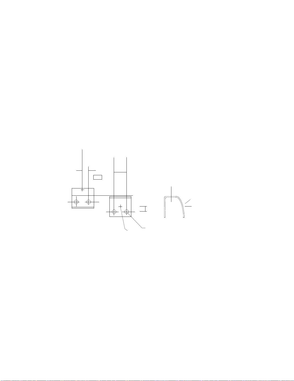
Figure 2. Clamp and Mirror Method
Figure 3. Mirror Mounting Template
2.2 Angle Bracket Method
The other mounting bracket supplied is a reflectorized 45°angle bracket. This bracket allows the
UVISENSOR to be mounted on the side or top of the lamp's reflector housing. Figure 4 shows two typical
installations.
The bracket is mounted by drilling four 0.096 diameter holes and securing it to the lamp housing with the #4
sheet metal screws supplied in the kit. The UVISENSOR is retained in the bracket by sliding it into the large
holes in the bracket and pressing one of the large internal-tooth fasteners supplied on each end of the
UVISENSOR. Figure 4 shows the angle bracket mounting details and also provides a drill template for this
bracket.
In Figure 5A, the angle bracket with the UVISENSOR is mounted on the side of the reflector housing. A
1/4" diameter hole has been drilled through the side of the housing and reflector. This bracket arrangement
allows the UVISENSOR to look directly across the assembly at the far side of the lamp reflector.
.219.438
.17
CENTERLINE OF SENSOR
.125 0 HOLE IN MIRROR
4 PLACES
CENTER OF MIRROR
OPPOSITE SIDE
LIGHT SOURCE
CENTERLINE
OF
SENSOR
MultiBriteOperator's Manual
7
Figure 5B shows a similar installation with the UVISENSOR looking down at the top of the lamp through a
1/4" diameter hole. In this configuration, the UVISENSOR must look at the lamp and not beside it. This is
to prevent the UVISENSOR from seeing reflections from the work surface below the lamp. Be certain to
remove the protective film from the mirrored surface inside the bracket.
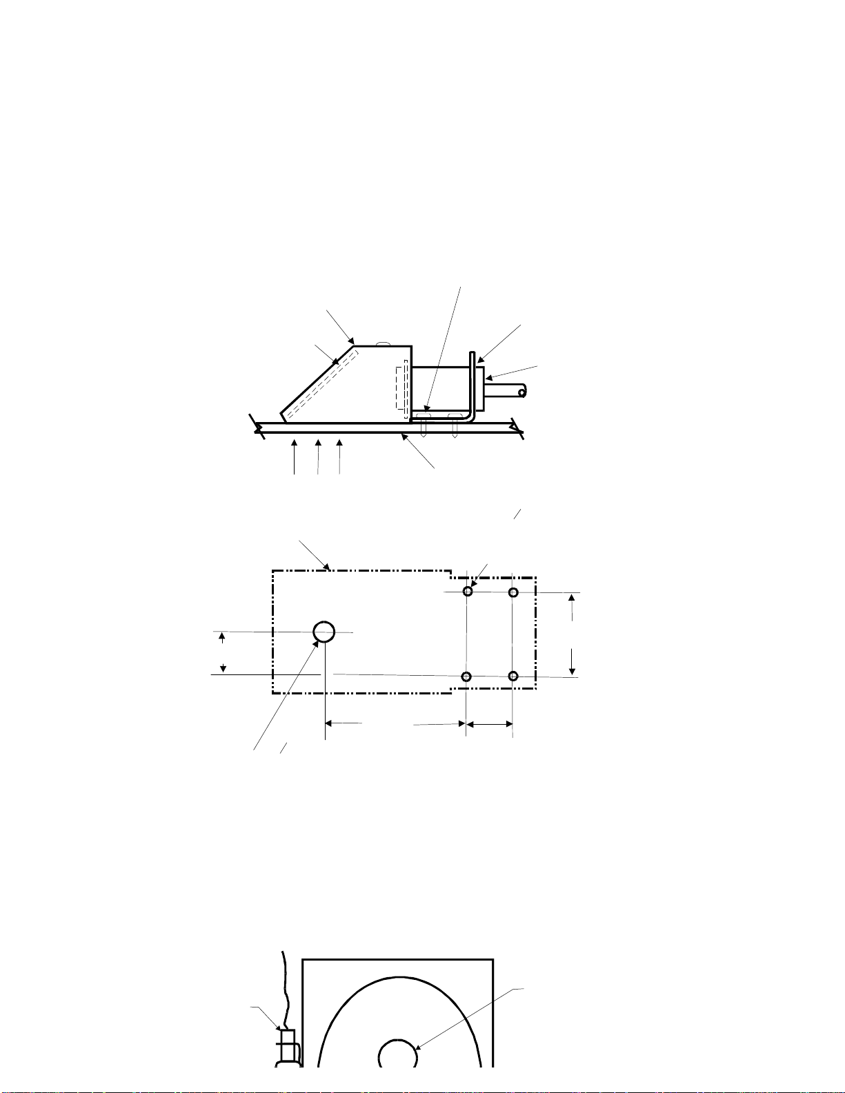
Figure 4. Bracket Mounting Drill Template.
1.75
.53 1.062
.25 O HOLE FOR LIGHT SOURCE
.562
BRACKET OUTLINE
.095 O (NO. 40 DRILL) HOLES
REQD IN MOUNTING SURFACE
IF USING SCREWS PROVIDED
IN MOUNTING KIT
4 PLACES
REMOVE PROTECTIVE
FILM FROM MIRROR
INSIDE OF BRACKET
BRACKET
MOUNTING HARDWARE
4 PLACES
FASTENER ON EACH
END OF SENSOR
SENSOR
MOUNTING SURFACE
LIGHT SOURCE
BRACKET MOUNTING DETAIL
UVISENSOR
LAMP

MultiBriteOperator's Manual
8
Figure 5. Typical 45º Bracket Installation
2.3 UVISENSOR Wiring
The cable from the UVISENSOR must be routed to the MultiBrite in such a way so as to avoid contact with
the moving equipment, workpieces, lamp bodies and lamp cabling. Use appropriate cable clamps or ties as
necessary to secure the cable.
CAUTION
Do not allow the UVISENSOR body or cabling to touch the lamp, lamp cabling, or end caps.
Allow at least one inch clearance between the sensor and these areas to prevent arcing or
insulation damage.
WARNING
The ends of the lamp and the cables feeding them may have several thousand
volts present. TURN OFF ALL POWER TO THE EQUIPMENT. UNDER NO
CIRCUMSTANCES SHOULD ANYONE ATTEMPT TO PERFORM
MAINTENANCE WHEN LAMP(S) OR EQUIPMENT ARE POWERED. The
lamps, their end caps, and cabling are very hot. Contact with these areas will
result in serious burns. ALLOW EQUIPMENT TO COOL BEFORE ATTEMPTING
TO CLEAN THE UVISENSOR.
MultiBriteOperator's Manual
9
2.4 Cleaning the UVISENSOR and Mirror
Whenever the UV lamp or its reflector are cleaned or replaced, the glass window of UVISENSOR should be
cleaned at the same time. Before proceeding, turn OFF all power to the UV equipment and allow it to cool.
Using a Q-tip dipped in denatured alcohol clean the glass window of the UVISENSOR and wipe it dry with
a lint-free cloth. Repeat this procedure on the mirror and/or reflectorized surface of the angle bracket, as
appropriate. The angle bracket will have to be removed from its mounting surface to gain access to its
reflector. Do not touch the mirror or reflector after cleaning.
Note that after relamping or cleaning reflectors, the MultiBrite should be recalibrated
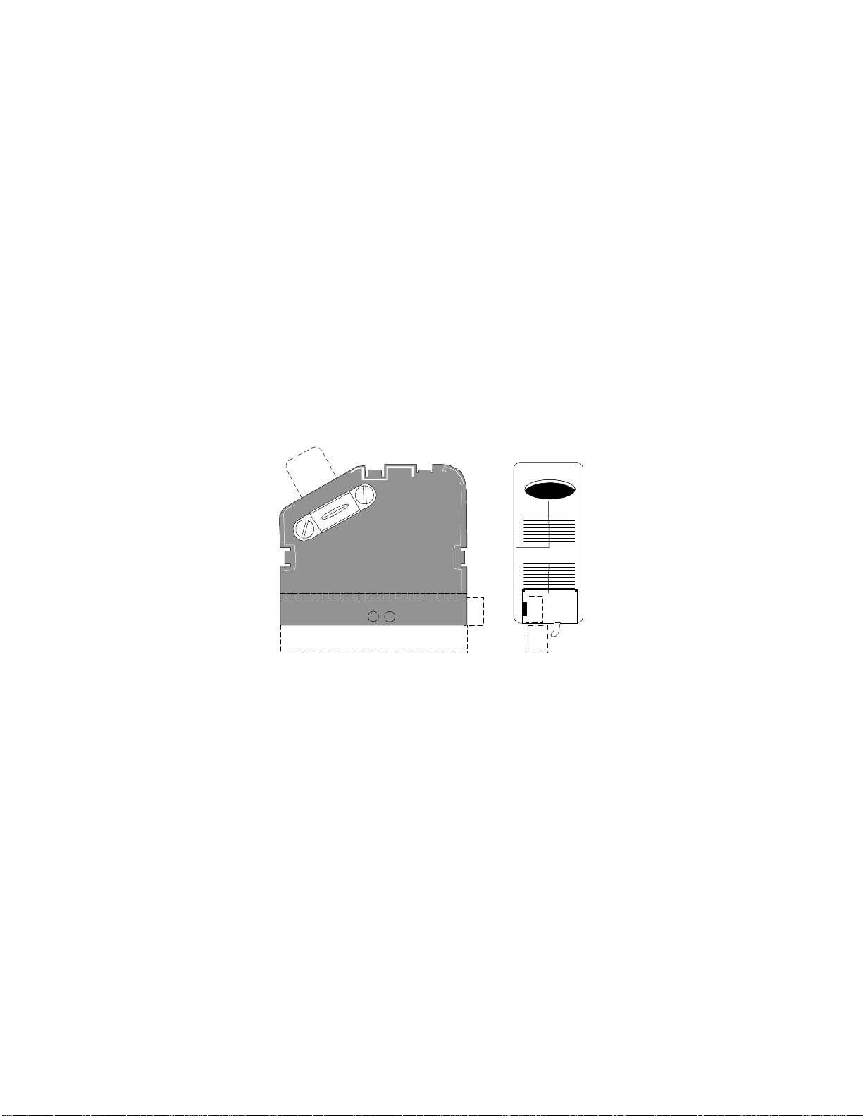
2.5 Terminal Blocks
The MultiBrite is provided with pluggable terminal blocks. This type of connector allows the MultiBrite
terminal blocks to be wired then plugged into the mating connector on the back of the MultiBrite. Strain
relief shells and marking strips are also provided to be installed by the user. The strain relief clamp attaches
to the shell with the provided screws. The shell clamps over the terminal block connector and snaps together.
The marker strip slides into the transparent corner piece. The corner piece then snaps into the shell assembly.
Figure 6 shows the strain relief shell assembled to the terminal block.
Figure 6. Terminal block with strain relief shell attached
2.6 Alarm Connections
Two alarm outputs are available from the MultiBrite system. The Low Intensity Alarm Relay output
available at terminals 15, 16, and 17 of the upper bottom back panel connector indicates the failure of any
one of the lamps being monitored by the MultiBrite system. This alarm output is available as a normally
open (NO) relay contact and a normally closed (NC) relay contact. When the alarm condition exists, the
normally open contact exists, the normally open contact will open and the normally closed contact will close.
While the intensity of the lamps being monitored are above the selected threshold level, the alarm relay will
be energized, closing the normally open contacts and opening the normally closed contacts. These contacts
may be used to control any external alarm device requiring a driving voltage less than 125 volts AC with a
resistive load current less than 0.5 Ampere or 110 volts DC with a resistive load current less than 0.3
ampere. Connections to the Low Intensity Alarm Relay are totally flexible for the users application. The
contact configuration is illustrated in Figure 7.

MultiBriteOperator's Manual
10
Figure 7. Low intensity alarm contact configuration
The second set of alarm contacts may be used to verify power has been applied to the MultiBrite System and
a control signal has been applied to the Lamp Power Detection Input. This alarm output is available as a
normally open (NO) relay contact and a normally closed (NC) relay contact. When power is applied to the
MultiBrite System and a control signal has been applied to the Lamp Power Detection Input, the normally
open contact will be energized closing the normally open contacts and opening the normally open contact
will close and the normally closed contact will open. The alarm relay will be energized closing the normally
open contacts and opening the normally closed contacts until power is lost in the MultiBrite System or the
Lamp Power Detection Input signal is removed. These contacts may be used to control any external alarm
device requiring a driving voltage less than 125 volts AC with a resistive load current less than 0.5 ampere
or 110 volts DC with a resistive load current less than 0.3 ampere. Connections to the Lamp Power Alarm
Relay are totally flexible for the users application. The contact configuration is illustrated in Figure 8.
Figure 8. Lamp power fail alarm contact configuration
The Lamp Power Alarm contacts may also be used to control the external alarming circuitry. For example, it
may be necessary to determine an alarm condition exists because of a power failure instead of a lamp failure.
The circuit illustrated in Figure 9 will disable the alarm whenever the Lamp Power Alarm Relay indicates a
loss of lamp power. An alarm condition will be indicated only if the output of one or more of the lamps is
below the selected intensity level and the lamp power alarm relay indicates lamp power is present.
Figure 9. Power Alarm Disable Example
2.7 Signal Output Connections
The MultiBrite Monitoring System is equipped with a 0 to 10 volt output section and a 4 to 20 mA current
transmitter section for each channel. These sections can be individually user adjusted for various outputs for
a given intensity range as shown in Table 1. These outputs allow a wide range of process control and
monitoring equipment to be interfaced with the MultiBrite.
Intensity
Range Voltage Output
Signal Range Current Output
Signal Range S1 thru S4
Position
0 to 100% 0 to 10 volts 4 to 20 mA 1
0 to 200% 0 to 10 volts 4 to 20 mA 2
0 to 100% 0 to 5 volts 4 to 20 mA 3
Alarm Common 16
15 Alarm NO
17 Alarm NC
Alarm Common 19
18 Alarm NO
20 Alarm NC
Lamp Power
Alarm Relay NO
Contact
Low Intensity
Alarm Relay NC
Contact External Alarm
Device
L1 L2
17161819

MultiBriteOperator's Manual
11
Table 1. Output Selection Table.
Caution must be exercised in connecting the signal loads to the system because the four connectors on the
back panel are identically the same. For convenience, the signal wiring may be attached to the connector
terminal strip before the connector is inserted into the mating back panel connector. Figure 10 illustrates the
connector layout.
CHANNEL 1
0-10 VOLT CHANNEL 2
0-10 VOLT CHANNEL 3
0-10 VOLT CHANNEL 4
0-10 VOLT
+-GRD +-+-GRD +-
31 32 33 34 35 36 37 38 39 40 Upper Top
Connector
21 22 23 24 25 26 27 28 29 30 Lower Top
Connector
+-+-+-+-
CHANNEL 1
4-20MA CHANNEL 2
4-20 MA CHANNEL 3
4-20MA CHANNEL 4
4-20MA
LOOP POWER
SUPPLY
POSITIVE
Figure 10. Back Panel Analog Connector Definitions.
2.7.1 0 to 10 Volt Output Connections
A continuous analog voltage output is available for each of the 4 lamp monitor channels in the
MultiBrite System. The 0 to 10 volt output signal is capable of driving a resistive load greater than 10K
Ohms. Connections to the output should be made using a twisted pair shielded cable with the shield
terminated at the MultiBrite output terminal block. The 0 to 10 volt output is a continuous voltage
analog representation of the relative intensity of the lamp being monitored. The voltage signal is directly
proportional to the percentage reading on the front panel display. Zero to 10 volts corresponds to zero to
100%.
Switches for each of the 4 channels inside the MultiBrite enclosure allow the user to select 3 different
continuous analog output options. The option described above, 0 to 10 volts out for 100%, is selected
inside the system before it is shipped from the factory. To change the option on the switches, the top
cover of the MultiBrite must be removed and the proper switch setting must be selected. The options
and their associated switch settings are summarized in Tables 2.4-1 and 2.4.1-1. To gain access to the
switches, remove the two screws on the top of the instrument near the front panel. Locate and remove
the 4 screws on the back panel of the instrument. With the 6 screws removed, the top cover-back cover
may be removed exposing the 4 switches. The desired option may be selected by using a screwdriver to
select the associated switch position.
MultiBriteOperator's Manual
12
CHANNEL 1
0 TO 10 VOLTCHANNEL 4
0 TO 10 VOLT
CHANNEL 3
0 TO 10 VOLT
CHANNEL 2
0 TO 10 VOLT
GUARDGUARD
Figure 11. 0 to 10 volt connections
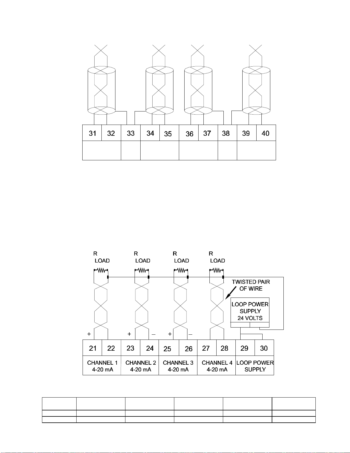
2.7.2 4 to 20 mA Output Connections
A continuous analog current loop output is available for each of the 4 lamp monitor channels in the
MultiBrite System. The 40 to 20 mA output signal is capable of driving a resistive load up to 250 ohms.
Connections to the output should be made using a twisted pair cable. The 4 to 20 mA output is a
continuous analog representation of the relative intensity of the lamp being monitored. The current loop
signal is directly proportional to the percentage reading on the front panel display. 4 to 20 mA
corresponds to 0 to 100% on the display.
_
_
+
_
+
Figure 12. 4 to 20 mA connections
Intensity
Range Channel 1
S 1 Channel 2
S 2 Channel 3
S 3 Channel 4
S 4 Output
Voltage
0 to 100% Switch Position 1 Switch Position 1 Switch Position 1 Switch Position 1 0 to 10 Volts
0 to 200% Switch Position 2 Switch Position 2 Switch Position 2 Switch Position 2 0 to 10 Volts

MultiBriteOperator's Manual
13
0 to 100% Switch Position 3 Switch Position 3 Switch Position 3 Switch Position 3 0 to 5 Volts
Table 2. Analog Voltage Output Selection Options.
Switches for each of the 4 channels inside the MultiBrite enclosure allow the user to select 3 different
continuous analog output options. The option described above, 4 to 20 mA out for 0 to 100%, is selected
inside the system before it is shipped from the factory. To change the option on the switches, the top cover of
the MultiBrite must be removed and the proper switch setting must be selected. The options and their
associated switch settings are summarized in Tables 1 and 2, and at the beginning of section 2.4. To gain
access to the switches, remove the two screws on the top of the instrument near the front panel. Locate and
remove the 5 screws on the back panel of the instrument. With the 7 screws removed, the top cover-back
cover may be removed, exposing the 4 switches. The option may be selected by using a screwdriver to select
the associated switch position.
Transmission of the 4 to 20 mA loop output to an external load should be through a twisted pair cable. There
are two terminals on the back panel connector to connect the + and - signal lines of each channel. The
positive side of the external 24-volt loop power supply connects to terminals 29 and 30. The negative side of
the supply connects to the - terminals (22, 24, 26, 28). Please refer to Figure 12 for an illustration of the
external power supply connections and the signal connection configuration for each channel. The 4 to 20 mA
signal for each channel is transmitted through terminals 21, 23, 25 and 27 as illustrated.
Intensity
Range Channel 1
S 1 Channel 2
S 2 Channel 3
S 3 Channel 4
S 4 Output
Current
0 to 100% Switch Position 1 Switch Position 1 Switch Position 1 Switch Position 1 4 to 20 mA
0 to 200% Switch Position 2 Switch Position 2 Switch Position 2 Switch Position 2 4 to 20 mA
0 to 100% Switch Position 3 Switch Position 3 Switch Position 3 Switch Position 3 4 to 20 mA
Table 3. Analog Output Current Loop Options
2.8 Power Connections
The MultiBrite Model #MB100AC1 is powered from a 90 to 132 volt AC power source. The MultiBrite
Model #MB240AC1 is powered from a 180 to 264 volt AC power source. Power is supplied to the system
through the upper bottom back panel connector. Caution must be exercised in connecting the power source to
the system because the four connectors on the back panel are identically the same. For convenience, the
power source wiring and the alarm wiring may be attached to the connector terminal strip before the
connector is inserted into the mating back panel connector. Figure 13 illustrates the connector layout.
For Model # MB100AC1 connect L1 of the 90 to 132 volt AC power source to terminal 11 of the upper
bottom back panel connector. For Model # MB240AC1 connect L1 of the 180 to 264 Volt AC power source
to terminal 11 of the upper bottom back panel connector.
For Model # MB100AC1 connect L2 of the 90 to 132 volt AC power source to terminal 12 of the upper
bottom back panel connector. For Model #MB240AC1 connect L2 of the 180 to 264 volt AC power source
to terminal 12 of the upper bottom back panel connector.
Connect the third wire ground of the incoming power source to terminal 13 of the upper bottom back panel
connector.
AC POWER ALARM LAMP POWER Upper Bottom
Connector
L1 L2 GND NO C NC NO C NC
11 12 13 14 15 16 17 18 19 20
12345678910

MultiBriteOperator's Manual
14
24V LAMP
POWER
DETECTION
(TIMER
INITIATION)
24V
CHANNEL
1
24V
CHANNEL
2
24V
CHANNEL
3
24V
CHANNEL
4
Lower Bottom
Connector
REMOTE CHANNEL DISABLE INPUTS
ALL REQUIRE 24 VOLTS AC OR DC
Figure 13. Back Panel Power Connector Definitions
2.9 Control Connections
2.9.1 Lamp Power Detection Input
In addition to the AC power source required to power the MultiBrite System, a Lamp Power Detection
Input is required to make the system operational. This input is used to determine when power has been
applied to the lamps in the curing system. Detection of power applied to this control input initiates a
time delay to the alarm circuit to prevent premature alarms prior to the lamps striking. A 24 volt AC or
DC input is required across terminals 1 and 2 on the lower bottom back panel connector, to enable the
alarm monitoring circuitry. The time delay prior to alarm monitoring is user programmable through the
switches on the back panel connector, to enable the alarm monitoring circuitry. The time delay prior to
alarm monitoring is user programmable through the switches on the back panel of the system. Time
delays from 5 seconds to 1275 seconds (21.25 minutes) may be programmed through the switches on
the back panel. The layout of the switches on the back panel is illustrated in Figure 14. The amount of
time delay is determined by adding the number of seconds associated with each switch in the ON (up)
position. For example, if switches 1, 4, 6, and 8 are in the ON (up) position, the alarm will be enabled 5
+ 40 + 160 + 640 = 845 seconds or about 14 minutes after the Lamp Power Detection input detects
power has been applied to the curing system lamps.
1 2 3 4 5 6 7 8
5
Secs. 10
Secs. 20
Secs. 40
Secs. 80
Secs. 160
Secs. 320
Secs. 640
Secs.
Figure 14. Time Delay Switch Configuration.
The Lamp Power Detection input requires a nominal input signal of 24 volts AC or 24 volts DC to
enable the alarm detection circuitry of the MultiBrite System. This input must be provided even if a zero
time delay is selected with all switches in the OFF (down) position. Either or both input terminals should
be connected or disconnected from the 24 volt (AC or DC) input by controls applying power to the
lamps of the curing system.
2.9.2 Remote Channel Disable Inputs
A remote Channel Disable input is available for each of the four monitor channels. Control inputs for the
respective channels are located on the lower bottom back panel connector as illustrated in Figure 13. The
disable inputs have identical functionality causing a channel alarm to be suppressed when 24 volts AC
or DC is applied to the appropriate terminals. External control circuitry used to place a specific lamp in
"Low Power", standby, or disconnect mode may be used to provide the 24 volt AC or DC input to

MultiBriteOperator's Manual
15
suppress the alarm condition for the specified channel. Application of the control voltage to the
appropriate terminal block connections will inhibit the alarming of the associated channel locally as well
as remotely. Disabling a channel does not prevent the monitoring of the intensity level for that channel
on the 2 digit panel display. The 0 to 10 volt or the 4 to 20 milliamp outputs are not affected by the
remote channel disable inputs.
A channel may be permanently disabled by hard wiring that channel's disable input to 24 volts (AC or
DC). This is useful in OEM applications when less than four lamps are to be monitored. The Remote
Disable input overrides the front panel switch for that given channel. If a channel is disabled from the
Remote Channel Disable input, it cannot be enabled from the front panel. Table 4 defines the terminals
to which 24 volts must be applied to disable the designated associated channel.
TO DISABLE
CHANNEL CONNECT 24 VOLTS
ACROSS TERMINALS
13 and 4
25 and 6
37 and 8
49 and 10
Table 4. Channel Disable Inputs.
3. SPECIFICATIONS
3.1 Display
Three digit liquid crystal display (LCD), 0.5" high digits.
Display channel selection by turning a rotary switch to the desired channel. Display range of 0 to 199% can
be displayed.
3.2 Operating Temperature
Operating temperature is 0 to 50 degrees Celsius.
3.3 Sensor Input Current Range
MultiBrite was designed for use with EIT UVISENSORS.
Current range through the sensor input terminals is 0.2 to 2.0 microamperes for a "100%"full scale reading.
Display reading is adjustable by turning a respective channel's screw slotted "CALIBRATE"control located
on the front panel.
3.4 Signal Output Specifications
Three different signal output configurations for each channel.
Position 1:0 to 100% output represented by 0 to 10 volts DC and 4 to 20 mA DC.

MultiBriteOperator's Manual
16
Position 2:0 to 200% output represented by 0 to 10 volts DC and 4 to 20 mA DC.
Position 3:0 to 100% output represented by 0 to 5 volts DC and 4 to 20 mA DC
Refer to section 2.4 for a description of these configurations.
3.4.1 Current Loop Output
Current loop outputs for the individual channels are available on terminals 21 through 30 located on the
rear panel. See Figure 12 for connection information.
Current output: 4 to 20 mA output current range will drive loads less than 250 ohms.
24 volt external power source requirements: 18-28 volts, 250 mA minimum current capacity.
3.4.2 Voltage Output
Voltage outputs for the individual channels are available on terminals 31 through 40 located on the rear
panel. The output voltage range is switch selectable for 0 to 10 volts or 0 to 5 volts. Refer to Table 1 for
switch selection information. See Figure 11 for connection information.
Voltage output:0 to 10 volts will drive loads greater than 10K ohms.
0 to 5 volts will drive loads greater than 5K ohms.
3.5 Alarm Outputs
3.5.1 Contact Ratings
Alarm outputs are available on terminals 15 through 20. Refer to section 2.3 for a description of the
alarm outputs of the MultiBrite. See Figures 7 and 8 for connection information.
0.5A at 125VAC
Resistive load
3.5.2 Alarm Trip Point Accuracy
The trip point accuracy for the alarm is +/- two display counts.
The alarm will reset at a measurement level 2 to 4 counts above the set alarm trip point.
3.6 Input Power Requirements
Input power to MODEL # MB100ACI MultiBriteTM is 90 to 132 VAC, 47 to 440 Hz, 0.20 amperes.
Input power to MODEL # MB240AC1 MultiBriteTM is 180 to 264 VAC, 47 to 440Hz, 0.20 amperes.
3.7 Weight
MultiBriteOperator's Manual
17
Weight approximately forty-eight ounces.
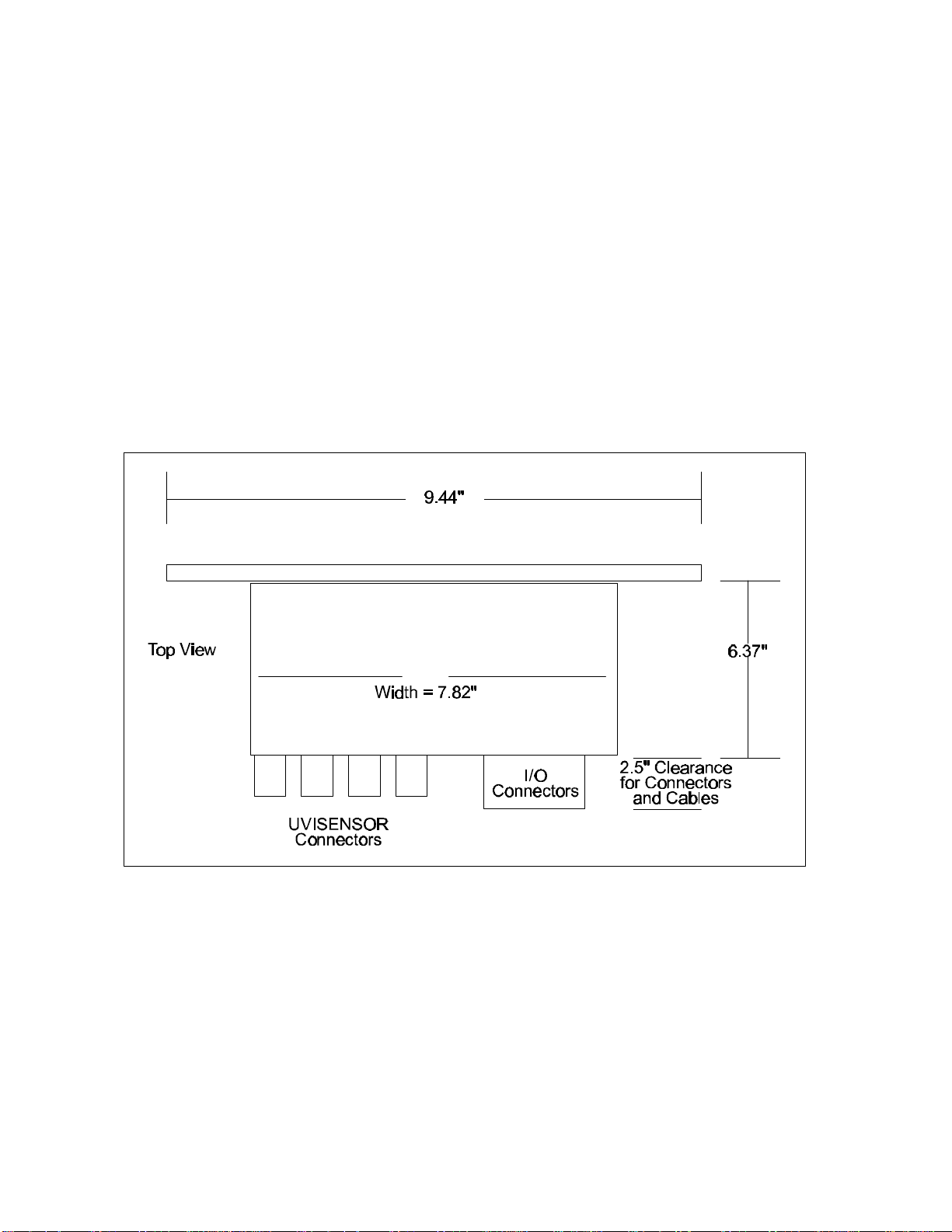
3.8 Dimensions
The enclosure portion is 7.82 inches wide by 3.5 inches high by 6.37 inches deep (7.82”W x 3.5”H x 6.37”
D).
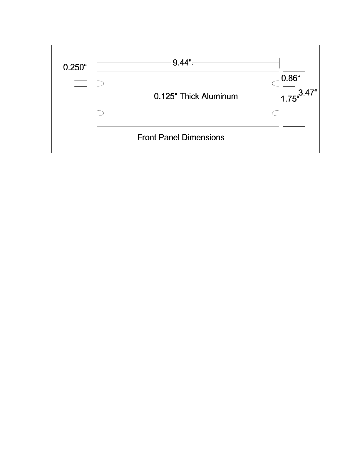
The front panel is 9.44 inches wide by 3.5 inches high by 0.125 inches thick (9.44”W x 3.5”H x 0.125”T).
3.9 Construction
Painted aluminum with integral mounting flanges on the front panel.
Mounting: Designed for panel mounting (1/2 rack dimensions).
Figure 15. MultiBrite top view, dimensional diagram
The strain relief shell, described in section 2.2, can be removed from the I/O connectors to reduce the
connector/cable clearance from 2.5” to 1.5”.
MultiBriteOperator's Manual
18
9.44"
Figure 16. MultiBrite front view dimensional diagram
4. CALIBRATION AND OPERATION
4.1 Calibration
To calibrate the MultiBrite system, perform the following steps:
1. Make sure that the UVISENSOR(s) and the MultiBrite components have been properly installed (see
section 2.1).
2. Ensure that the UV lamp(s) to be monitored are new or are considered to be at 100% output.
3. Power the lamps and allow sufficient time to achieve full UV intensity.
4. Set the front panel rotary switch to the desired channel. Using a small screwdriver turn the CAL
adjustment of the selected channel to obtain a reading of 100 on the display. Rotate the CAL adjustment
screw clockwise to increase the displayed reading and counter-clockwise to decrease the reading.
5. Repeat step 4 for the remaining channels.
6. Select the LOWER LIMIT position on the front panel rotary switch. Using a small screwdriver turn the
LL adjustment to obtain the desired trip point for the alarm. The alarm will trip at this point ± two
display counts. The alarm will reset if the measurement signal rises to within two to four display counts
above the set threshold.
7. Refer to section 5, "Applications", for additional information regarding the use of MultiBrite.
This manual suits for next models
1
Table of contents
Other EIT Measuring Instrument manuals


Popular Measuring Instrument manuals by other brands


Vanguard Instruments
Vanguard Instruments Auto-Ohm 200 S3 user manual

CIMCO
CIMCO 11 1410 operating instructions

Akron
Akron Style operating instructions

Agilent Technologies
Agilent Technologies 1680 series Service guide

Endress+Hauser
Endress+Hauser eco-graph operating instructions

Konig Security
Konig Security SEC-DVR200 manual


