EIT UV Power Puck II User manual

EIT Part Number P/N IM-0111 Rev A Issued April 2019
EIT
®
UV Power Puck
®
II & UviCure
®
Plus II
User’s Guide
Electronic Instrumentation and Technology (EIT) LLC
309 Kelly’s Ford Plaza SE
Leesburg VA 20175 USA
Phone: 703-478-0700
Email: [email protected]m
Web: www.eit.com

EIT Part Number P/N IM-0111 Rev A Issued April 2019
Table of Contents
Introduction............................................................................................................................................................................. 1
The Process Values................................................................................................................................................................. 1
Operation and Features ........................................................................................................................................................... 2
Operating the Radiometer ....................................................................................................................................................... 4
Data Collection Techniques.................................................................................................................................................... 7
Diagnostics & Error Messages ............................................................................................................................................. 13
Low Battery Indicator ....................................................................................................................................................... 13
Over-Temperature State .................................................................................................................................................... 13
Over Range State............................................................................................................................................................... 13
Other Error Codes ............................................................................................................................................................. 13
Maintenance – Cleaning and Calibration ............................................................................................................................. 14
Cleaning-Display............................................................................................................................................................... 14
Calibration......................................................................................................................................................................... 14
EIT UV Instrument New Product and Calibration/Repair Warranty ................................................................................... 16
Appendix A: Optics Cleaning............................................................................................................................................... 17
Appendix B: Specifications .................................................................................................................................................. 19
Appendix C: Instrument Types and Software....................................................................................................................... 20
Appendix D: Regulatory Statements .................................................................................................................................... 22
EIT Part Number P/N IM-0111 Rev A Issued April 2019
Page 1
Introduction
The EIT UV Power Puck® II and UviCure® Plus II are used globally for industrial UV measurement and process
control. With user selectable sample rates, reference modes, UV irradiance profile graphs and other features, these
instruments can be used for fast or slow conveyor lines and the measurements are compatible with other EIT products.
The instruments are simple to use with one-button operation.
The UV Power Puck II and UviCure Plus II are self-contained, electro-optic radiometers that measure and display total
UV energy and UV irradiance in a UV curing system. The UV Power Puck II and UviCure Plus II combine compact size
and robust design to withstand the extremes of UV curing environments while providing accurate measurement.
The carefully designed optical sensing systems only measure wavelengths that are relevant to the UV process. The
output of the sensing system is converted to digital form and displayed on an easy-to-read OLED display.
The UV Power Puck II simultaneously measures four different ranges of ultraviolet wavelengths with one pass through
the UV process. The UV Power Puck II default wavelengths are UVA (320-390nm), UVB (280-320nm), UVC (250-
260nm) and UVV (395-445nm). The UviCure Plus II includes a choice of one of the EIT wavelength bands.
The instrument reading includes total energy and peak irradiance of all four transmission bands for the UV Power Puck
II and one band for the UviCure Plus II.
The EIT UV Power Puck II and UviCure Plus II are designed and manufactured in the USA.
The Process Values
Reaching the energy density and irradiance values specified by your process along with the proper bulb type is
necessary for achieving consistent acceptable UV cure.
The two process values read by the UV Power Puck II and UviCure Plus II are peak irradiance and total energy
density.
The irradiance reading is the peak intensity measured during the exposure run. The radiometers measure and display
irradiance in Watts, milliWatts or microWatts per square centimeter (W/cm
2
, mW/cm
2
, µW/cm
2
). If the unit is used to
measure multiple lamps, the peak irradiance value will correspond to the most intense lamp.
Total energy density (sometimes called dose) is a factor of the irradiance over time. The instruments derive this value
from the irradiance values during the exposure run and the length of time of the run. Total energy is measured in
Joules, milliJoules or microJoules per square centimeter (J/cm
2
, mJ/cm
2
, µW/cm
2
). If the unit is used to measure
multiple lamps, the total energy density value will be the sum of all lamps.
Ultraviolet Radiation
This product is not a source of UV radiation (energy/light).
It is used in an environment where UV is present and protective
measures (eye/skin) against UV radiation should be followed.
Refer to the UV source's documentation for information.
EIT Part Number P/N IM-0111 Rev A Issued April 2019
Page 2
Operation and Features
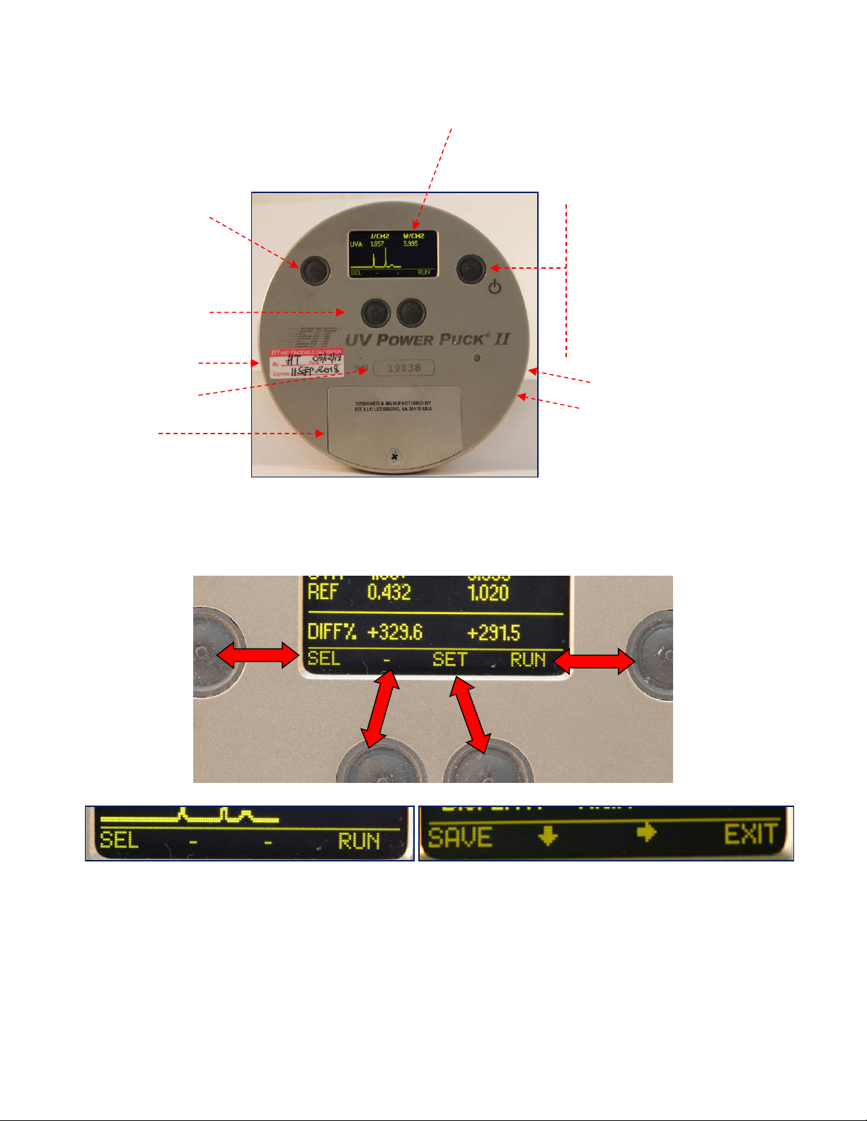
Button Operation
The four buttons on the face of the instrument correspond to the adjacent function shown on the display. The functions will
change automatically based on the instrument mode. Examples of different functions are shown below.
Setup Mode Button On / Off Button
Depress and Hold until
screen is illuminated.
Run / Exit Run Button
Press to enter Run
Mode.
Press to Exit Run Mode.
Display
Battery Door
Unit Serial Number
Soft Button Operation
Buttons perform the
function indicated on the
display bottom line.
See below
USB Port
Used for calibration and
data communication in
Profiler enabled
instruments
Alarm
Examples of some of the different functions that will be shown under the instrument display
Calibration Label
EIT Part Number P/N IM-0111 Rev A Issued April 2019
Page 3
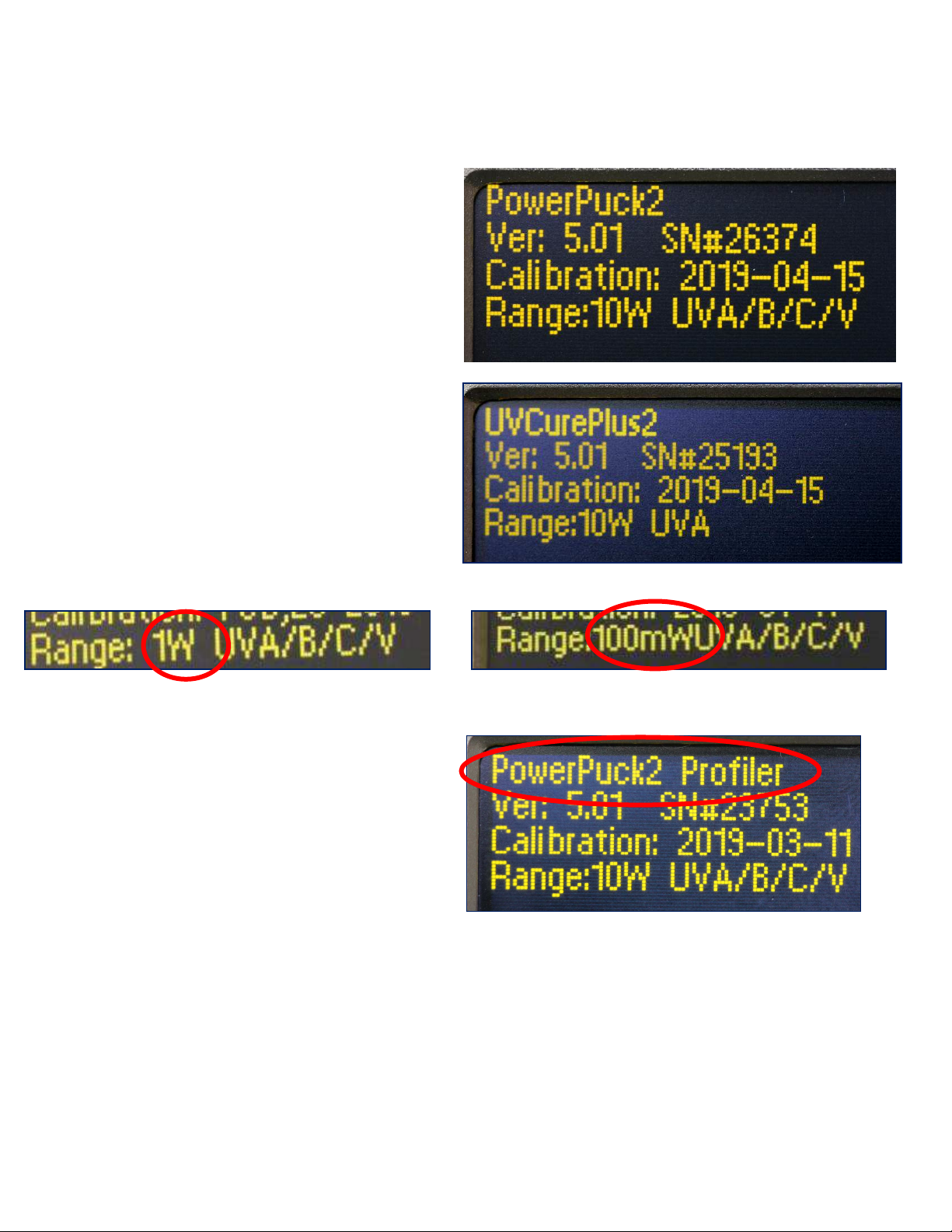
Unit Type
The first screen displayed momentarily when the unit is turned on will indicate the unit type and dynamic range. Pushing
and holding the On/Off Button will keep the display on this screen.
Unit Type (Standard Power Puck II)
Internal Firmware Version & Serial Number
Last Calibration Date
Dynamic Range (10 Watts) and UV bands
(UVA, UVB, UVC & UVV)
Unit Type (UviCure Plus II)
Internal Firmware Version & Serial Number
Last Calibration Date
Dynamic Range (10 Watts) and UV band (UVA)
Above Left: Unit with Dynamic Range of 1 Watt
Above Right: Unit with Dynamic Range of 100
milliWatts
Right: Power Puck II Profiler on Startup screen.
See Appendix C for more information on the
Profiler Versions of our instruments

EIT Part Number P/N IM-0111 Rev A Issued April 2019
Page 4
Operating the Radiometer
Turning “ON” the Radiometer: Press and Hold the ON / OFF button until the display illuminates. The display will
briefly display the Radiometer Model Name, Serial Number, Software Version, Calibration Date, Range, and
Wavelength Bands installed. (See previous page) The display will then enter the default mode and display the data
from the last run before the unit was turned off.
Turning “OFF” the Radiometer: Press and Hold the ON / OFF button. A tone will sound. When tone stops, release
the button. The unit turns off.
Entering the “RUN” MODE: A short press of the “RUN” button clears the memory and puts the unit in the “RUN”
mode. The display shows “RUNNING” after shortly displaying the internal temperature of the unit. Confirm that the
unit displays “RUNNING” before initiating a reading.
Place the radiometer on the belt or object with the optic window looking toward the UV source. The display and buttons
will be facing away from the UV source. When the radiometer exits the curing chamber, the display will still be flashing
“RUNNING”.
CAUTION: Exposing the display to high UV radiation will damage the display.
Exiting the “RUN” MODE: A short press of the “STOP” button (Soft button display bar indicates “STOP” next to the
“ON / OFF” button) will exit the “RUN” mode and will return to the same default mode prior to making the exposure
run, but will display the new value.

EIT Part Number P/N IM-0111 Rev A Issued April 2019
Page 5
Setup & Default Modes
To enter the Setup Mode, use the soft button to the left of the display, Press and hold for 0.5 second, then release.
The Setup screen will display the current settings. Default modes are designated using an *asterisk.
The setup screen below shows all possible choices for each mode.
To change selections, use the down and right arrow buttons located under the arrows to scroll in the
indicated direction. To change the default selection, first select the line, then the setting on each line. Press the
SAVE button to save the setting as the new default. An *asterisk will appear next to the setting.
When changes are completed, press the EXIT button to return to the default mode.
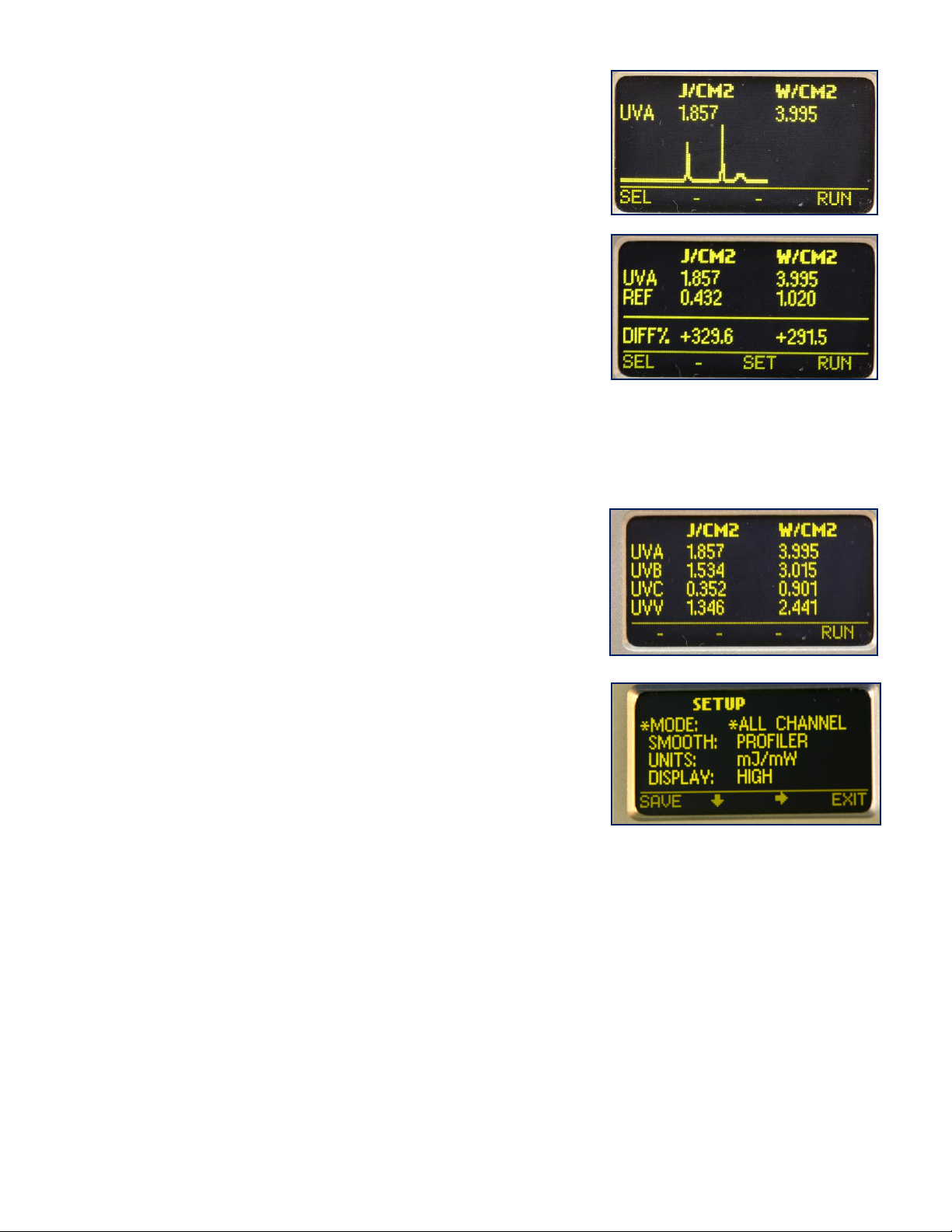
SETUP
*MODE: *ALL CHANNEL REFERENCE GRAPH
SMOOTH:*OFF ON
UNITS: *J/W mJ/mW uJ/ uW
DISPLAYS: LOW *MEDIUM HIGH
SAVE EXIT
SETUP
*MODE: *GRAPH REFERENCE TOGGLE
SMOOTH: *OFF ON
UNITS: *J/W mJ/mW uJ/ uW
DISPLAYS: LOW *MEDIUM HIGH
SAVE EXIT
UviCure Plus II Setup Screen
UV Power Puck II Setup Screen
EIT Part Number P/N IM-0111 Rev A Issued April 2019
Page 6
Explanation of Settings:
MODE:
GRAPH – Illustrates the irradiance profile for the UV source(s). UV
Data is stored and displayed as a graph of time (X axis) vs.
intensity (Y axis) for each UV lamp source.
REFERENCE – Make a run, data will appear next to the UV band.
CAUTION: Be sure you want to overwrite the current data on
the REF line before pressing SAVE. Press SAVE, data is
transferred to the REF line. The data will remain until it is
overwritten. The difference or change between the current run
data and the reference data is displayed as a percentage change
on the DIFF% line.
TOGGLE (UviCure Plus II Only) – Pressing the SEL button, the user can “toggle” between the GRAPH and
REFERENCE modes shown above.
ALL CHANNEL (UV Power Puck II Only) – displays Joules and
Watts for each of the four (4) UV bands (UVA, UVB, UVC, UVV)
SMOOTH: There is a detailed discussion of SMOOTH in the
Instrument Sample Rate section of the User’s Guide
UNITS: J/W, mJ/mW, µJ/ µW – Select the unit values
DISPLAYS: LOW, MEDIUM, HIGH – Select the display intensity
SAVE EXIT – Soft Button Indicators

EIT Part Number P/N IM-0111 Rev A Issued April 2019
Page 7
Data Collection Techniques
Collect the data in a consistent manner for consistent results. The following techniques will help you to get better
data with the Power Puck II or UviCure Plus II.
1. Match the Instrument Response to the source
•The Power Puck II and UviCure Plus II bands (UVA, UVB, UVC and UVV) were designed and
optimized for mercury based sources
•Your will get numbers on the instruments when they are used on a LED but chances are the numbers
will be under or over reported and vary source-to-source and instrument-to-instrument
2. Match the Dynamic Range of the instrument to the source
•The Power Puck II and UviCure Plus II are available in three dynamic ranges
•The ranges below are based on the irradiance (intensity) of the source, not the number of Joules that
will be collected
•Suggested Operating Ranges for Power Puck II and UviCure Plus II instruments
o10 Watt Standard (High- H) Range:
UVA, UVB, UVV - 100mW/cm² to 10W/cm²
UVC - 10mW/cm² to 1W/cm²
o1 Watt Mid (M) Range:
UVA, UVB, UVV -10mW/cm
2
to 1W/cm
2
UVC: 1mW/cm
2
to100mW /cm
2
o100 milliWatt Low (L) Range:
UVA, UVB, UVV - 1mW/cm² to 100mW/cm²
UVC - 1mw/cm
2
to 100mW/cm
2
•Units will “turn on” (Start Threshold) at a much lower value than the Suggested Operating Range
values
•Using an instrument outside of the Suggested Operating Ranges can lead to variations in the readings
oIf the unit is used well below the Suggested Operating Range, there can be variations in the
Joules, especially on long runs
oIf you try to use an instrument on a source well above the Suggested Operating Range, you
may wind up ‘maxing’ out the unit on each run
3. Follow EIT Optics Cleaning Guidelines
•Your Power Puck II or UviCure Plus II is an electro-optical instrument designed to measure UV in an
harsh environment
•Follow the Guidelines in Appendix A of this User’s Guide for proper cleaning techniques
•The Guidelines as well as an instructional video on proper cleaning techniques are posted on our
website at: https://www.eit.com/products/care-and-cleaning
4. Use Consistent Data Collection Techniques
•For best results, place the instrument in the same location with
the optics in the same orientation
•A small index mark on UV System allows the user to align the
optics in the same location and orientation each time on the
conveyor
•On wide arc based systems, consider taking multiple readings
(left-middle-right) across the width of the conveyor
5. Evaluate your UV System Stability
•Allow your system to warm up and stabilize per the
recommendations of the manufacturer.
•Avoid Human Error
oDouble check and confirm the applied power and
speed controller settings before taking a reading
oApplied power and speed controller settings are not always linear and can vary widely
EIT Part Number P/N IM-0111 Rev A Issued April 2019
Page 8
•With appropriate UV eye protection, check to make sure the instrument optics are maintained at a
consistent height throughout the path of travel in the UV system
oConsider the use of a fixture to stabilize the instrument height and to prevent ‘up and down
surfing’ motion between the rollers. This can lead to inconsistent Watt values.
6. Perform UV System Maintenance
•Keep reflectors clean and replace as needed
o60-80% of the UV energy arriving at the substrate comes off the reflector(s)
oReflectors with even a little contamination transmit less energy, especially in the shortwave (UVC)
region than clean reflectors
•Maintain the belt/conveyor tension to prevent slippage
oInconsistent speeds can lead to variations, especially in the Joule readings
•Verify the correct bulb type has been installed and that it is situated in the reflector as expected
•Purchase UV bulbs based on performance (output, life, spectral content) and not cost
oCarefully evaluate bulbs from new suppliers before switching
•Follow the maintenance recommendations for these parts of your UV system if present:
oCooling supply-air and or water
oPower Supply
oShutters
oQuartz Plates
oSpecialty (dichroic) Reflectors
oRF related items: Screens, gaskets and magnetrons
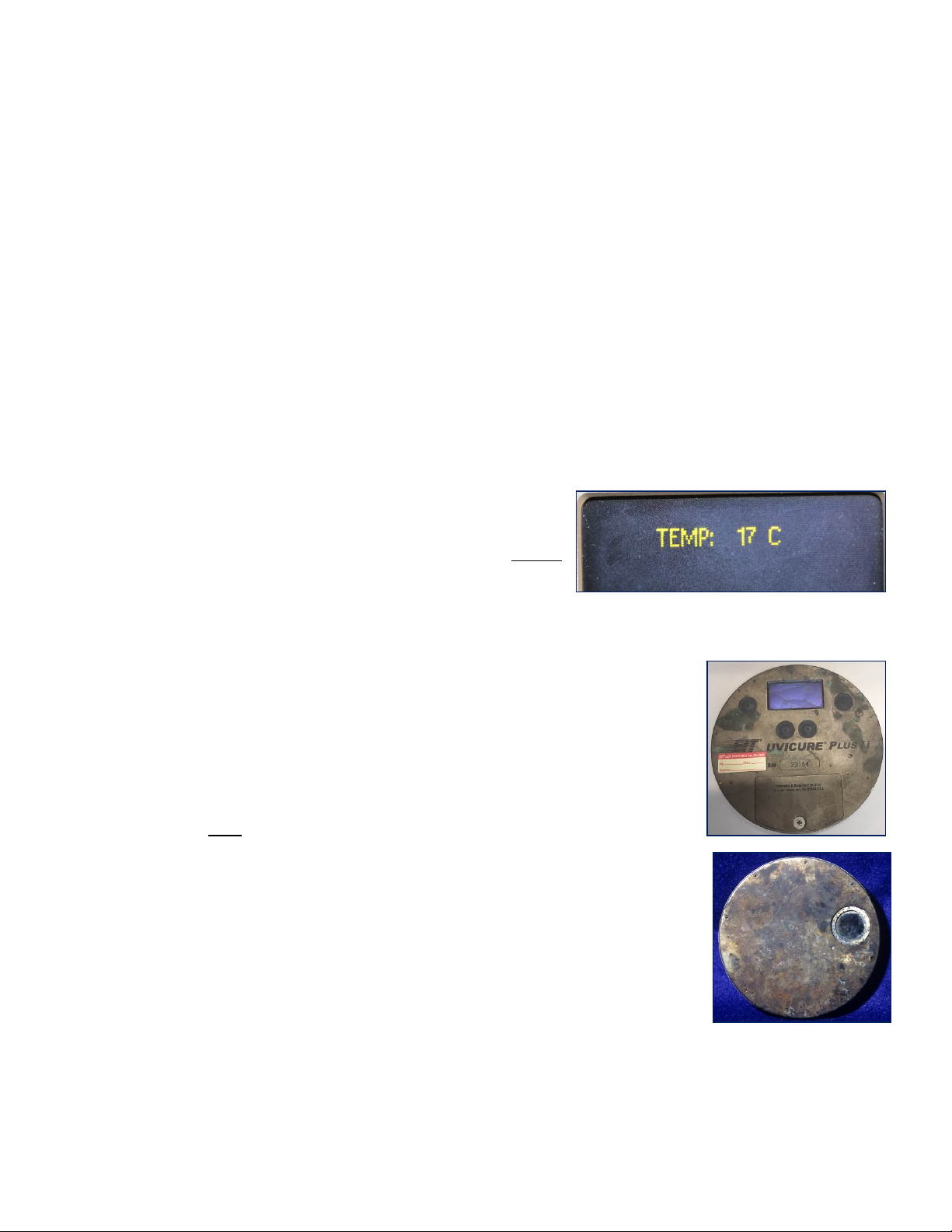
7. Watch the Instrument Temperature
•The internal temperature of instrument is shown on the
display each time “RUN” mode is activated
•An alarm will sound when the unit reaches an internal
temperature of 65°C or greater
•Avoid pre-heat, “flash-off” and/or IR sections of your line
•Repeated, slow long runs on high power UV systems without letting the instrument cool between runs can
damage the radiometer and/ or give inconsistent results
•Let the Power Puck II or UviCure Plus II cool between readings
•Rule of Thumb: If the instrument is too hot to touch, it is too hot to measure
8. Establish a process to Collect, Record & Maintain Instrument Values
•Based on your process, decide how and who will collect data. This includes:
oLine conditions
oSpeed and power levels
oFrequency of measurement
oInstrument settings (see section on Instrument Sampling below)
•Decide how to record/store
•Keep both the Joule and Watt values
9. Maintain Your Instrument
•EIT instruments are calibrated on a six month cycle. The Power Puck II and
UviCure Plus II can be used in harsh conditions including intense energy (UV,
visible, infrared), temperature and coatings
•Instruments can become coated, dropped or stuck in a system
•When your instrument needs service, use EIT or an EIT Authorized Service
Center
oEIT and our Authorized Service Centers have the training,
procedures and software to properly service your instrument
oIf repairs or replacement optics are needed, EIT and our Authorized
Service Centers have genuine replacement components
•EIT and our Authorized Service Centers can work with you to determine the
best bulb type to use when calibrating your instrument
Customer damaged
instruments
EIT Part Number P/N IM-0111 Rev A Issued April 2019
Page 9
10. Decide on the best Instrument Sample Rate for your application
•When comparing values within your supply chain, clarify what sample rate was used
•This is discussed in detail in the next section: Instrument Sample Rate
Instrument Sample Rate
Instrument Sample Rates
Collecting accurate, repeatable source values depends on getting an adequate number of
samples while the instrument is under the UV source. The area of peak irradiance normally
corresponds to the bulb diameter; typically 0.35-0.75” (9-19 mm).
EIT instruments designed in the early 1990’s were state-of-the-art for the time and featured
a ‘blazing’ sample rate of 25 Hz (samples per second). The two-button Power
Puck/UviCure Plus units had a maximum suggested ‘speed limit’ of 40 feet (12 meters) per
minute to allow the units to collect an adequate number of samples to measure the peak
irradiance and energy density values. Exceeding the suggested ‘speed limit’ when collecting
data would lead to variations, especially in the irradiance values.
As technology improved, the sample rates in our instruments have also dramatically increased. The PowerMAP
when released had a user adjustable sample rate of 128-2048 Hz (samples per second) and the MicroCure a
sample rate of 2048 Hz.
The data (especially the irradiance value) collected and displayed EIT instruments can vary based on the:
•Speed at which the data was collected
•The effective instrument sample rate which impacts how the irradiance values are reported
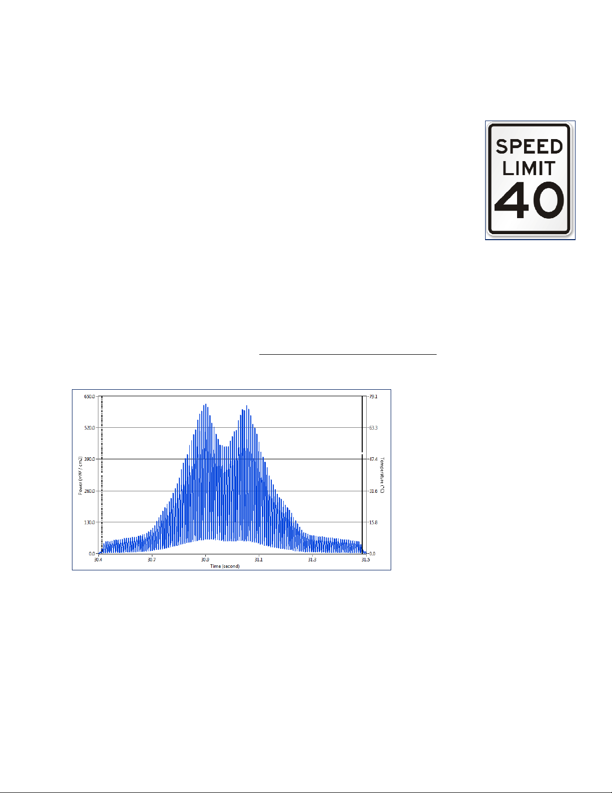
The two examples below show UVA data for the same exact lamp and conditions in two different ways. Both are
technically correct based on how you elect to measure the irradiance. Note: The X-Axis is time and the Y-Axis UV
irradiance
The data in this example was
collected at an effective sample rate
of 2048 Hz.
The peak UVA irradiance in this
example is 618.0 mW/cm
2
, the total
UVA energy density is 139.9 mJ/cm
2
If you zoom in (see next page), you
can see the lamp irradiance cycling
at the same frequency (usually 50 or
60 Hz) as the alternating current
(AC) from the power company.
The irradiance values and profile
shown are referred to as the instant
peak or “Smooth Off” intensity.

EIT Part Number P/N IM-0111 Rev A Issued April 2019
Page 10
The data in this example was
collected at an effective sample rate
of 128 Hz.
The peak UVA irradiance in this
example is 318.3 mW/cm
2
and the
UVA energy density is 139.9 mJ/cm
2
The irradiance profiles shows the
average RMS lamp power.
The irradiance values and profile
shown are normally referred to as
the Average Peak Intensity or
“Smooth Profiler” intensity.
This example shows a 0.30 second
section of the file collected at 2048
Hz.
It is clear from this example that the
power supply is cycling.
The irradiance values shown are
“Smooth Off” values at an effective
sample rate of 2048 Hz.
This example further zooms in on the
example collected at 2048 Hz and
shows a 0.03 second section.
It is clear that the power supply is
cycling.
The irradiance values shown are
“Smooth Off” values at an effective
sample rate of 2048 Hz.
EIT Part Number P/N IM-0111 Rev A Issued April 2019
Page 11
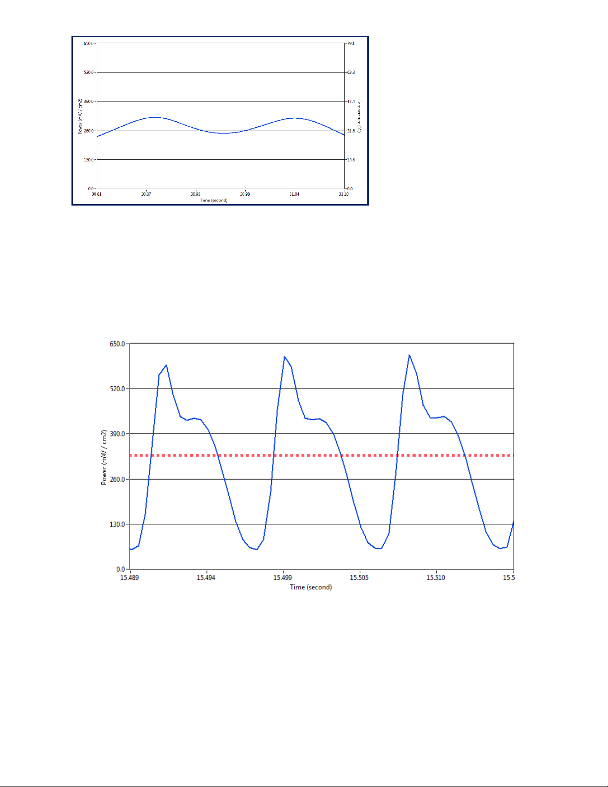
The irradiance profile below shows two other files.
•The time on the X-Axis is approximately 0.026 seconds
•The blue irradiance profile below shows data collected at 2048 Hz (SMOOTH OFF)
•The peak irradaince value for this blue file is 618 mW/cm
2
, EIT UVA
•The red irradiance profile below shows data collected at 128 Hz (SMOOTH PROFILER)
•The peak irradiance for this red file was 329 mW/cm
2
, EIT UVA.
•Both values are technically correct and are based on the how the UV was sampled and is reported.
Smooth/Smoothing
The UviCure Plus II and Power Puck II ‘oversample’ at a very high sample rate. The user is able to adjust the
effective sample rate to one of three settings in the set-up menu of the instrument.
The effective sample rate is based on the Data (not Optical) Filter Bandwidth. EIT instruments use different
bandwidths for the data filters.
From a technical standpoint we use 7, 35 and 700 Hz data filters in the UviCure Plus II and Power Puck II
instruments.
This example shows the same 0.30
second section of the UV lamp in the
top example on this page, with an
effective sample rate of 128 Hz.
The irradiance value is the RMS or
“Smooth Profiler” irradiance at an
effective sample rate of 128 Hz.
EIT Part Number P/N IM-0111 Rev A Issued April 2019
Page 12
The three data filters in the Power Puck II/UviCure Plus II units equate to the following sample rates:
•7 Hz : Effective sample rate of 25 samples/second, referred to as Smooth On
•35 Hz: Effective sample rate of 128 samples/second, referred to as Smooth Profiler
•700 Hz: Effective sample rate of 2048 samples/second, referred to as Smooth Off
From a practical stand point we refer to this data filtering as an effective
sample rate or “Smooth /Smoothing”. The button to the left of the
instrument display will allow you to access the Setup Menu to adjust the
Smooth or sample rate
SMOOTH: ON
•SMOOTH ON displays the Peak Irradiance at an effective sample rate
of 25 samples per second (25Hz)
•This rate matches the old legacy two button Power Puck and UviCure
Plus instruments
•This rate should only be used when trying to compare the irradiance values on old two-button legacy Power
Puck and UviCure Plus units
oOld Legacy units should not collect data as lines speeds over 40 feet (12 meters) per minute
oAll support on the legacy Power Puck and UviCure Plus units ends December 31, 2019
SMOOTH: PROFILER
•SMOOTH PROFILER displays the Peak Irradiance at an effective sample rate of 128 samples per second (128
Hz)
•This rate matches the slowest sample rate on the PowerMAP and PowerMAP II systems
SMOOTH: OFF
•SMOOTH OFF displays the Peak Irradiance at an effective sample rate of 2048 samples per second
(2048Hz)
•This rate (2048) matches the fastest sample rate on the PowerMAP and PowerMAP II systems
•This rate (2048) also matches the sample rate on MicroCure radiometers
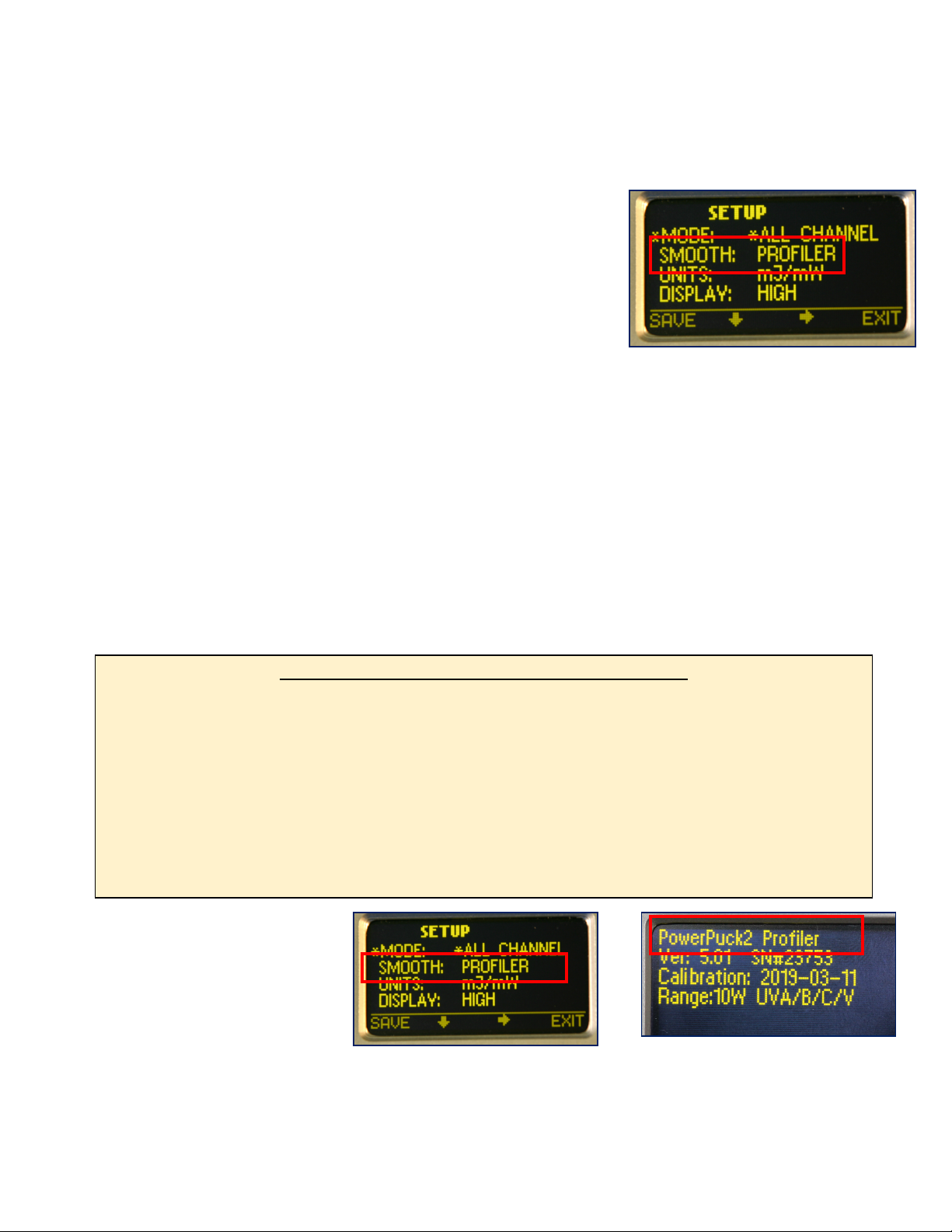
Right: Display referring to SMOOTH
PROFILER (Sample Rate)
Far Right: PROFILER Enabled
Instrument
“SMOOTH” PROFILER vs. PROFILER “INSTRUMENTS”
EIT uses the term “PROFILER” to describe two separate instrument features.
When PROFILER is used in the “SMOOTH” context, it refers to an effective sample rate of 128 Hz as
described above.
When PROFILER is used in the “INSTRUMENTS” context, it refers to instruments (Power Puck II Profiler,
UviCure Plus II Profiler, LEDCure Profiler) that have the ability to transfer the irradiance profile (Watts/cm
2
as a function of time) to a computer for further analysis.
Profiler enabled “INSTRUMENTS” can be identified in the first line of the start-up screen.
Please see Appendix C for more information on PROFILER enabled instruments

EIT Part Number P/N IM-0111 Rev A Issued April 2019
Page 13
Diagnostics & Error Messages
The UV Power Puck II and UVICURE Plus II continuously conduct internal self-diagnostics. If the unit detects an
internal problem, it will display one or more of the following error codes in the upper left corner on the display. Error
codes are two alphanumeric characters preceded by an *. If two errors are experienced at the same time, both error
codes will flash alternately on the screen every 0.5 seconds. Certain error codes may indicate problems that require
returning the unit to the factory for service.
Low Battery Indicator
*LB – Low Battery
If this happens during an exposure run, the reading is still valid. The low battery indicator is designed to illuminate
early enough so that your data remains valid. Under severe low battery conditions, the unit does not operate.
Therefore, confirm that the unit flashes “RUNNING” before initiating a reading.
Over-Temperature State
*OT – Over Temperature
If the internal temperature of the UV Power Puck® or UVICURE Plus exceeds 65
o
C during an exposure run, the unit
will emit a steady beeping tone after the run. However, the data it has collected is accurate and can be read by
pressing the Select button. When doing this, the beeping tone stops and you can scroll through the data readings. In
addition, if the internal temperature of the unit exceeds 75
o
C, the unit beeps once then displays the internal
temperature continuously. The unit will not operate until the internal temperature drops below 75
o
C. The maximum
internal temperature is 80°C. If the internal temperature exceeds 80°C, the warranty is voided. CAUTION: If you
press the Reset button to initiate the RUN mode before the unit cools to 75
o
C, all data from the previous exposure run
is cleared from memory. The unit beeps and again continuously displays the temperature.
Over Range State
*OR – Over Range
The over range error message will be displayed if the peak irradiance value is too large for the instrument to measure.
Note that a unit’s full scale range will be marginally higher than the normal range. Readings that exceed the nominal
range and do not result in an *OR error are valid.
Suggested Operating Ranges for Power Puck II and UviCure Plus II
•10 Watt Standard (High- H) Range:
oUVA, UVB, UVV - 100mW/cm² to 10W/cm²
oUVC - 10mW/cm² to 1W/cm²
•1 Watt Mid (M) Range:
oUVA, UVB, UVV -10mW/cm
2
to 1W/cm
2
oUVC: 1mW/cm
2
to100mW /cm
2
•100 milliWatt Low (L) Range:
oUVA, UVB, UVV - 1mW/cm² to 100mW/cm²
oUVC - 1mw/cm
2
to 100mW/cm
2
Other Error Codes
For all other error codes, please call EIT for disposition.
EIT Part Number P/N IM-0111 Rev A Issued April 2019
Page 14
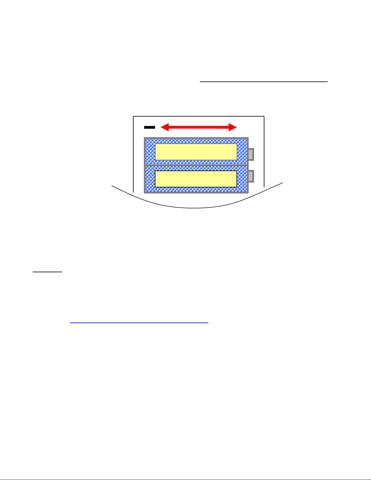
Replacing the Batteries
The UV Power Puck II or UVICURE Plus II should be turned OFF.
1. Loosen the screw on the battery door and remove the door.
2. Remove the old batteries and dispose of them properly.
3. Install two new AAA size alkaline cells, observing polarity. Both cells are installed in the same direction.
4. The proper direction is indicated on the PCB and on the housing inside the battery compartment. The unit is
designed so it will not operate with reversed cells.
5. Replace the door and the screw.
Maintenance – Cleaning and Calibration
Cleaning-Display
Use a soft cloth to clean the display window. If needed, the use of Isopropyl Alcohol is acceptable.
WARNING - DO NOT USE ACETONE TO CLEAN THE DATA DISPLAY SCREEN AS IT WILL DAMAGE THE
DISPLAY.
Cleaning-Optics
Use caution when touching the optics surface of the instrument.
To clean the optical surface, refer to the detailed Optics Cleaning Instructions provided in Appendix A or on
our website: https://www.eit.com/products/care-and-cleaning
Calibration
EIT’s calibration period for the Power Puck II or UviCure Plus II is six months. This based on our historical data and
experience. This data is a culmination of over twenty years of calibration experience. Most of these units are exposed
to extreme environmental conditions and though they are very robust; the opportunity for error climbs higher, over a
prolonged period of time.
EIT does not know how many times the instrument will be used each day, power of lamps, application conditions such
as heat and how the instrument will be handled, cleaned and stored.
An individual company based on the feedback they receive from EIT or an EIT Authorized Service can elect to set their
own internal calibration interval. If you desire to extend the cycle on your own behalf; it is your privilege to do so.
Many internal quality processes allow for the unit owner to determine through historical data, frequency of use, etc. to
extend the cycle if it is warranted. In fact ISO 9001 section 7.6 (Control of monitoring and measuring devices) states
-
SIZE AAA ALKALINE
+
-
SIZE AAA ALKALINE
+
+

EIT Part Number P/N IM-0111 Rev A Issued April 2019
Page 15
your organization can adjust or re-adjust as necessary your calibration cycles as long as it is consistent with the
monitoring and measurement requirements of your process.
Returning an Instrument to EIT Instrument Markets
You do not need to contact EIT before returning your unit.
Please include a Service Request Form in each shipment sent to EIT.
Service Request Forms can be found on our website (www.eit.com) under EIT UV Products and then
Customer Service and Support.
When returning the UV Power Puck II or UviCure Plus II, please return the equipment in the original (or equivalent)
packaging. You will be responsible for damage incurred from inadequate packaging, if the original packaging is
not used.
The customer is responsible for insuring the unit during transportation to EIT.
Please see our Warranty Policy below. Equipment repaired under warranty will be returned to the user with no
charge for the repair or shipping. EIT will notify you of repairs not covered by warranty and their cost prior to
performing any work on the equipment.
EIT reserves the right to make changes in design at any time without incurring any obligation to install the same on
units previously purchased.
Address for Returning All Instruments to EIT
Ship the unit, freight prepaid, to the address below:
EIT LLC
Attention: Service Department
309 Kelly’s Ford Plaza SE
Leesburg, VA 20175 USA
Include a Service Request Form with your shipment which has your contact information.
EIT will contact you if any additional information is needed.

EIT Part Number P/N IM-0111 Rev A Issued April 2019
Page 16
EIT UV Instrument New Product and Calibration/Repair Warranty
New Product Warranty
Electronic Instrumentation and Technology LLC (EIT) warrants that all goods described in this manual (except
consumables) shall be free from defects in material and workmanship. Such defects must become apparent within
six months after delivery of the goods to the buyer.
EIT’s liability under this warranty is limited to replacing or repairing the defective goods at our option. EIT shall
provide all materials and labor required to adjust, repair, and/or replace the defective goods at no cost to the buyer
only if the defective goods are returned, freight prepaid, to EIT during the warranty period.
EIT shall be relieved of all obligations and liability under this warranty if:
1. The user operates the device with any accessory, equipment, or part not specifically approved or
manufactured by EIT, unless the buyer furnishes reasonable evidence that such installations were not a
cause of the defect. This provision shall not apply to any accessory, equipment, or part that does not
affect the proper operation of the device.
2. Upon inspection, the goods show evidence of becoming defective or inoperable due to abuse,
mishandling, misuse, accident, alteration, negligence, improper installation, lack of routine maintenance,
or other causes beyond our control.
3. The goods have been repaired, altered, or modified by anyone other than EIT or EIT authorized
personnel.
4. The buyer does not return the defective goods, freight prepaid, to EIT within the applicable warranty
period.
There are no warranties that extend beyond the description on the face hereof. This warranty is in lieu of - and is
exclusive of - any and all other expressed, implied, or statutory warranties or representations. This exclusion includes
merchantability and fitness, as well as any and all other obligations or liabilities of EIT. EIT shall not be responsible for
consequential damages resulting from malfunctions of the goods described in this manual.
No person, firm, or corporation is authorized to assume for EIT, any additional obligation or liability not expressly
provided for herein except in writing duly executed by an officer of EIT.
If any portion of this agreement is invalidated, the remainder of the agreement shall remain in full force and effect.
This warranty shall not apply to any instrument or component not manufactured by EIT.
Calibration/Repair Warranty
EIT will warranty calibration and/or repair services just performed, for 90 days. This Calibration and Repair Warranty
does not apply to nor cover repairs that may otherwise occur to the instrument. Such repairs may be covered under
the New Product Warranty based on the age of the instrument.
EIT Part Number P/N IM-0111 Rev A Issued April 2019
Page 17
Appendix A: Optics Cleaning
Display Cleaning Instructions
Use of a Soft Cloth is recommended for Cleaning the Display Window. If needed, use of Isopropyl Alcohol is
acceptable.
WARNING – DO NOT USE ACETONE TO CLEAN THE DATA DISPLAY SCREEN. IT MAY DAMAGE THE DISPLAY.
Optics Cleaning Guidelines
Guidelines and a video on cleaning are posted on our website at:
www.eit.com/products/care-and-cleaning
EIT radiometers are used to design, measure and control industrial UV
applications in a wide variety of locations. The environmental conditions that our
instruments are exposed to vary from pristine (medical clean room) to challenging
(wood manufacturing facility). Careful cleaning of the outer optics using these
guidelines will help your EIT instrument perform as designed between service
intervals at EIT. The guidelines are general and specific questions should be
dropped, get stuck in equipment or wind up covered or immersed with the product
being cured need to come back to EIT for further evaluation.
General Cleaning Guidelines
1. Establish an area for cleaning with the necessary supplies.
2. Avoid cleaning the optics with anything dry or abrasive such as a cloth, towel
or clothing.
3. Fingerprints, oils from your hands, lint, dust, or contamination on the optics
window usually increases the UV values reported.
4. Scratches to the metallic coating on optics window also most often cause the
readings to increase.
5. There are two cleaning methods (Wipes, Swabs) described on this Guide.
Select the one that best suits your needs and train your staff on these
techniques.
6. Further information including a link to videos showing these techniques can
be found on the EIT web site at: www.eit.com/products/care-and-cleaning
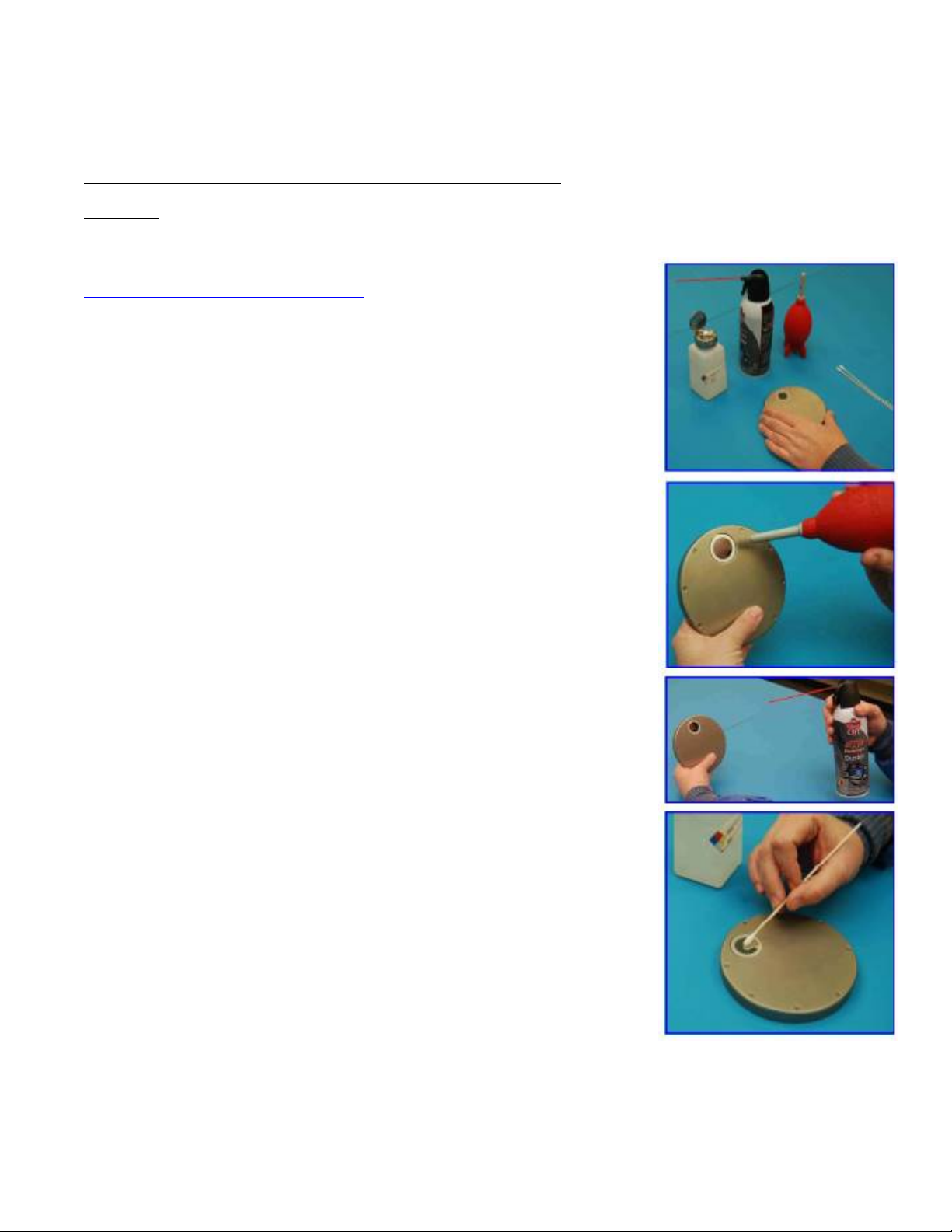
Steps For Cleaning with Swabs and Isopropyl Alcohol (IPA)
1. Examine the instrument to determine if it needs cleaning.
2. Carefully blow or brush loose particles away from the optics. Handheld bulbs
to blow air are available from camera stores.
3. If needed, use “canned air” in very short (< 1 second) bursts from 8-10 inches
or more away from the optics. Short bursts from a distance will minimize the
transfer of any additives from the ‘canned air’ to the optics. If using
compressed air, make sure it is oil free, “instrument grade” air.
4. Plan to use a minimum of two lint free swabs to clean the optics. The first
swab, once moistened with the IPA is used to gently apply the IPA solution in
a circular motion.
5. Rotate the swab between your fingers as you work your way around the
optics window in a circular fashion.
6. No double dipping-do not put this swab back into the IPA. Discard it to
prevent contamination of the IPA from any material picked up from the optics.
Use a clean swab if additional IPA is needed.
7. Use a clean swab in a gentle circular motion to dry the IPA on the optics.
Again rotate the swab between your fingers as you gently move it over the surface. Stop when the majority of the
IPA has been absorbed by the swab. Properly dispose of the swabs.
8. Repeat steps 4 and 5 if needed using new swabs.

EIT Part Number P/N IM-0111 Rev A Issued April 2019
Page 18
Hints
1. Label the IPA as required & follow the Safety Data Sheet (SDS) for IPA. Consider a dedicated IPA dispenser to
avoid cross contamination from other activities.
2. Do not use IPA with detergents or other additives.
3. Use lint free cotton swabs. If you see streaking, consider another brand of cotton swab.
4. If you “double dip” by inserting a used swab into your IPA, the IPA can be compromised from material transferred
from the instrument optics via the swab. Glue holding the cotton to the applicator stick may also be dissolved by
the IPA and transferred to the IPA.
Steps For Cleaning with Instrument Wipes
EIT has sourced an industrial grade wipe that can be used for cleaning the optics on
our UV measurement products. The Instrument Wipe contains a fast evaporating,
mild solvent for cleaning EIT optics. The wipe is non-linting, non-abrasive and does
not contain any detergents or surfactants that can harm the optics. Each wipe stays
sealed until used to prevent contamination of the cleaning solution.
1. Examine the instrument to determine if it needs cleaning.
2. Carefully blow or brush loose particles away from the optics. Handheld bulbs to
blow air are available from camera stores.
3. If needed, use “canned air” in very short (< 1 second) bursts from 8-10 inches or
more away from the optics. Short bursts from a distance will minimize the transfer
of any additives from the ‘canned air’ to the optics. If using compressed air, make
sure it is oil free, “instrument grade” air.
4. EIT suggests the use of gloves to prevent the transfer of oils from your hands to
the wipes and possibly to the optics of the instrument. Handle the gloves from the
wrist and not the part of the glove that will hold the wipe.
5. Once the sealed package is opened, the wipe can be unfolded and the optics
cleaned with a gentle circular motion. We suggest bunching a small section of the wipe to start.
6. Move to different areas of the cloth wipe and bunch new sections as you clean. The Wipe is large enough that you
may be able to clean multiple instruments. Properly dispose of the wipe
Hints
1. EIT strongly suggests the use of gloves to prevent the transfer of oils from your hand to the optics on the unit.
2. Each wipe is fresh and ready for use. The IPA in the wipe does not contain any detergents or surfactants and is
not subject to being compromised from a cleaning of a previous instrument and/or other use in your facility.
3. The Safety Data Sheet (SDS) for EIT Instrument Wipes is posted on our website (www.eit.com) under UV
Products. There is also a link to a video showing the cleaning technique with the Wipes.
4. EIT Instrument Wipes are available for purchase in boxes of 50
Additional information and detailed instructions about cleaning can be found on the EIT web site at:
www.eit.com/products/care-and-cleaning
This manual suits for next models
1
Table of contents
Other EIT Measuring Instrument manuals


