eKey CV WIEG User manual

ekey home
OPERATING INSTRUCTIONS
en 01

en│1
English
Translation of the original instructions –ID159/271/0/135
Table of contents
General ..........................................................................................2
Note ...........................................................................................2
Product liability and limitation of liability .........................................2
Warranty and manufacturer'swarranty ............................................2
Notices, symbols and abbreviations...............................................2
Safety information .........................................................................3
Life-threatening danger resulting from electricity .............................3
Safety against tampering ..............................................................3
Product description .......................................................................4
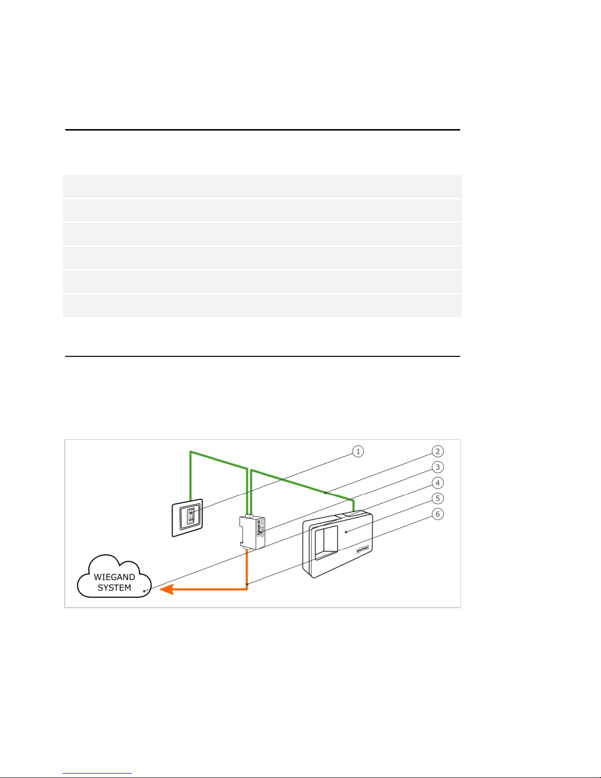
System overview..........................................................................4
Scope of delivery..........................................................................4
Proper use and area of application..................................................4
Wiegand converter .......................................................................5
Configuration tool.........................................................................6
Technical specifications .................................................................7
System setup variants ...................................................................7
variant........................................................................7ekey home
variant 1 .....................................................................8ekey multi
variant 2 .....................................................................8ekey multi
Converter configuration.................................................................9
Preparing for configuration ............................................................9
Carrying out the configuration ..................................................... 11
Configuration examples............................................................... 13
Installation and implementation..................................................15
Resetting default settings............................................................16
Maintenance ................................................................................16
Dismantling and disposal.............................................................16
Declaration of conformity ............................................................16
Copyright.....................................................................................16

2│en
General
ekey biometric systems GmbH operates a quality management system in
compliance with EN ISO 9001:2008 and is certified accordingly.
This manual forms a component of the product. Ensure that it is stored in
a safe place. Please contact your dealer for further information about the
product.
Safe operation and function of the machine can be impaired in the
following situations. Liability due to malfunctioning is transferred to the
operator/user in such cases:
□The system devices are not installed, used, maintained and
cleaned in accordance with the instructions;
□The system devices are not used within the scope of proper use;
□Unauthorised modifications are carried out on the system
devices by the operator.
These operating instructions are not subject to updating. Subject to
optical and technical modifications, any liability for errors and misprints
excluded.
Our general terms and conditions apply as valid at the date of purchase.
http://www.ekey.net/files/AGB/dtAGB.pdf.
ekey biometric systems GmbH provides a 24-month warranty for material
or processing defects. This warranty is only valid in the country where the
product was purchased. The product may only be used with original ekey
spare parts and accessories.
Notices, symbols and abbreviations
NOTICE
Denotes additional information and useful tips.
DANGER
Denotes imminent danger which could lead to death or serious
injuries.
ATTENTION
Denotes possible property damage which cannot result in injuries.
Note
Product
liability and
limitation of
liability
Warranty and
manufacturer'
s warranty

en│3
Symbols:
1.
Step-by-step instructions
Reference to sections of this manual
Reference to the mounting instructions
Reference to the wiring diagram
□
Listing without specified order, 1st level
ekey home FS UP
Product names
MENU ITEM
Menu items
Button
Buttons
Abbreviations:
CV
Converter
OEM
Original Equipment Manufacturer
WIEG
Wiegand
Safety information
DANGER
All devices are to be operated with safety extra-lowekey home
voltage (SELV). Only use power supplies rated protection class 2
according to VDE 0140-1.
Failure to do so will result in life-threatening danger due to
electric shock.
Only certified electricians are authorised to carry out the electrical
installation!
Mount the converter in a safe internal area. This prevents tampering from
the outside.
Life-
threatening
danger
resulting from
electricity
Safety against
tampering

4│en
Product description
Fig. 1: Overview of the system
1Third-party Wiegand system
2ekey RS485 bus
3Power supply
4Control panel
5Wiegand converter
6Distributor
7Motorised lock
8Cable transfer
9Finger scanner
□Wiegand converter;
□Mounting set;
□Operating instructions, mounting instructions and wiring
diagram;
□Optional: Finger scanner, control panel, USB converter, software
CD, cable transfer, power supply, connection cable, covers,
etc.).
This product is an accessory for a finger scan access control system. The
device is integrated into the system. The system is comprised of a finger
scanner, control panel, converter and third-party Wiegand system. It is
available in various makeups and component combinations. The converter
converts the internal ekey RS485 protocol to a Wiegand protocol. Data is
transmitted in one direction from the system toekey home or ekey multi
the third-party Wiegand system, and never the other way round.
The system is used to establish a data connection between the ekey home
or system and a third-party Wiegand system.
ekey multi
System
overview
Scope of
delivery
Proper use
and area of
application

en│5
Function of the converter
The converter reads out the sent information at the ekey RS485 bus. It
converts this data into a predefined Wiegand protocol. The converter
sends the generated data to the third-party Wiegand system for further
processing. The predefined data format can be adapted to the third-party
system using the configuration tool and a USB converter.
Controls and visual signals on the converter
1Status LED
2Button
Fig. 2: Overview of
ekey home CV
WIEG RS485
The converter has a status LED for displaying operating statuses. There is
a button for resetting the device to its default settings.
Button operation
Function
Press and hold button for 4
seconds.
Resets default settings.
Table 1: Button operation of ekey home CV WIEG RS485
Display
Description
Status LED flashes green.
Normal mode.
Status LED lights up green.
Data is being sent.
Status LED flashes red.
Default setting/
incorrect connection.
Table 2: Visual signals for ekey home CV WIEG RS485
Wiegand
converter

6│en
Wiegand protocol
The converter is delivered from the factory with the widely-used 26-bit
Wiegand format. The binary Wiegand ID is comprised of even parity,
facility code, user ID and odd parity.
Bit assignment: P FFFFFFFF UUUUUUUUUUUUUUUU P
Letter
Name
Bit length
Binary code
P
Even parity
1
0-1
F
Facility code
8
0-255
U
User ID
16
0-65535
P
Odd parity
1
0-1
Table 3: 26-bit Wiegand format
Parity
The parity bit is used to check the sent data.
Facility code (unique device code)
The facility code uniquely defines the finger scanner in the third-party
Wiegand system. The default code is 1. The code can be changed using
the configuration tool.
User ID (unique user number)
The user ID is made up of the user number and the finger number. In an
system, this is calculated as follows:ekey home
User ID * 10 + finger number
e.g.: User number 15 with finger number 7: 15 * 10 + 7 = 157
In an system, the user ID is calculated as follows:ekey multi
(User ID - 1) * 10 + finger number
e.g.: User number 15 with finger number 7: (15 - 1) * 10 + 7 = 147
You can change the length of the Wiegand ID using the configuration tool.
An additional OEM code can also be defined during configuration. This is
added before the facility code.
The configuration tool is integrated in the software. Thisekey FWupdate
can be found on the CD supplied with the and is alsoekey converter USB
available to download from the ekey homepage. Click on the following link
to go to the download area:
http://www.ekey.net/downloads/cat/Software.
NOTICE
An is required in order to establish a connectionekey converter USB
between the Wiegand converter and the PC.
Configuration
tool

en│7
Function of the configuration tool
The configuration tool is used to configure the converter. The ID is
entered in decimal values.
Software requirement
The software only operates on MS Windows operating systems.
Technical specifications
Description
Unit
Value
Supply
VAC/VDC
8-24/8-30
Power input
W
approx. 1
Temperature range
°C
-25 to+70
Baud rate at RS485
Bd
115200
Protection class
IP
20
Table 4: Technical specifications: ekey home CV WIEG RS485
System setup variants
There are three setup variants for connecting an orekey home ekey multi
system to a third-party Wiegand system.
Fig. 3: Overview of the variantekey home
1Finger scanner
2ekey RS485 bus
3Wiegand converter
4Third-party Wiegand system
5Control panel
6Wiegand connection cable
The variant comprises a finger scanner, a control panel, aekey home
converter and a Wiegand interface to the third-party system. The
converter transmits the sent data from the finger scanner to the third-
party Wiegand system.
ekey home
variant

8│en
Fig. 4: Overview of variant 1ekey multi
1Finger scanner 1-4
2Third-party Wiegand system
3Wiegand connection cable
4ekey RS485 bus
5Wiegand converter
6Control panel
variant 1 comprises up to four finger scanners, a control panel,ekey multi
a converter and a Wiegand interface to the third-party system. The
converter transmits the sent data from each finger scanner to the third-
party Wiegand system. With this system setup, the converter is connected
to a Wiegand interface for the third-party system. The third-party system
must therefore be able to recognise various facility codes.
Fig. 5: Overview of variant 2
ekey multi
1Finger scanner 1-4
2Wiegand converter 1-4
3Third-party Wiegand system
4ekey RS485 bus
5Wiegand connection cable 1-4
6Control panel
variant 2 comprises up to four finger scanners, a control panelekey multi
and the same number of converters and Wiegand interfaces to the third-
party system as there are finger scanners. Each converter transmits the
sent data from one finger scanner to the third-party Wiegand system.
With this system setup, the individual converters are connected to
different Wiegand interfaces for the third-party system.
ekey multi
variant 1
ekey multi
variant 2

en│9
Converter configuration
NOTICE
In an system, the converter only needs to be configured if aekey home
26-bit Wiegand format cannot be used.
NOTICE
In an system, the converter must be configured, as theekey multi
individual finger scanners require a unique facility code. Configuration is
not absolutely essential in the following system setups if a 26-bit Wiegand
format can be used:
□Only one finger scanner is used in the system;
□Only one converter is used in the system and a
distinction between the individual finger scanners does not need to
be made in the third-party Wiegand system. ( variant 1)ekey multi
The following components are required to configure the converter:
□;ekey converter USB
□USB connection cable;
□RS485 connection cable;
□Power supply;
□PC with MS Windows operating system and USB-2.0 interface;
□software with configuration tool.ekey FWupdate
If you have already implemented your system, disconnect it from the
power supply. Dismantle the toekey home converter Wiegand RS485
enable it to be configured.
Preparing for
configuration

10│en
Fig. 6: Wiring diagram for configuring the converter
1PC with MS Windows operating system
2USB converter
3Wiegand converter
4RS485 connection cable
5USB connection cable
6Power supply
Cable the devices according to the wiring diagram (Fig. 6).
ATTENTION
The device connections are not polarity reversal protected!
Possible property damage!
Check the configuration of the wires carefully before connecting the power
supply.
Step
Instruction
1.
Install the software on your PC.
ekey FWupdate
2.
Connect the USB connection cable to the PC.
3.
Wait until the USB driver has been installed.
4.
Connect the power supply to the mains.
The devices are ready for configuration.

en│11
You can use the configuration tool to make changes to the Wiegand
protocol. The following aspects can be changed:
□The OEM code
□The facility code
□The length of the user ID and the facility code
Prepare the devices for configuration.
See Preparing for configuration, page 9.
Step
Instruction
1.
Launch the software.
ekey FWupdate
2.
The program automatically opens with the
ekey FWupdate
update window.
NOTICE
This function enables you to download the most recent
firmware software for your products. Once you have
downloaded it to your PC, you can use these files for an
update.
3.
If you require an update: Select the required products.
Then click on Start.
If you do not require an update: Click on End.
4.
The start screen is displayed.
Carrying out
the
configuration

12│en
Step
Instruction
5.
Select the connected from the
ekey converter USB
dropdown menu based on the serial number.
6.
Click on Search.
7.
The connected is
ekey home converter Wiegand RS485
listed. The Wiegand button is enabled.
8.
Click on Wiegand.
9.
The input screen for the Wiegand protocol is displayed.

en│13
Step
Instruction
10.
Enter the required values in the input fields.
NOTICE
For a system setup with several converters (
ekey multi
variant 2), input field FS1 must always be used for the
finger scanner assignment.
This means that the serial number of the finger scanner
being assigned and the corresponding facility code must be
entered in the FS1 input line for each converter.
11.
Click on Save to apply the settings.
Click on Cancel to discard the settings.
Configuration of the converter is complete. The converter is ready for
installation and implementation.
Below you will find configuration examples for the different system setup
variants.
variantekey home
In this example, the 26-bit Wiegand format was adapted to the third-
party Wiegand system. The OEM code and bit lengths were configured.
Fig. 7: Configuration example: variantekey home
variant 1ekey multi
In this example, the serial numbers of the 4 finger scanners being
assigned and the facility codes in the converter have been entered. This
Configuration
examples

14│en
configuration means that the finger scanners are uniquely defined in the
third-party Wiegand system. The 26-bit Wiegand format was not changed.
Fig. 8: Configuration example: variant 1ekey multi
variant 2ekey multi
In this example, the serial numbers of the 4 finger scanners being
assigned and the facility codes in the 4 converters being used have been
entered in input line FS1. This configuration means that the finger
scanners are uniquely defined in the third-party Wiegand system. The 26-
bit Wiegand format was not changed.
Fig. 9: Configuration example: variant 2ekey multi

en│15
Installation and implementation
ATTENTION
Mount and cable the product correctly before connecting the power.
Possible property damage!
Do not connect the power supply beforehand!
Mount the system in accordance with the supplied mounting instructions.
Cable the system in accordance with the supplied wiring diagram.
Step
Figure
Description
1.
-
Ensure safe installation of the devices. Close the
covers.
2.
-
Connect the power supply to the mains.
3.
The status LED flashes red: incorrect connection.
4.
The status LED flashes green: Normal mode.
5.
-
If the LEDs fail to light up, check the wiring and
power supply.
The system has been installed and implemented. The data connection
between the two systems has been established. The system is ready for
use.
NOTICE
For information regarding the further processing of the sent Wiegandekey
data in the third-party Wiegand system, refer to the documents provided
by the supplier of your Wiegand system.

16│en
Resetting default settings
Resetting the default settings deletes the configured Wiegand protocol.
The default 26-bit Wiegand format with facility code 1 is used again.
Step
Action
Description
Display
1.
Press and hold the button
with the operating rod for
at least 4 seconds.
Status LED
flashes red.
The converter has been reset to its default settings. You can now
recommission the system.
Maintenance
The system is largely maintenance-free.
Dismantling and disposal
Pursuant to Directive 2002/96/EC of the European Parliament and Council
of 27 January 2003 on the sale, return and environmentally friendly
disposal of electrical and electronic equipment (WEEE) supplied after
13/08/2005, electrical and electronic equipment is to be recycled and may
not be disposed of with household waste. As disposal regulations within
the EU can differ from country to country, please contact your dealer for
further information as necessary.
Declaration of conformity
ekey biometric systems GmbH hereby declares that the product conforms
to the relevant provisions of the Electromagnetic Compatibility Directive
2004/108/EC of the European Union. The complete text of the declaration
of conformity can be downloaded from
http://www.ekey.net/downloads/cat/Zertifikate.
Copyright
Copyright © 2013 ekey biometric systems GmbH.
All content, artwork and any ideas contained in these operating
instructions are subject to applicable copyright laws. Any transmission,
relinquishment or transfer of this content or parts thereof to any third
party requires the prior written consent of ekey biometric systems GmbH.
Original documentation.

www.ekey.net
ID 159/271/0/135: Version 1,
24.09.2013
Made in Austria
Austria
ekey biometric systems GmbH
Lunzerstraße 89, A-4030 Linz
Tel.: +43 732 890 500 2500
offi ce@ekey.net
Switzerland & Liechtenstein
ekey biometric systems Est.
Landstrasse 79, FL-9490 Vaduz
Tel.: +41 71 560 54 80
offi ce@ekey.ch
Italy
ekey biometric systems Srl.
Via del Vigneto, 35/A, I-39100 Bolzano
Tel.: +39 0471 922 712
italia@ekey.net
Germany
ekey biometric systems Deutschland GmbH
Liebigstraße 18, D-61130 Nidderau
Tel.: +49 6187 906 960
deutschland@ekey.net
Eastern Adriatic region
ekey biometric systems d.o.o.
Vodovodna cesta 99, SLO-1000 Ljubljana
Tel.: +386 1 530 94 89
info@ekey.si
This manual suits for next models
1
Table of contents
Popular Control Unit manuals by other brands

oventrop
oventrop Oilstop V operating instructions

DAZE
DAZE Dynamic Power Manager installation manual

Espressif Systems
Espressif Systems ESP32-S3-WROOM-2 user manual

Pittway
Pittway SYSTEM SENSOR M500FP Installation and maintenance instructions

NCR
NCR personaS84 ATM Operator's manual

Honeywell
Honeywell 5496 manual

National Instruments
National Instruments NI 9227E Operating instructions and specifications

Toa
Toa ZM-9001 operating instructions

Emerson
Emerson ALCO Thermo TX6 installation instructions

MSA
MSA Cylinder Valve Maintenance and Repair

Mosaic
Mosaic URC 9950 user guide

Rockwell Automation
Rockwell Automation Allen-Bradley Guard I/O DeviceNet 1732DS-IB8 user manual