Ekin Endustriyel GemmeCotti HTM Series User manual

GemmeCotti
User Guide

www.twitter.com/ekinendustriyel
www.facebook.com/ekinendustriyel
www.youtube.com/ekinendustriyel
www.linkedin.com/company/ekinendustriyel
www.instagram.com/ekinendustriyel
Follow us on social media!

Sustainable Innovation,
Quality Standardization and Dynamism
Ekin has entered Turkey’s sector of the imported plate heat exchanger, with their customerfocused
vision and dynamic. Ekin has expanded into new and upcoming investments. One of the main
steps was gaining the identity of being a producer. Ekin has started the production of plate heat
exchangers with the brand of “MIT”. We have grown in the philosophy of quality, through initially
adapting to ISO Quality Management.
MIT plate heat exchangers have now become a solution to engineering problems in the world
market and have grown through an expansion of franchises.
Engineering Approaches, Integrated Solutions
Ekin has expanded into the production of components, sales, and after-sales service by employing
expert engineers. The factors that guided Ekin to success are their exceptional customer service
to the needs and wants of consumers, modern facilities, and becoming partners to projects that
involve high-end technology.
Ekin is an expert company which has a wide product range which includes plate heat exchangers,
accumulation tanks, water heater tanks, installation, and its service group and submit competitive
advantages to mechanical installation sector in Turkey and all around the world.
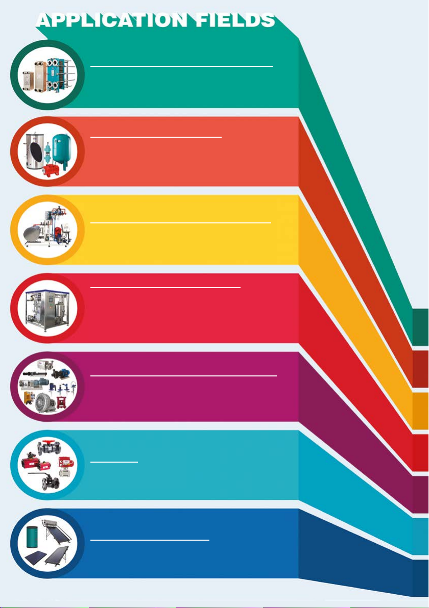
HEAT TRANSFER PRODUCTS
PRESSURE VESSELS
COMPLETE SYSTEMS UNITS
FLUID TRANSFER PRODUCTS
VALVES
ENERGY SYSTEMS
FOOD GRADE SYSTEMS
• Gasketed Plate Heat Exchangers • Brazed Heat
Exchangers • Shell&Tube Heat Exchangers • Air Fan
Oil Cooler • Economizers • Coils and Radiators
• Water Heater Tanks • Water Storage Tanks • Buffer
Tanks • Expansion Tanks • Stainless Steel Process
Tanks • Balance Tanks / Dirt Separators / Air Separators
• Pressured Air Tanks • Neutralization Tanks • Air Tubes
• Steel IBC Tanks with ADR
• Heat Stations • Steam Package Systems
• Special Designed Systems • Dosing Systems
• Substations • Thermoregulators
• Lobe Pumps • Hygienic Centrifuge Pumps • Turbo /
Roots / Centrifuge Blowers • Drum Pumps • Acid Pumps
• Dosing Pumps • Monopumps • Air Operated Double
Diaphragm Pumps (AODD)
• Thermoplastic Valves
• Plastomatic Valves
• Solar Collectors
• Water Heater Tanks For Solar
• Pasteurizers with plate heat exchangers • Hygienic
Pasteurizers with Shell & Tube Heat Exchangers
• Cheese and Whey Systems • UHT - Sterilization Systems
• CIP Systems • Hygienic Storage and Process Tanks
• Homogenizers • Standardization Systems • Evaporators
• Turn-key Projects

1. Introduction ...............................................................................................................................1
2. Installation ............................................................................................................................... 2
3. Operation ................................................................................................................................. 8
4. Maintenance........................................................................................................................... 12
5. Problem Solutions ................................................................................................................. 18
6. Spare Parts ............................................................................................................................ 18
7. Data ....................................................................................................................................... 19
CONTENTS

1
1. INTRODUCTION
1.1 General
This manual refers to mag drive centrifugal pumps of HTM series. Pumps of series HTM are made
of thermoplastic materials (Polypropylene or PVDF) and can be of different sizes.
1.3 Warning Symbols For Safe
1.2 Purpose of The Manual
The main purpose of this manual is to assure that the activities of installation, operation and
maintenance of the pumps are executed in a correct and safe way by all the personnel in charge
of these operations.
Keep this manual in a safe place for future consultations.
This symbol indicates a possible danger caused by the presence of electrical elds,
contacts or wires with electric current.
All the symbols with the exclamation mark indicate an important situation that needs
the attention of the personnel. In particular, these are indications useful for the correct
functioning and prevention of possible damage to the equipment.
This symbol indicates the presence of strong magnetic elds which can damage or
compromise the functioning of other equipment nearby.
This symbol signals a danger or a situation that requires the maximum attention of the
personnel. It’s important to respect the instructions stated at the margin of this symbol
and proceed very carefully. It’s necessary to inform all the personnel and/or users that
the rules indicated prevent injuries.
1.4 Qualication and Training of The Personnel
Those in charge of the installation, operation and maintenance of the pumps have to be
qualied to carry out the actions indicated in this manual. Ekin Endüstriyel is not
responsible for the inadequate qualication and training of the customer’s staff or for
the lack of information of the staff regarding the contents of this manual. It’s compulsory
to always show this manual to the workers in charge of the installation, operation and
maintenance of the pump.

2
Preliminary Remarks
All the references to the pumps have to be considered applicable also to systems that use these
pumps unless it’s specied otherwise.
2.1 Safety General Warnings1
2.1.1 Introduction About Danger
1.5 Explosive Atmosphere Zones
HTM PP/PVDF pumps CANNOT be used in explosive atmospheres. These uses require special
pumps that GemmeCotti manufactures with particular materials and precautions. Customers who
want to use special pumps in these kind of zones have to contact the Ekin Endüstriyel technical
ofce for the correct choice of the product. The pumps, manufactured by GemmeCotti, for these
kind of applications belong to the series EM-C or EM-T or EM-P. Pump model EM-C, EM-T e EM-P
in PP or PVDF can be used only for Atex zone2, II3G. Please refer to paragraph 2.7.1 for further
instructions.
We remind you that the classication of the zone (Ref. Atex 2014/34/EU former 94/9/CE
directive) for potentially explosive atmoshpere zones have to be done by the customer
and communicated to GemmeCotti for the right choice of the kind of pump suitable to
work in these zones.
Furthermore, the customer is responsible of the correct installation of the pump in accordance
with the requirements stated in the directive.
2. INSTALLATION
The non-observance of the indications stated in this manual or the inappropriate use of
the equipment by unqualied or unauthorized staff, can cause serious personal injuries
or death and damages to products and apparatus!
1 If these warnings are not observed the certication and the warranty of the pump can be invalidated.
2.1.2 Indications of Danger
For the safety of those in charge of the installation of the pump it’s necessary to use
safety clothing and individual safety devices approved by the current provisions of the
law (e.g. safety glass, gloves and safety insulating-shoes)

3
The pump contains particularly powerful magnets. It’s forbidden for those who have
cardiac pacemakers, debrillators, electronic medical devices, metallic heart valves,
metallic prosthesis or sickle cell anaemia, to handle or be in the proximity of the
magnets contained inside the pumps. Consult a health care provider for specic
recommendations before working with these pumps.
The powerful magnetic elds in the proximity of the pumps can damage heart
pacemakers, watches, credit cards, discs and magnetic tapes inside calculators and
computers.
When working in the proximity of pumps, consider that the devices or metallic parts that
you are handling can be unexpectedly attracted towards the pump causing possible
crushing of ngers or hands.
These pumps have been designed and manufactured to be used in specic conditions
and within dened limits. The use outside these specications has to be agreed and
approved by the Ekin Endüstriyel technical service. It must be considered also that,
if the pumps are used outside their technical specications, the CE Certications and
the warranty are no longer valid. Furthermore, if the pump is used outside the technical
specications communicated to us at the moment of the quotation and conrmed in
our order conrmation, the customer becomes responsible for the issue of a new CE
Certication.
The pump has to be used only for the applications specied in the order for which
GemmeCotti has selected the model, the materials of construction and has tested the
pump to respect the specications. For other uses different from those stated in the
order, customer has to call the Ekin Endüstriyel technical ofce.
There will not be any warranty for repairs or alterations on the product done by the
users or third parties not specically authorized by Ekin Endüstriyel. Always shut down
the pump before touching or proceeding with any intervention on it or on the circuit
of installation. The pump must be empty of pumped liquid and it must be completely
decontaminated and successfully rinsed with water before any manual operations or
disassembling.
Make sure that the electrical system to which the pump will be connected has the
adequate power and has the correct protection devices (e.g. grounding, life safe).
Always switch off the electrical supply before working on the pump for maintenance or
part substitution. Always keep an extinguisher next to the pump installed.
Always pay maximum attention in the execution of maintenance activities on pumps and
on the connected circuits when they are used with dangerous liquids.
4
The use of an electric starter is recommended. A simple switch can be insufcient to start and
stop the electric motor connected to the main electric system.
An appropriate starter:
• Can prevent accidental starting after a failed attempt to start.
• Is a safe switch, protected against water.
• Protects the electric motor against overloads due to a short circuit (a fuse protects only the
wires).
• Resists against starting in overload on the motor, preventing dangerous electric arc and early
wear of the electrical contacts.
If the pump is kept in the warehouse make sure that it’s placed in a dry and protected
position; always use the original package or an equivalent protection. If the pump has to
remain stored for a long period and/or in particularly damp places the use of hygroscopic
substance (silica gel) is recommended to prevent damages.
Don’t remove the protections of the anges until the installation and close, if they are not
closed already, the discharge and suction pump connections to prevent the intrusion of
foreign bodies.
Be informed that a long period of storage of the pumps can provoke:
Deterioration of the isolation of the motor due to absorption of dampness
Deterioration of the gaskets
2.2 Receipt and Inspection
Even if Ekin Endüstriyel takes all the necessary precautions during the packaging, we suggest
that you carefully check the received material.
Check the data on the label of the received pump and compare it with those relative to your
purchase order.
If the pump has been supplied with the motor, remove the protective shield from the fan of the
motor and try to rotate the motor shaft by hand. If you feel a strong resistance to rotation or if
you hear anomalous noises call the Ekin Endüstriyel assistance service directly. Reassemble the
protective fan shield before starting the pump.
2.3 Storage
5
The unit v/pump has to be xed on a rigid structure that will enable the support of the
entire structure. Make sure that the pump is xed on a plane surface. You can use shims
under the base-plates of the motor. If necessary use “bumpers” to reduce vibrations
towards the xing surface.
2.4 Installation
Ekin Endüstriyel is not responsible for injury to people or damage to things caused by
the wrong installation of the pump or installation executed by non-qualied personnel.
Install the pump in a position that guarantees a simple use.
2.5 Hydraulic System
The pump is generally part of a hydraulic system that can include a various number of components
such as, valves, ttings, lters, expansion joints, instruments, etc. The way the piping is arranged
and the position of the components has a great inuence on the operation and on the life of the
pump.
2.6 Pipes Connection2
Locate the pump as near as possible to the liquid source and under the level of the liquid (under
head). Always use pipes as short and straight as possible and limit the number of bends assuring
radius of curvature as large as possible. Avoid air siphon that can be created in the long piping
line. Avoid the creation of siphon also before the suction of the pump.
It is better to rinse the internal pipes of new plants before installing the pump in order to
remove possible debris which can enter the pump and damage it.
The piping should be properly supported and kept in line independently from the pump,
until its connections, so that the piping doesn’t exert loads on the pump.
The sizes of the suction and discharge pipes have to be at least as large as the inlet
connection of the pump. Diameter restriction of the suction pipe is responsible and
cause of the cavitation of the pump, creating a loss in the performance of the pump and
a rapid wear. It’s advisable always to use (if in case) exible reinforced pipes that don’t
collapse under a situation of depression.
The suction line has to be clean and/or contain a lter to protect the impeller from
damage due to impurities, or other foreign particles, especially when starting the plant
for the rst time. Don’t use metallic piping with plastic pumps.
Don’t use tools to connect piping to plastic pumps. Make sure that the connections are properly
tightened otherwise the suction capacity will be reduced.
2 If these warnings are not observed the certication and the warranty of the pump can be invalidated.
6
2.7 Monitoring Equipment
According to the importance of the pumping system, it could be useful to maintain a strict control
of the performances and conditions of the process. The use of instruments to monitor the pressure
of the suction and discharge circuit is recommended.
The installation of a proper pressure gauge on both the suction and discharge piping is
recommended. The installation of gauges allows an easy control of the correct
functioning of the pump in relation with the required working point. In case of cavitation
or other dysfunctions, the gauges will show evident pressure uctuations.
2.7.1 Control of Pump In Explosive Atmosphere Zones ATEX ZONE 2
In addition to the general warnings stated in this manual, special pumps used in potentially
explosive areas have to be installed with control equipment specied in this paragraph to maintain
a strict monitoring of the performances and process conditions. The control equipment mounted
near the pump has to be certied for the same hazardous zone as the pump installed unless it’s
protected by an airtight closure cabinet also certied.
The installation of pumps type EM-(C-T-P) for use in potentially explosive areas has to follow the
rules stated in the ATEX 2014/34/EU Directive.
In particular the requirements referred to the manufacturer applicable to apparatus of Category
3 of group II (explosive atmosphere due to gas, vapours or mists presence) are the following:
• The devices have to be designed and manufactured so that they avoid trigger sources
predictable during normal functioning.
• During expected functioning conditions, the surface temperatures must not exceed the
maximum design temperatures indicated in paragraph 3.1. An eventual overcoming is
endurable, in exceptional cases, if the manufacturer adopts extra special protections.
Even the monitoring of the electric power absorbed by the motor is possible using a
wattmeter.
If the temperature of the pumped liquid represents a critical element install in the system
a thermometer, preferably on suction line.
These control instruments can advise of abnormal operating conditions of pumps such
as: accidentally closed valves, missing liquid, overloads etc.
7
To avoid overloads on the pumps due to impurities or solid particles in the pumped
liquid, the use of a lter in the suction line is strongly recommended. This lter has to be
regularly checked to avoid obstruction.
If unacceptable working conditions are revealed, the pump has to be automatically
stopped and checked.
The pump is equipped with a conductive ring and so with an accurate ground connection
of the ring there can’t be unwanted electrostatic charges, sources of explosion trigger.
Pumps supplied for ATEX zone 2 must be coupled to suitable Ex-proof motors.
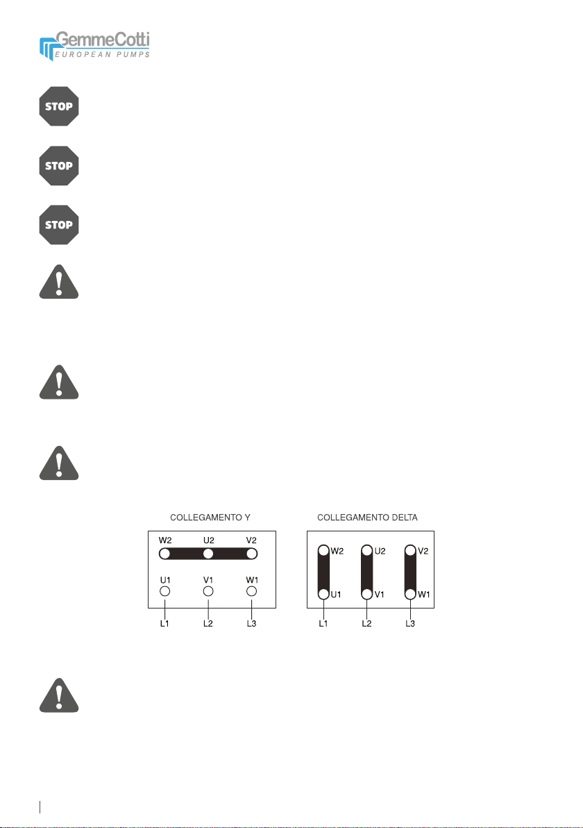
2.8 Motor Connection
Check that the tension and frequency printed on the label of the motor correspond to
those of the electric system to be used.
Don’t connect the electric motor directly to the main system but protect the dedicated
system with a suitable main switch with adequate safety protections against overloads.
The electric connections have to be always carried out by an expert qualied electrician.
The motors have to be supplied with three-phase tensions or if required by the customer,
with mono phase tension. The type of connection of the three-phase motors can be Star
(Y) or Delta (Δ) according with the power supply 380 or 220 VAC (see picture 1).
Make sure that the sense of rotation of the motor is that specied on the pump head and
eventually indicated by a sticker arrow on the motor fan; to change the sense of rotation
it’s sufcient to change two of the three entering line (E.g . L1 with L2) in three-phase
motors.
Picture 1
8
Dangerous or hazardous actions can cause serious injuries or death to people or serious
damage to materials and so it’s important to assure the respect of all the warnings
relative to the safety and the correct use written in this manual.
Verify always that the pumped liquid is compatible with the materials of construction of
the pump. For any clarication please contact Ekin Endüstriyel technical ofce.
In case of use for pumping aggressive, toxic liquids or liquids dangerous for the health
of the personnel, it’s necessary to install on the pump an adequate protection for the
containment, the collection and the warning of any dangerous product in case of
leakage: e.g. Danger of pollution, contamination, injuries and/or death.
Do not pump liquids containing solids in suspension. Mag drive pumps are designed
to pump clean liquids. The use of a suction strainer is strongly recommended (however
the lter has to be kept clean). We suggest a continuous check of the suction strainer
to avoid obstruction of the suction causing cavitation. Avoid in particular to pumping
liquids containing ferro oxides or other ferromagnetic particles, even if small.
Read the following instructions to change the sense of rotation:
• Wear individual homologated protection devices (e.g. gloves, glasses).
• Make sure that the operating conditions are analogous to the specications of the pump (see
paragraph 7).
• Install the pump in the hydraulic system.
• Open the suction and the discharge valve completely.
• Fill the pump with the liquid. It’s recommended to perform this test with an inert liquid like
water.
• Do not run the pump dry (Note: the design of mag drive pumps don’t allow dry running
because it causes damages to the inner components of the pump).
• Start the motor only for one or two seconds to check that the sense of rotation is in the
same direction of the arrow on the pump head or on the motor and on the technical
drawing of the pump (the sense of rotation is clockwise looking at the front of the pump and
counterclockwise looking at the motor fan).
A pump turning backwards will pump but at a greatly reduced capacity and pressure.
3. OPERATION
3.1 Use and Safety
9
Do not reduce the suction. Reduction of the suction is responsible of the cavitation of the
pump, which causes a loss of efciency and a rapid wear. Reduction of the discharge
are not advisable, if required, reduction of the capacity can be obtained by means of a
valve installed on the discharge pipe.
Do not loosen the connection of the pump while it’s under pressure.
Do not start and/or use the pump if there are signs of leak in the system.
The working temperatures have to respect the characteristics of the construction
materials of the pump:
0 - 60 °C polypropylene execution (PP)
0 - 80 °C PVDF execution
Do not allow the pump to run dry (Note: the mag drive pump design doesn’tallow the
dry-running functioning because it will damage irrevocably the inner parts of the pump).
An accidental failure can generate sprinklings up to considerable distances. In case of
vibrations or anomalous noises, stop the pump immediately.
Do not pump inamed liquids.
Do not touch the pump while operating.
Before touching the motor or the bracket switch off the electric current.
3.2 Dry-Running
Fill the pump with water or with the liquid to be pumped before starting the unit. This will
protect the bearings and the shaft of the pump against dry running. Do not allow the
pump to run dry because this can cause serious damages to the internal parts of the
pump due to the lack of the necessary lubrication.

10
3.3 Temperature
Increasing the temperature of the pumped liquid can damage the pump and/or the
piping/ttings and there can be a situation of serious danger for the people in the nearby.
Avoid sudden changes of the temperature and do not exceed the temperature specied
in your order. See the value of temperatures of the construction materials of the pumps
in the paragraph 3.1.
Some liquids react with water. Verify if the liquid to be pumped reacts with water. In this
case the system has to be completely emptied and dried.
When the pumping station is new, it’s necessary to ll the system with water to control
that there are no leaks. When the pump is installed over head it has to be primed, this
means that is has to be lled with the liquid and the suction piping has to be kept full of
liquid before starting the pump.
3.4 Before Starting
Make sure that the pump is installed in accordance with the instructions supplied in the previous
section 2.
3.5 Starting
Start the electric motor and gradually open the discharge pipe until you reach the required ow.
The pump can’t operate more than two or three minutes with the discharge closed. A longer
period can cause serious damage to the pump.
If the pressure shown on the pressure gauge on the discharge piping does not increase, stop the
pump immediately and release the pressure carefully.
Repeat the operation of installation of the pump as in paragraph 2.
If during the starting procedure there are changes of ow-rate, of density, temperature or viscosity
of the liquid, stop the pump and contact Ekin Endüstriyel technical service.
3.6 Optimum Conditions For Use
Operating continuously at the maximum performances (maximum capacity/head) there can be
an early wear of the pump. As a general rule, we recommend using the pump at half of its
maximum capacity (see the paragraph relative to the technical data) In any case do not allow the
pump to work out of curve.

11
The capacity and the head of the pump refer to water pumping at room temperature. If it
pumps high temperature liquids or other viscosities and densities, the performances
have to be proportionately decreased. Pumps of series HTM work well with liquids
having a viscosity up to 100 CPS3 and specic gravity up to 1.93. However both the
viscosity and the specic gravity have to be communicated at the moment of quotation.
The electric motor is selected for the viscosity and the specic gravity communicated.
In the case of higher values, the power of the motor could be insufcient.
In some cases the pump can be used to empty tanks, in these situations the liquid can
stop owing in the pump while this is still working. In these cases a pump operating
without liquids (that means dry-running) can be dangerously damaged if it’s not stopped
immediately. For such applications the use of automatic equipment or the constant
presence of a person who can shut down the pump is recommended.
• Earplugs.
• Protective homologated caps against noises for the personnel in the proximity.
• Soundproong canopy for the pump. In these cases make sure that the motor ventilation is
guaranteed.
3.7 Shut Down
Normally the pump should be shut down only after closing the discharge valve. If the suction
valve is closed before the other, cavitation of the pump can occur.
If the suction is ooded, close the valve after shutting down the pump.
3.9 Noise Level
If the pump is temporary removed from the system and kept in stock, it’s necessary to follow the
instructions of paragraph 2.3 “Storage”.
In some circumstances, for example when the pump works with high pressure and low capacity
the noise increases and can be disturbing for the personnel working in the proximity. In this case
it’s possible to intervene with:
3.8 Long Pump Inactivity
If the pump has to remain inactive for a long period, before stopping it, it’s recommended
to let water ow in the system for several minutes so that you avoid any risk of internal
deposits or sediments or precipitations of solid parts. Drain the liquid in the pump. An
eventual freezing of the liquid inside the pump can cause damage. Always verify if
the pumped liquid reacts with water. In this case contact Ekin Endüstriyel to nd an
alternative solution.
The values indicated are merely indicative and can vary in the series of pumps mod. HTM.

12
In case of ordinary maintenance (as indicated in paragraph 4.2) the customer is
responsible for the correct assembly and disassembly of the pump. The warranty is no
more valid if the pump is manipulated/sabotaged, the parts used for the maintenance are
not GemmeCotti original or in case of operations not in compliance with the instructions
indicated in this manual. During ordinary maintenance the customer should check the
absence of leakage (through hydrostatic tests, paying attention to respect the NP of
the pump.), the magnet/impeller alignment, the correct shaft positioning, the correct
bearing placement and the right functioning of the pump. For the tightening torque of
the screws please refer to paragraph 4.7. Pay attention also to avoid ruining the o-ring
when mounting it.
4. MAINTENANCE
4.1 General Dispositions
Clean the external surface of the pumps using only antistatic equipment. Every operation
executed on the apparatus has to be done after the disconnection of electric supply.
During the warranty period extraordinary maintenance is allowed only for GemmeCotti personnel
or personnel authorized by GemmeCotti. All the operations described in the paragraphs below
have to be done exclusively by qualied staff and following step by step all the warnings written
in this manual.
Use exclusively a goods lift to move pumps with weight higher than 16 kg. During the
movements of the machine or parts of the machine avoid collisions or falls which can
damage the apparatus.
Before disassembling the parts of the pump, make sure that the dangerous internal
liquids have been removed/washed. The pump has to be drained and decontaminated.
Pay attention that some internal liquids can have dangerous reactions in contact with
water.
During the operations of unloading of dangerous liquids make sure that situations of
danger for people or environment don’t occur.
4.2 Inspections
In general mag drive pumps do not need a “routine” maintenance and most of all they don’t
require frequent dismantling. However periodical inspections are advisable to verify the state of
wear of the impeller, the shaft, the o-rings and the bearings and if the general conditions of the
internal parts of the pump are good.
13
The time between the inspections is strongly dependent on the operation conditions of the pump:
the characteristics of the liquid, the temperature, the materials used and obviously the period of
operation.
After the rst start-up of the pump we strongly recommend an inspection of the bearings after 3
months of functioning. If the inspection has positive results, we recommend a second check after
further 6 months. The following inspection can be scheduled after another year of functioning
(about 2000 working hours of the pump). In any case it is advisable to replace the bearings in
PTFEC every 2000 hours of functioning of the pump. All the other components can be replaced
only when they show signs of wear.
If a problem occurred or the pump needs a complete inspection see section “Problem solutions”
and “Pump disassembly”.
4.3 Procedure Before Disassembly
If the pump has pumped hot liquids, make sure that it’s been cooled before the
disassembly procedure. It’s possible that the pump has pumped toxic and/or dangerous
liquids: so it’s necessary to wear protection for the skin and the eyes.
Make sure that the pump has been carefully decontaminated and cleaned. Wash
and neutralize completely the dangerous liquids inside the pump. The liquid has to
be collected and eliminated according to the existing environmental laws. After
disconnecting the discharge and suction pipes close the extremities.
GemmeCotti pumps contain extremely strong magnets. The use of non ferro-magnetic
tools and working surfaces is highly recommended. Pay attention to the strong magnetic
attraction when disassembling/assembling the unit motor-external magnet of the pump.
The area in which maintenance is done has to be clean and without ferric particles that
can be attracted by the magnets.
4.4 Disassembly
The photos used to show the operations of disassembly refer to a particular pump model of the
series HTM and consequently the pump supplied to you can be slightly different from what is
shown.
4.4.1 Main Parts
The drawing below shows a section with all the main parts of a pump series HTM in thermoplastic
material (In particular models 15 and 31).
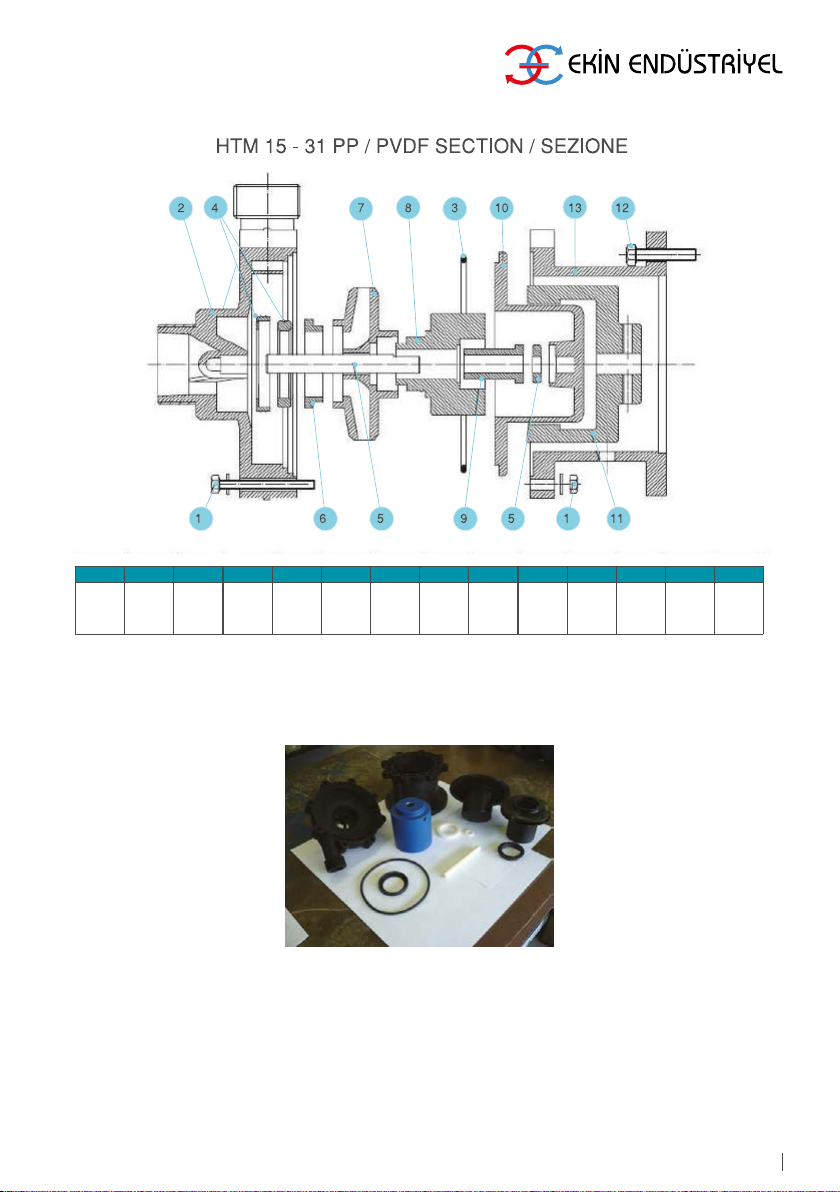
14
Photo N. 1 shows the main parts of a pump series HTM in thermoplastic material
(excluding the motor)
Photo 1
POS. 1 2 3 4 5 6 7 8 9 10 11 12 13
Part
Descr.
Set
Screws
Front
Casing O-ring Casing
Thrust
Bush
Shaft +
Ring
Impeller
Thrust
Bearing
Impeller Int
Magnet Bearing Rear
Casing
Ext.
Magnet Screws Bracket

15
4.4.2 Disassembling The Pump From The Motor
1. Remove the screws securing the pump and the motor ange (Photo N. 2)
2. Separate the pump from the motor (Photo N. 3)
3. If it’s necessary to remove the external magnet (Photo N. 4 in blue) from the motor shaft proceed
unscrewing the grub screw with an Allen key and then use a puller to avoid damage to the
motor shaft or the external magnet.
4. From the bracket of the pump disassemble the head (Photo No. 5 and 6) after removing the
bolts.
Photo 2
Photo 5 Photo 6
Photo 3 Photo 4
This manual suits for next models
14
Table of contents
Popular Water Pump manuals by other brands

Speck
Speck NP25/15-500 operating instructions

Crivit
Crivit 87116 instruction manual

Central Machinery
Central Machinery CENTRAL MACHINERY 92274 Assembly and operating instructions

salmson
salmson Sanitson Premium Series Installation and starting instructions

Pfeiffer Vacuum
Pfeiffer Vacuum DUO 3 operating instructions

Orion
Orion 22206 manual

BUSCH
BUSCH Mink MV 0502-0602 B instruction manual

Lutz-Jesco
Lutz-Jesco MEMDOS SMART LDX operating instructions

Shenchen Precision Pump
Shenchen Precision Pump YZ Series instruction manual

Ingersoll-Rand
Ingersoll-Rand 650484-X Operator's manual

Simer
Simer 3995 owner's manual

Himel
Himel HAV SP Series user manual


