Orion 22206 User manual

1
USER MANUAL / BRUKSANVISNING
Part No. / Art. Nr.:
22206 – 22208 – 22210 – 22211 – 22216 – 22238 – 22221 – 22226
22310 – 22320 – 22325 – 22328
AIR OPERATED
DIAPHRAGM PUMP
TRYCKLUFTSDRIVNA
MEMBRANPUMPAR
105132C

2
TECHNICAL DATA / TEKNISKA DATA
TECHNICAL DATA 22310 22320 22325 22328 22210 22221 22227 22211 22230 22238 22206 22208
Ratio 1:1
Maximum free ow 100 l/min 50 l/min 38 l/min
Delivery per stroke 0,25 l 0,1 l 0,07 l
Air pressure MPa (bar) 0,15 - 0,8 (1,5 - 8)
Solid in suspension max
size
4 mm 3 mm
Maximum suction head 4 m (dry)
8 m (wet)
6 m (dry)
8 m (wet)
4,5 m (dry)
7 m (wet)
Weight 7,2 kg metallic series with Aluminium
body
11,2 kg metallic series with
Stainless steel body
5,1 kg non metallic series
3,5 kg metallic series with aluminium body
2,2 kg non metallic series
1,9 kg
Fluid inlet (single inlet) 1" BSP/NPT (F) and ange 1/2" NPSM (F) and ange with metallic body
(BSP- NPT (F) and ange with plastic body)
1/2" BSP - NPT
(F)
Fluid inlet (double inlet) – 2 x 3/8" NPSM (F) with metallic body
(BSP - NPT (F) with plastic body)
2 x 3/8" BSP -
NPT (F)
Fluid outlet 1" BSP/NPT (F) and ange 1/2" NPSM (F) and ange with metallic body
(BSP - NPT (F) plastic body)
1/2" BSP - NPT
(F)
Air inlet 3/8" NPSM (F)
Noise level 80 dB
Temperature range 0 - 70 ºC
EN
TEKNISKA DATA 22310 22320 22325 22328 22210 22221 22227 22211 22230 22238 22206 22208
Tryckförhållande 1:1
Max. öde fritt utlopp 100 l/min 50 l/min 38 l/min
Volym per slag 0,25 l 0,1 l 0,07 l
Tryckluft 0,15 - 0,8 (1,5 - 8)
Max partikelstorlek 4 mm 3 mm
Max sughöjd 4 m (torrt)
8 m (vått)
6 m (torrt)
8 m (vått)
4,5 m (torrt)
7 m (vått)
Vikt 7,2 kg (aluminium)
11,2 kg (rostfritt)
5,1 kg (plast)
3,5 kg (aluminium)
2,2 kg non metallic series
1,9 kg
Inlopp singel 1" BSP/NPT (F) med äns 1/2" NPSM (F) med äns (aluminium)
(BSP- NPT (F) med äns (plast))
1/2" BSP - NPT
(F)
Inlopp dubbel – 2 x 3/8" NPSM (F) (aluminium)
(BSP - NPT (F) (plast))
2 x 3/8" BSP -
NPT (F)
Utlopp 1" BSP/NPT (F) med äns 1/2" NPSM (F) med äns (aluminium)
(BSP - NPT (F) (plast))
1/2" BSP - NPT
(F)
Inlopp luft 3/8" NPSM (F)
Ljudnivå 80 dB
Arbetstemperatur 0 - 70 ºC
SV

3
GENERAL / ALLMÄNT / GÉNÉRALITÉSINSTALLATION / INSTALLATION
Always read the manual carefully and make sure You understand it before
any action is carried out. The pump must not be used for any other purposes
than recommended. Liquids not suitable for the pump can cause damage to
the pump and imply serious personal damage. Always consult your Alentec
& Orion distributor if you have any doubt regarding of the compatibility of
uids with the pump materials.
WARNING! Possible explosion hazard can be the result if 1,1,1-
Trichloroethylene, Methylene Chloride or other Halogenated hydrocarbon
solvents are used in pressurized uid systems having Aluminum wetted
parts. This can cause death, serious bodily injury and /or property damage.
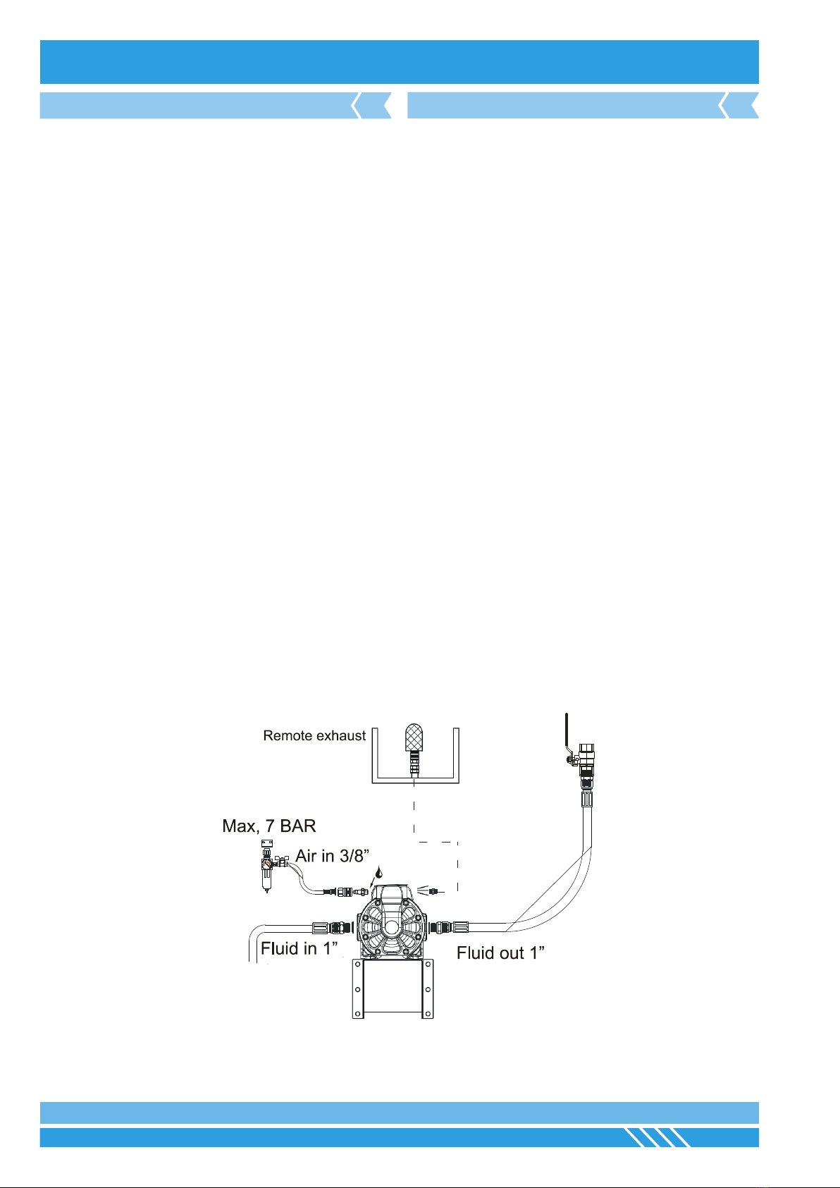
The pump must always be installed and used in accordance with the
existing local and national sanitary and safety regulations and laws. The
pump can create uid pressure equal to the air supply pressure. Do not
exceed the maximum permissible air supply pressure of 7 bars (100 psi).
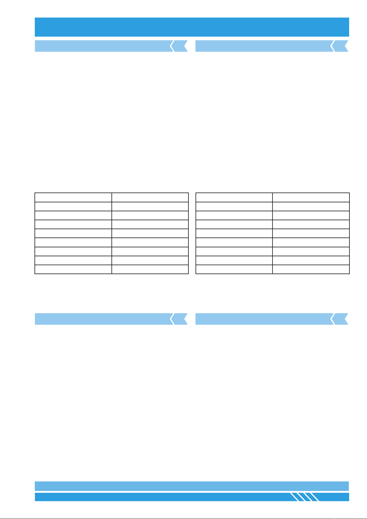
Material Temperatue range
PTFE 5°C-105°C
NBR 10°C-80°C
Acetal 10°C-90°C
Hytrel® 10°C-90°C
Polypropylene 10°C-80°C
Viton® -10°C-120°C
Santoprene® -18°C-93°C
Neoprene -29°C-135°C
Air powered double diaphragm pumps are reciprocating positive
displacement pump with two pumping chambers. Two diaphragms, centrally
located in the chambers, separate the compressed air (dry side) from the
liquid being pumped (wet side). A shaft connects the two diaphragms to
each other.
A valve (air motor) distributes the air from one chamber to the other
alternately, thus a reciprocating movement of the diaphragms is created.
With each stroke, liquid is discharged by one of the diaphragms while the
opposite diaphragm sucks new uid into the expanding chamber.
Four check valves, two on the pressure side and two on the vacuum side,
control and direct the ow of liquid.
Läs alltid manualen noggrant och se till att du förstått den innan någon
åtgärd startas. Pumpen får aldrig användas för andra ändamål än vad
som rekommenderas i denna manual. Vätska som inte passar kan skada
pumpen och orsaka svåra skador på personer. Om tveksamhet råder om
vätskan är tillåten i pumpen, kontakta alltid Alentec & Orion AB eller dess
auktoriserade distributör.
VARNING! Farliga explosioner kan uppstå om 1,1,1- Trikloretylen,
Metylklorid eller andra kolväten används i trycksatta system där de kan
komma i kontakt med aluminium. Svåra personskador kan uppkomma.
Pumpen skall alltid installeras och användas på ett säkert sätt med hänsyn
till användande av lokala och nationella lagar och säkerhetsbestämmelser.
Pumpen kan skapa ett vätsketryck som är lika stort som den anslutna
tryckluften. Överskrid aldrig det maximalt tillåtna lufttrycket på 7 bar (100
psi).
Max. arbetstemperatur för de olika packningsmaterialen:
Material Temperaturområde
PTFE 5°C-105°C
NBR 10°C-80°C
Acetal 10°C-90°C
Hytrel® 10°C-90°C
Polypropylene 10°C-80°C
Viton® -10°C-120°C
Santoprene® -18°C-93°C
Neopren -29°C-135°C
Membranpumpen är en tryckluftdriven pump med två kammare för vätskan
och med positivt deplacement. Två membran, centralt placerade i kamrarna,
skiljer tryckluften från vätskan som skall distribueras. En slipad axel med
tätningar, för att förhindra läckage, håller ihop de två membranen.
En ventil i luftmotorn ser till att tryckluften hamnar på rätt sida av
membranen. Så länge det nns tryckluft anslutet kommer pumpens
membran att röra sig fram och åter för att vid varje slag trycka ut vätskan
i rörledningen samt suga in ny vätska på den andra sidan av pumpen. Allt
detta styrs av 4 backventilkulor (2 på trycksidan och 2 på sugsidan) vilka
ser till att den trycksatta vätskan hamnar i rörledningen och den uppsugna
vätskan på sugsidan.
SAFETY PRECAUTIONS SÄKERHETSFÖRESKRIFTER
EN SE
DESCRIPTION BESKRIVNING
EN SE

INSTALLATION / INSTALLATION / INSTALLATION / INSTALLATION / INSTALACIÓN
4
INSTALLATION / INSTALLATION
CAPACITY CURVES KAPACITETSKURVOR
EN SE
1" Pumps (100 l/min)
1/2" Pumps (50 l/min)
1/2" Pumps (38 l/min)

5
GENERAL / ALLMÄNT / GÉNÉRALITÉSINSTALLATION / INSTALLATION
DIMENSIONS DIMENSIONER
EN SE
1" Pumps (100 l/min)
A B C D E F G H I J K L
8,5” 7,44” 8,94” 6,89” 6,06” 0,35” 7,24” 8,27” 3,72” 1" BSP 8,27" 3/8" BSP
216 mm 189 mm 270 mm 175 mm 154 mm 9 mm 184 mm 210 mm 94,5 mm 210 mm
1/2" Pumps (50 l/min)
A B C D E F G H I J K L
6.14” 6.3” 6.57” 4.13” 4.8” 0.31” 5.75” 5.51” 2.76” 1/2" BSP 5,91" 3/8" BSP
156 mm 160 mm 167 mm 105 mm 122 mm 8 mm 146 mm 140 mm 70 mm 150 mm
1/2" Pumps (38 l/min)
A B C D E F G H I J K L
3/2" BSP 3/8" BSP
130 mm 160 mm 162 mm 105 mm 122 mm 8 mm 140 mm 135 mm 70 mm 145 mm

INSTALLATION / INSTALLATION / INSTALLATION / INSTALLATION / INSTALACIÓN
6
INSTALLATION / INSTALLATION
The pipe work must be installed according to local regulations for this type
of equipment.
Never mount a pump directly onto a sheet metal wall or similar construction,
which can create noise resonance and augment the normal noise level of
the pump.
If the pump is used for liquids that are hazardous for people or the
environment, it must be installed in a container to prevent and containany
leakage.
A hose must be mounted between the outlet of the pump and the xed pipe
work.
At each branch and before each hose reel/ outlet a shut-off valve should be
installed. It is also advisable to t a lter to prevent any dirt from entering,
prior the meters and valves.
When starting up the system for the rst time, all valves and meters should
be opened to bleed air from the system.
Do not let the pump run fast when starting up a new system or changing
barrels in an existing system. Start the pump by lowering the air pressure
on initial priming and increase the air pressure gradually as the system is
primed.
In case of diaphragm pump failure, the air exhaust will expel the liquid being
pumped.
Rörledningssystemet ska utföras med iakttagande av de
rörledningsbestämmelser och normer som myndigheterna har beslutat ska
gälla för denna typ av utrustning.
Kontrollera om ”din” vätska omfattas av några speciella regler.
Montera aldrig en pump direkt på en plåtvägg, eller annan liknande
konstruktion som kan ge resonansljud och förstärka pumpens normala
ljudnivå.
Om pumpen används för vätskor som är skadliga för människor eller miljön
måste den installeras i en behållare för uppsamling av eventuellt spill.
En slangledning skall monteras mellan pumpens utloppsanslutning och
rörledningen.
I början av varje rörledning och vid varje förgrening och före varje slangrulle/
uttagsställe ska en avstängningsventil monteras. Det rekommenderas även
att montera ett lter.
Vid första starten ska alla mätverk och avstängningsventiler öppnas för
att låta den annars innestängda luften komma ut. Ibland kan det vara
nödvändigt att lossa på någon högt belägen koppling eller skarv för att få
bort luftckor.
Låt inte pumpen "rusa" under uppstart eller vid byte av fat när rörledningen
återfylls.
Sänk farten på pumpen genom att sänka lufttrycket.
Om pumpens membran är skadade kan den vätska som pumpas tryckas ut
genom luftutsläppet.
INSTALLATION INSTALLATION
EN SE

7
GENERAL / ALLMÄNT / GÉNÉRALITÉS
2
1
3
REPAIR AND MAINTAINANCE / SERVICE OCH UNDERHÅLL
Before any service is done to the pump, disconnect air supply!
1. Close uid valves
2. Drain the uid inside the pump.
3. Remove the directional valve, be careful not to damage the seals.
4. Remove the diaphragm cap screws, NOTE: to tighten these screws
you must use a torque wrench calibrated to(see table on page 9)
5. Remove the cover by gently pulling back.
6. Remove the used diaphragm and place the new one in the correct
position.
Reassemble components.
Looking at the uid inlet, remove the side cover as shown in the gure,
following the procedure ”diaphragm replacement”.
Once the shaft is visible, use the following procedure:
1. Remove the shaft from its housing by pulling it from one end. The
Teon® sleeve is threaded into the body. To remove, use snap ring
pliers in the two holes as indicated in the gure.
2. Once the cap has been removed, remove the quad ring inside the
pump body
3. Replace the kit following the correct order in the assembly drawing.
Reassemble the pump in reverse order.
Innan något arbete utförs på pumpen måste lufttillförseln kopplas bort!
1. Stäng vätskeventilerna.
2. Tappa ur vätskan från pumpen.
3. Ta bort riktningsventilen, se till att inte packningarna skadas.
4. Ta bort skruvarna som håller membrankåporna. (OBS, när dessa
återmonteras måste en momentnyckel användas med värde enligt
tabell på sid. 9)
5. Drag försiktigt loss kåporna.
6. Ta bort de gamla membranen och montera de nya i rätt position.
Återmontera i omvänd ordning
Med vätskeinloppet emot dig, ta loss den högra pumpsidan enligt
instruktioner i ” Byte av membran”.
När axeln är synlig gör enligt följande:
1. Ta loss axeln genom att dra i dess ände. Teon® hylsan är gängad
i kroppen och tass lättast bort med hjälp av en låsringstång enligt
guren.
2. När hylsan är borta, ta loss quad-ringen i pumpkroppen.
3. Montera de nya delarna enligt guren nedan.
Montera ihop pumpen.
4
A
6
5
3
DIAPHRAGM REPLACEMENT BYTE AV MEMBRAN
EN SE
PUSHING ROD MEMBRANAXEL
EN SE

INSTALLATION / INSTALLATION / INSTALLATION / INSTALLATION / INSTALACIÓN
8
REPAIR AND MAINTAINANCE / SERVICE OCH UNDERHÅLL
1. Close uid valves.
2. Drain the uid from inside the pump.
3. Remove the directional valve; take care not to damage the seals.
4. Remove the valve cover by loosening the allen screws, note the
orientation of the cap as it is critical that it is remounted correctly.
5. Install new set of valves according to these assembly drawings. Make
sure that the ball guides are assembled as shown in the gure to the
left, and tighten the screws with maximum torgue(see table page 9).
6. Assemble the directional valve taking care not to damage the o-rings
and tighten the screws with a maximum torque of 44.25 lbf in (5Nm).
1. Stäng inlopps- och utloppsventiler.
2. Låt vätskan i pumpen rinna ur.
3. Ta bort riktningsventilen, se till att inte packningarna skadas.
4. Ta loss kåporna över backventilerna genom att lossa insex skruvarna.
Notera hur den är monterad då det är väldigt viktigt att den återmonteras
i samma riktning.
5. Montera de nya backventilerna enligt gur nedan. Se till ventil guiderna
monteras enligt den vänstra guren. Skruvarna ska dras med moment
enligt tabell på sid 9.
6. Återmontera riktningsventilen, se till att o-ringarna inte skadas. Dra
skruvarna med momentnyckel inställd på 5 Nm.
BALL VALVES REPLACEMENT BYTE AV BACKVENTILER
EN SE

9
GENERAL / ALLMÄNT / GÉNÉRALITÉSREPAIR AND MAINTAINANCE / SERVICE OCH UNDERHÅLL
AIR SENSORS RIKTNINGSSENSORER
EN SE
The air sensors are on the inside part of the diaphragm covers. To access
them, follow the procedure for “replacing diaphragms”.
Once the covers are removed follow this procedure:
1. Remove the two screws holding the air sensor.
2. Remove all components of the sensor, clean the area.
3. Install the new components in the order shown.
4. Fit the cover and tighten the screws with a torque according to the
table on page 9. Remount the remaining components in reverse order.
Riktningssensorerna är placerade på insidan av membrankåporna. För att
komma åt dem följ anvisningarna i kapitel ”Byte av membran”.
När kåporna är loss följ instruktionerna nedan:
1. Ta loss de två skruvar som håller sensorerna på plats.
2. Ta loss alla delar av sensorn och rengör området de satt i.
3. Montera de nya delarna i den ordning som visas nedan.
4. Sätt tillbaka kåporna, använd momentnyckel inställd enligt tabell på
sida 9. Montera återstående delar av pumpen.
PUMP DIAPHRAGM COVER DIRECTIONAL VALVE VALVE CAP
1/2” (38 l/min) 70,91 lbf in (8Nm) 44.25 lbf in (5Nm) 30.9 lbf in(2Nm) composite
1/2” (50 l/min) 48.7-53.1 lbf in (5,5-6Nm) 44.25 lbf in (5Nm) 35.5 lbf in (4Nm) aluminium
30.9 lbf in(2Nm) composite
1” (100 l/min) 137.7 lbf in (15Nm) 44.25 lbf in (5Nm) 35.5 lbf in (4Nm) aluminium
30.9 lbf in(2Nm) composite

10
TROUBLESHOOTING / FELSÖKNING
SYMPTOM POSSIBLE FAULT SOLUTION
The pump does not
work
The discharge valve is not open Open the valve on the discharge side.
No air supply Turn on the compressor and open valves and regulator.
The air supply pressure is too low. Check the compressor and other components.
The air pipes or ancillary equipment is clogged . Check and clean the air line.
The exhaust port(mufer) is clogged. Check and clean the exhaust port and mufer.
The uid pipe is clogged. Check and clean the uid line.
Pump is clogged. Remove, inspect and clean the pump.
The pump runs but no
uid is delivered
The valve on the suctions side is not open. Open the valve on the suction side
Too much suction or discharge height. Conrm the conguration of the pipe and reduce the height
differences.
Fluid pipe on the discharge side(incl. lter) is clogged. Check and clean the uid line.
Pump is clogged. Dismantle the pump, check and clean.
The ball and ball set is worn or damaged. Inspect and replace parts.
The ow is decreasing
The air supply pressure is low. Check the compressor and conguration of the air line.
The air line or components are clogged. Check and clean the air line.
Valve on the discharge side will not open normally. Adjust the discharge valve
The uid is mixed with air Check the suction side so no air can enter.
Cavitation occurs. Adjust air supply pressure and discharge pressure and
reduce suction height.
Vibrations.
Adjust air supply pressure and discharge pressure. Reduce
the ow through the inlet valve to adjust pressure and ow
of the uid.
Ice formation in the air exhaust.
Remove ice from the air bypass valve and check and clean
air lter. Use a pipe in the exhaust air so the ice does not
form in the mufer.
The uid line (incl. lter) clogged. Check and clean the uid pipe and strainer.
The exhaust port (mufer) clogged. Check and clean the exhaust port and mufer.
Pump clogged. Remove , inspect and clean the pump body.
Leakage of uid
through the exhaust The diaphragm is damaged Remove and inspect the pump and replace the diaphragm.
Irregular noise
The air supply pressure is too high. Adjust the air supply pressure.
The pump is clogged with particle larger than the
diameter allowed. Remove check and clean the pump body.
Irregular vibration
The connections or the support of the pump are loose Check all connections and tighten where needed.
The air supply pressure is too high. Adjust the air supply.
Air bubbles in the uid Diaphragm damaged Replace diaphragm.
Suction hose loose or damaged. Check the suction side and tighten/replace.
Air leakage Worn directional valve Replace directional valve components.
Pump won´t start and
air leakage while no
cycles
Damaged air sensors. Replace air sensors.
Worn directional valve Replace directional valve components
EN

11
TROUBLESHOOTING / FELSÖKNING
SYMPTOM MÖJLIG ORSAK ÅTGÄRD
Pumpen gör inga slag
Utloppsventilen är stängd. Öppna utloppsventilen.
Ingen tryckluft. Starta kompressor, öppna ventiler och regulator.
För lågt lufttryck Kontrollera kompressor och övriga komponenter.
Igensatta luftledningar/komponenter. Kontrollera och gör ren luftledningen.
Luftutloppet är igensatt. Kontrollera och gör rent.
Vätske rör/slang är igensatta. Kontrollera och gör rent.
Pumpen är igensatt Ta loss. Inspektera och gör rent.
Pumpen går men
levererar inte
Ventil på onloppsisdan är stängd. Öppna ventilen.
För stora höjdskillnader på inlopps/utloppssida. Kontrollera systemkongurationen.
Utloppsrör/slang (inkl. Filter) är igensatta. Kontrollera och gör rent.
Pumpen är igensatt Ta loss. Inspektera och gör rent.
Backventilskomponenter är skadade. Kontrollera och byt backventilsdelar.
Minskat öde
För lågt lufttryck. Kontrollera kompressor och luftkomponeneter.
Igensatt luftledning. Kontrollera och gör rent.
Utloppsventilen öppnar inte tillräckligt. Kontrollera utloppsventilen.
Luft är inblandad I vätskan. Kontrollera sugledningen så ingen luft kan komma in.
Pumpen kaviterar. Justera lufttrycket och sugledningen.
Pumpen vibrerar. Justera lufttrycket och sugledningen/ventiler.
Isbildning I luftutloppet. Ta bort isen och gör rent, anslut ett rör för att hindra is från
att bildas i ljuddämparen.
Vätskerör/slang (inkl. lter)är igensatta. Kontrollera och gör rent.
Luftutloppet(ljuddämpare) är igensatt. Kontrollera och gör rent.
Pumpen är igensatt. Ta loss, kontrollera och gör rent pumpen.
Vätskeläckage genom
luftutlopp Skadade membran Ta loss pumpen, inspektera membranen och byt.
Onormalt ljud För högt lufttryck. Justera lufttrycket.
Pumpen är igensatt av för stora partiklar från vätskan. Ta loss, inspektera och gör ren pumpen.
Onormala vibrationer Anslutningar eller fäste för pump sitter löst. Kontrollera och spänn åt där det krävs.
För högt lufttryck Justera lufttrycket.
Luftbubblor I vätskan. Skadade membran Ta loss pumpen, inspektera membranen och byt.
Sugledning lös eller skadad.. Kontrollera och dra åt/byt.
Luftläckage Skadad eller sliten riktningsventil Byt riktningsventil
Luftläckage och pum-
pen går inte
Skadade riktningssensorer Byt riktningssensorer..
Skadad eller sliten riktningsventil Byt riktningsventil
SE

12
EXPLODED VIEW 3/8" -1/2" COMPOSITE PUMPS / SPRÄNGSKISS 3/8" -1/2" KOMPOSITPUMPAR

13
EXPLODED VIEW 1/2" METALLIC PUMPS / EXPLODED VIEW 1/2" METALLIC PUMPS

14
EXPLODED VIEW 1" PUMPS / SPRÄNGSKISS 1" PUMPAR

15
REPAIR KITS FOR 3/8" & 1/2" PUMPS / REPARATIONSSATSER FÖR 3/8" & 1/2" PUMPAR
ART.NO DESCRIPTION FOR PUMP MOD CONSISTS OF: EXTRA
2420300 Directional valve All 1/2" pumps 1 (1:1-1:12)
2420332 Directional valve (PP) All 3/8” pumps 1 (1:1-1:12)
2420321 Balls 22210, 22211, 22216,
22218, 22221, 22226
2 ACETAL
2420319 Balls 22206, 22208, 22215 2 PTFE
2420315 Ball guide and seat 22210, 22211, 22216,
22218, 22221, 22226
3 (3:1-3:3) Seats/seals/guides/SS/viton/Acetal
2420316 Ball guide and seat 22206, 22208, 22215 3 (3:1-3:3) Seats/seals/guides/SS/viton/Acetal
2420333 Shaft and bushing 22206 4 (4:1-4:4) Bushing/seals/shaft/PTFE/FKM/SS
2420334 Shaft and bushing 22208 4 (4:1-4:4) Bushing/seals/shaft/Conductive PTFE/
FKM/SS
2420304 Shaft and bushing 22210 4 (4:1-4:4) Bushing/seals/shaft/PTFE/NBR/SS
2420307 Shaft and bushing 22211, 22215, 22216,
22221, 22226
4 (4:1-4:4) Bushing/seals/shaft/PTFE/Viton/SS
2420307 Shaft and bushing 22218 4 (4:1-4:4) Bushing/seals/shaft/conductive acetal/
Viton/SS
2420335 Diaphragms+ shaft All 3/8” pumps 5:1-5:2, 4:4 Santoprene®
2420336 Diaphragms+ shaft All 3/8” pumps 5:1-5:2, 4:4 PTFE
2420303 Diaphragms+ shaft All 1/2" pumps 5:1-5:2, 4:4 HYTREL
2420309 Diaphragms+ shaft All 1/2" pumps 5:1-5:2, 4:4 PTFE for 1/2"
2420301 Air sensor All 3/8” & 1/2" pumps 6 (6:1-6:7)

INSTALLATION / INSTALLATION / INSTALLATION / INSTALLATION / INSTALACIÓN
16
REPAIR KITS FOR 1" PUMPS / REPARATIONSSATSER FÖR 1" PUMPAR
ART.NO DESCRIPTION FOR PUMP MOD CONSISTS OF: EXTRA
2420350 Directional valve DF100 (aluminium) 1 (1:1-1:12)
2420351 Directional valve DF100 (polypropylene) 1 (1:1-1:12)
2420365 Balls 22310 2 Acetal
2420363 Balls 22328,22325 2 PTFE
2420364 Balls 22320 2 NBR
2420360 Ball guide and seat 22325, 22328 3 (3:1-3:3) Seats/seals/guides/SS/viton/Polypro-
pylen
2420357 Ball guide and seat 22310 3 (3:1-3:3) Seats/seals/guides/SS/NBR/Acetal
2420357 Ball guide and seat 22320 3 (3:1-3:3) Seats/seals/guides/SS/NBR/Acetal
2420352 Shaft and bushing 22310 4 (4:1-4:4) Bushing/seals/shaft/PTFE/NBR/SS
2420353 Shaft and bushing 22325 4 (4:1-4:4) Bushing/seals/shaft/PTFE/Viton/SS
2420380 Shaft and bushing 22328 4 (4:1-4:4) Bushing/seals/shaft/conductive acetal/
Viton/SS
2420398 Shaft and bushing 22320 4 (4:1-4:4) Bushing/seals/shaft/PTFE/NBR/SS
2420368 Diaphragms+ shaft 22310,22325 5:1-5:2, 4:4 HYTREL
2420371 Diaphragms+ shaft 22328 5:1-5:2, 4:4 PTFE
2420457 Diaphragms+ shaft 22320 5:1-5:2, 4:4 NBR
2420301 Air sensor All pumps 6 (6:1-6:7)

17
GENERAL / ALLMÄNT / GÉNÉRALITÉS
EC CONFORMITY DECLARATION / KONFORMITETSDEKLARATION
Alentec&Orion AB, Grustagsvägen 4, SE-13840, Älta, Sweden, declares by the present certicate that the mentioned machinery is
in conformity with the EC Directive (2006/42/EEC).
Alentec&Orion AB, Grustagsvägen 4, SE-13840, Älta, Sverige, deklarerar genom detta certikat att de omnämnda utrustningarna
är i överensstämmelse med EC Direktiv (2006/42/EEC).
EN
SE
105076
Krister Tynhage
Managing Director
Olle Berglund
Product Manager
Other manuals for 22206
1
This manual suits for next models
11
Table of contents
Other Orion Water Pump manuals

Orion
Orion KRF110-V-04E User manual

Orion
Orion 12750 User manual

Orion
Orion 220VAC User manual

Orion
Orion 11116 User manual

Orion
Orion KRF08A-B-04E User manual

Orion
Orion DP200 Series Operating manual

Orion
Orion 21650 User manual

Orion
Orion 22772 User manual

Orion
Orion 12540 User manual

Orion
Orion 12626 User manual