LUBE EGH-2C User manual

L-0195
Manually Operated Lubrication Pump
(Models: EGH-C and EGH-P)
Operation Manual
LUBE CORPORATION

Contents
Overview
Page
1. Models of Grease Feed Equipment 1
2. Specifications
2.1 List of Product Specifications
2.2 List of Product Code Numbers for EGH-C and EGH-P
2.3 Name of Each Section
3. Handling for Safety5
3.1 Installation
3.2 Port Connection
3.3 Greases to be Used and Replenishment
3.4 Usage Conditions
3.5 Air Bleeding
3.6 How to Operate the Handle (Operation and P.D.I.)
3.7 How to Replace the Cartridge
4. Pump Operation7
5. Failures and Countermeasures8
6. Causes of Grease Contamination and
Countermeasures
9
6.1 Causes of Contamination
6.2 Countermeasures
- 1 -
Overview
This grease feed equipment is a pump for force-feeding a comparatively small amount of grease manually to each
grease feed point from the distributor (constant-volume pressure-forwarding valve).
1. Models of Grease Feed Equipment
1.1 Name: Manually operated lubrication pump
1.2 Models: EGH-C and EGH-P
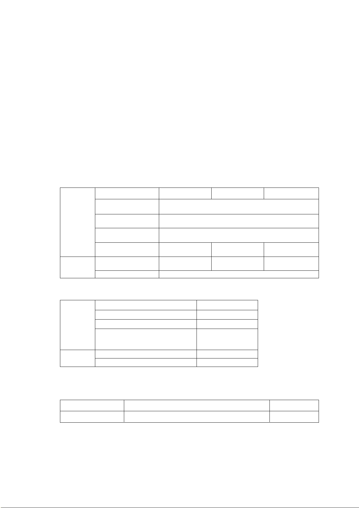
2. Specifications
2.1 List of Product Specifications
(1) EGH-C and E-GH-P type pumps
Model EGH-2C EGH-4C EGH-4CB
Discharging volume
(m
/stroke) 1
Discharging pressure
(MPa) 10
Pressure reducing
method Operation by the handle
Pump
Tank Cartridge type Cartridge type Cartridge type with
spring
NLGI viscosity
number 0 …* 0…* 0,1
Specified
grease Soap group Lithium family
* NLGI No. 1 may be used only under air temperature of 20°C or more.
Model EGH-3P
Discharging volume (m
/stroke) 1
Discharging pressure (MPa) 10
Pump
Tank Effective capacity
0.26 L
Plastic tank
NLGI viscosity number 000, 00, 0, 1
Specified
grease Soap group Lithium family
* NLGI No. 1 may be used only under air temperature 20°C or more.
(3) Pressure gauge (optional part)
Code No. Pressure range Connection port
109141 25 MPa R1/8

- 2 -
(4) Tank
Code No. Capacity (effective) Material
530377
539131
539133
0.26 L
0.4 L cartridge type
0.4 L cartridge type (with spring)
0.2 L cartridge type
PCTA
Polypropylene
Polypropylene
Polypropylene
(5) Waterproof cap for cartridge (optional part)
Code No. Use Material
530492 Cartridge (with spring) for outdoor use Polypropylene
2.2 List of Code Numbers for EGH-C and EGH-P
Code No. Model Type of Tank Pressure
reduction
103780
103781
103782
103783
EGH-2C
EGH-4CB
EGH-4C
EGH-3P
Cartridge
Cartridge (with spring)
Cartridge
0.26 L
Operation by
the handle
Ditto
Ditto
Ditto
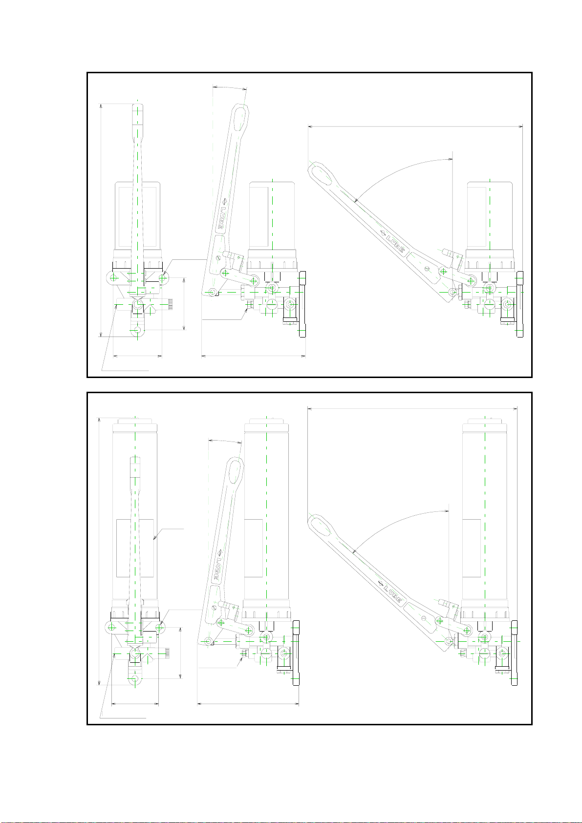
2.3 Name of Each Section
- 3 -
EGH-2C
70
75
3−φ9(穴)
(47.5゜)
(150)
(9.5゜)
エア−抜きバルブ
(310)
吐出口(Rc1/8)
(336)
Hole
Air bleed valve
Discharge port (Rc 1/8)
394
70
75
3−φ9(穴)
(47.5゜)
(150)
(9.5゜)
エア−抜きバルブ
(310)
吐出口(Rc1/8)
注意銘板
Caution plate
Air bleed valve
Discharge port (Rc 1/8)
Hole
EGH-4C
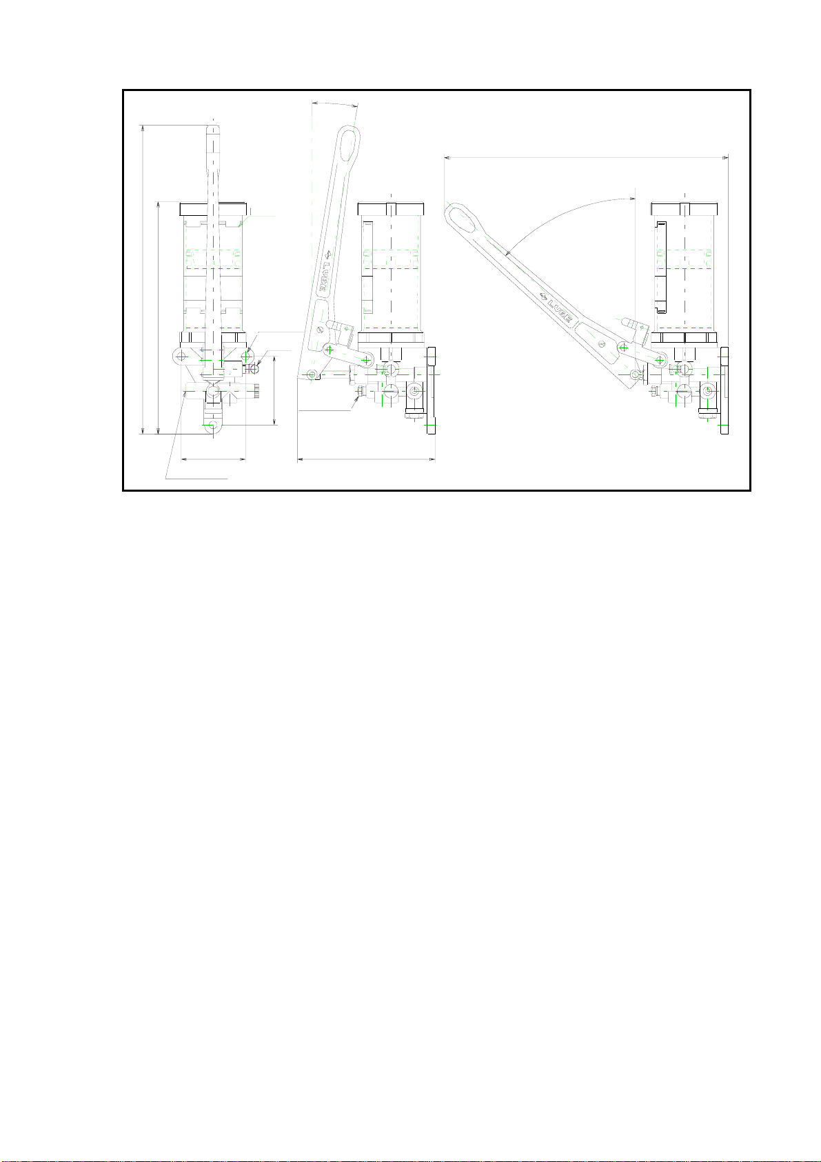
70
75
3−φ9(穴)
(47.5゜)
(150)
(9.5゜)
エア−抜きバルブ
(310)
吐出口(Rc1/8)
336
補給口
253
注意銘板
Caution plate
Replenishing
port
Air bleed valve
Discharge port (Rc 1/8)
Hole
EGH-3P
- 4 -

- 5 -
3. Handling for Safety
3.1 Product Installation
Choose a place for installation that allows easy operation of the handle, etc.
Mount the grease feed equipment on a vertical wall or a flat stand or board and secure it reliably.
Use M8 screws for installation and fix at three points.
If any vibration is expected, do not install the equipment directly but only through a rubber isolator, etc.
3.2 Port Connection
Carry out port connection by tightening with an appropriate torque and make sure that there is no grease leakage.
3.3 Greases to be Used and Replenishment
(1) Grease
Do not use any grease other than those lithium family greases specified in “2.1 List of Product
Specifications” so that no pump failure, clogging of the system, etc. occur.
(2) Replenishment
Standard 0.26 L tank
If the follow plate inside the tank has come down to the low level, replenish grease without fail.
In replenishing, feed grease only from the replenishing port. Otherwise, it may cause a failure. Use
appropriate attention so as not to introduce air, foreign substances, etc.
Cartridge type
If the end of the cartridge container has come down to the low level, replace the cartridge without fail.
Never reuse the cartridge, for example, by refilling it. Otherwise, the cartridge container may burst. Carry
out replacement operation with appropriate attention so as not to allow air, foreign substances, etc. to enter
referring to “3.7 How to Replace the Cartridge.”
3.4 Usage Conditions (When using the equipment, maintain the following conditions.)
Operating ambient temperature 0°C to +40°C
Operating ambient humidity 35% to 85%
3.5 Air Bleeding
After system piping work and when air is introduced into the pump, carry out air bleeding by all means. In
carrying out air bleeding, loosen the air bleeding valve of the pump (return for approximately a turn
counterclockwise) and move the handle to and fro until grease comes out and air stops coming out and, after
completing air bleeding, close the air bleeding valve.
3.6 How to Operate the Handle (Operation and P.D.I.)
(1) Disengage the handle with the handle stop.
(2) Move the handle to and fro to feed grease.
(3) When the handle can no longer be pulled toward you, feeding of grease has been completed. (Completion
of grease feed).
(4) After completing grease feeding, push the handle until it touches the tank in order to reduce pressure. In the
case of EGH-2C, the handle does not tilt to the extent it touches the tank. If pushed toward the tank, it stops
moving forward. Stop pushing at that point.
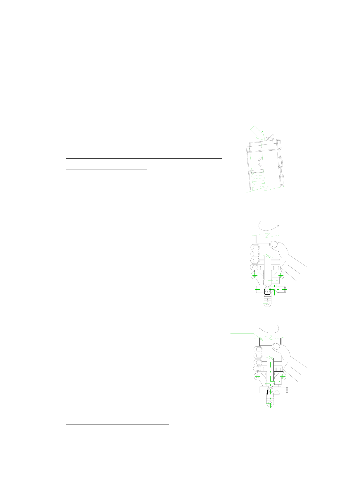
3.7 How to Replace the Cartridge (only for cartridge type models)
(1) Pull up the chain (so that a new cartridge can be inserted) and hook the
chain to the tab on the top of the cover (the point indicated by the
arrow in the drawing on the right).
(2) Turn the cover by hand and remove it from the pump.
- 6 -
(3) Remove the empty cartridge from the pump, and mount a new
cartridge paying appropriate attention so as not to allow air and foreign
substances to enter.
注意銘板
Caution
plate
* Use the same brand and same grade of grease.
(4) Mount the cover to the pump again and tighten it by hand.
(Position in which the seal comes to the front)
(5) Pull up the chain to remove from the tab and move it down slowly.
Note: Put the chain completely in the cover.
Note: For types without a spring, steps (1) and (5) are not necessary.
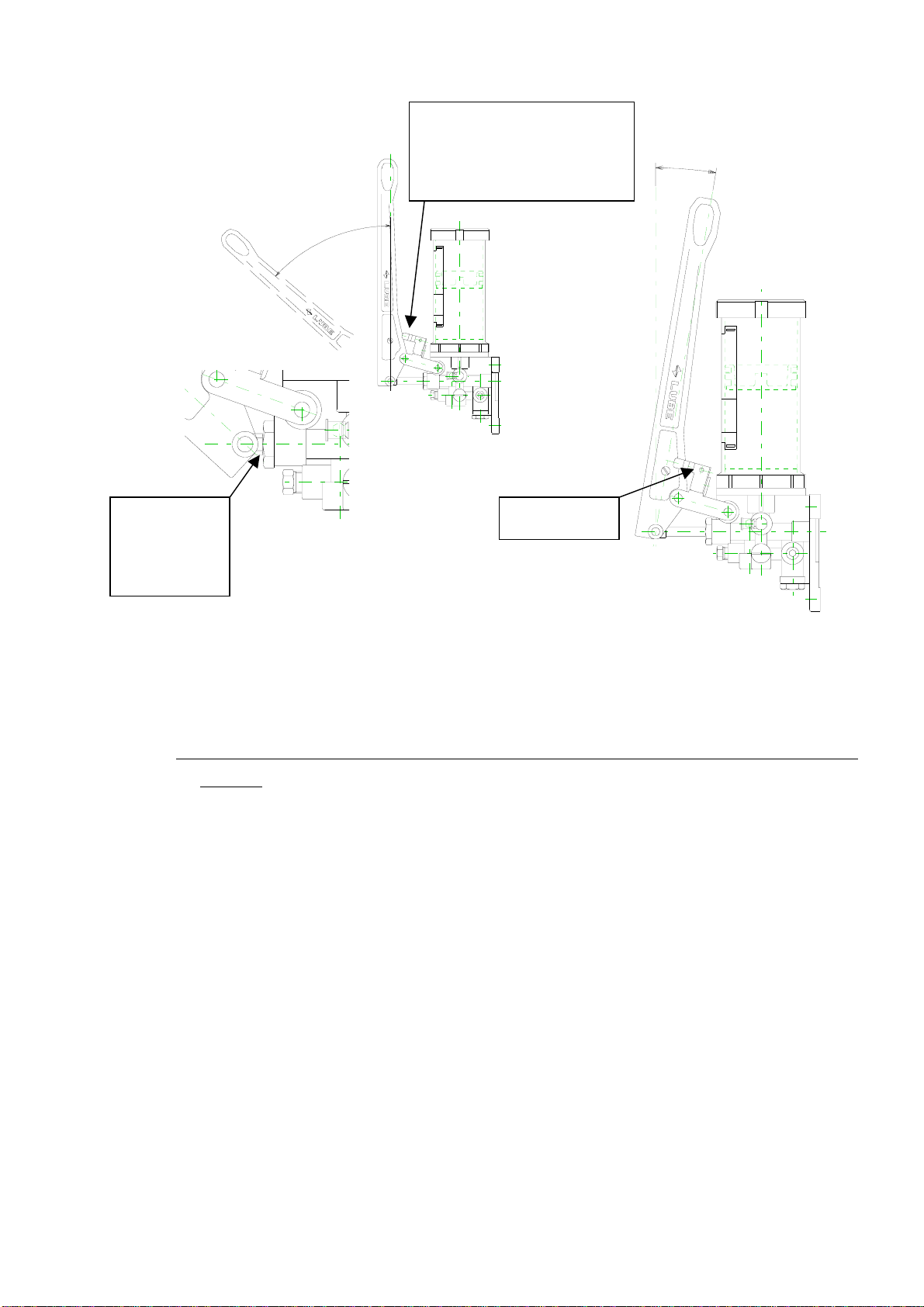
4. Pump Operation
Figure 1
Detailed drawing
(47.5゜)
(9.5゜)
During operation, if the handle touches
the handle stop, do not push in an
y
more, but pull it.
Handle stop
The piston and the
grand nut touch
each other
(1) Disengage the handle with the handle stop
(as shown in Figure 1).
Figure 2
(2) Feed grease by moving the handle to and fro.
* Pulling the handle to you sets the system to discharge operation and pushing it sets the system to sucking
operation.
(3) Grease feed operation is completed when the handle can no longer be pulled toward you. (The handle can
be pulled toward you until the stepped portion of the piston shown in Figure 1 touches the grand nut. Refer
to the detailed drawing.)
(4) When pushing the handle during operation, stop the handle when the handle touches the end of the handle
stop. (At this point, the handle is approximately parallel with the tank.)
(5) After completing grease feeding, push the handle until it comes into the status shown in Figure 2 for reducing
pressure (Figure 2). Under this status, the handle is locked to the handle stop. Then, stop pushing the
handle.
- 7 -

- 8 -
5.
Troubleshooting and Measures to take
TroubleCauseMeasures to take
Little grease left in the reservoir. Refill the reservoir or replace cartridge
with the same or equivalent grease.
Air in the pump. Bleed air.
No grease discharged
from pump
Insufficient move of the handle. Move the handle until it does
not move.
No grease discharged from pump
due to any of above causes.
Refer to above measures.
Air in the tubing. Take off closure plug(s) at the end
and operate pump and bleed air in
the tubing.
Foreign particle(s) at the Ball seating
section of relief valve.
Contact LUBE
Pump discharge pressure is low due to relief
valve’s wrong pressure setting.
Contact LUBE
The relief valve pressure has been set
before shipment.
Grease leaking from pump discharge port
or pipe connection parts.
(Due to looseness or excessive tightness)
Tighten them with proper torque or re-pipe
them.
Damaged tubing. Replace damage tubing.
Pressure in main tubing
is not built up
Handle is pushed to reservoir too much.
(Depressurize valve is opened.)
Operate the handle at correct range.
Air in the system due to above reasons. Refer to above measures for“Air in the
pump”and“Air in the tubing”.
Air in the system
Due to low level of grease in tank or
cartridge, air is introduced into pump.
Refill reservoir with same or equivale
nt grease or replace cartridge and then
bleed air.
Clogged valve(s) Replace valve(s)
No grease discharged from
valve(s) No grease is filled in tail tubing. Fill tail tubing with grease at installation.
This manual suits for next models
7
Table of contents
Other LUBE Water Pump manuals


Popular Water Pump manuals by other brands


DUROMAX
DUROMAX XP WX Series user manual

BRINKMANN PUMPS
BRINKMANN PUMPS SBF550 operating instructions

Franklin Electric
Franklin Electric IPS Installation & operation manual

Xylem
Xylem e-1532 Series instruction manual

Milton Roy
Milton Roy PRIMEROYAL instruction manual

STA-RITE
STA-RITE ST33APP owner's manual