EKKO EP20D Series User manual

The Specification
EP20D Series –Walkie Pallet Jack
Note: Before using must read this manual and the various warning label!
EKKO Material Handling Equipment Manufacturing, Inc.

Introduction
In order to meet the needs of the national environmental protection request. To reduce
industrial pollution and improve productivity, we develop new series of SL15GF walkie
Electric Pallet truck on the basis of absorption of the advantages of domestic & overseas
battery Pallet truck, they are especially suitable for cargo loading and unloading, handling,
stacking, etc of food, bank, light textile, station, port, logistics and other enterprises.
This manual describes the technical parameters of the Pallet truck, working principle and
operation, maintenance, and other aspects. It can help operators use the Pallet truck more
reasonable, make its maximum effectiveness.
Operator should strictly abide the regulations and the precautions in this manual when
using the Pallet truck. Carefully use them so that your Pallet truck can be in the best working
condition for long period of time to maximize its effectiveness. And create better economic
benefits.
The Statement
Our company production model SL type 1.5T Walkie Electric Pallet Truck is a special motor
vehicle used in factory ,tourist attractions ,amusement places which is specified by “special
equipment safety supervision regulations”

Contents
1.The Introduction .............................................................................................................1
2.Proper usage.....................................................................................................................2
Modification............................................................................................................................... 2
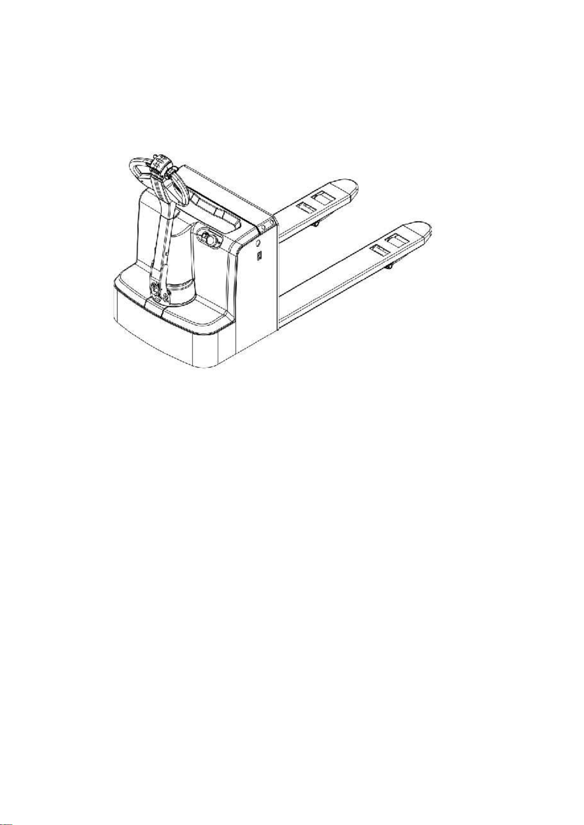
3.Introduction of the product.........................................................................................3
3.1 Model Overview................................................................................................................ 3
4.Operating principle ........................................................................................................5
5.Operating principle ........................................................................................................6
5.1Running system.................................................................................................................. 6
5.2 Steering system................................................................................................................. 6
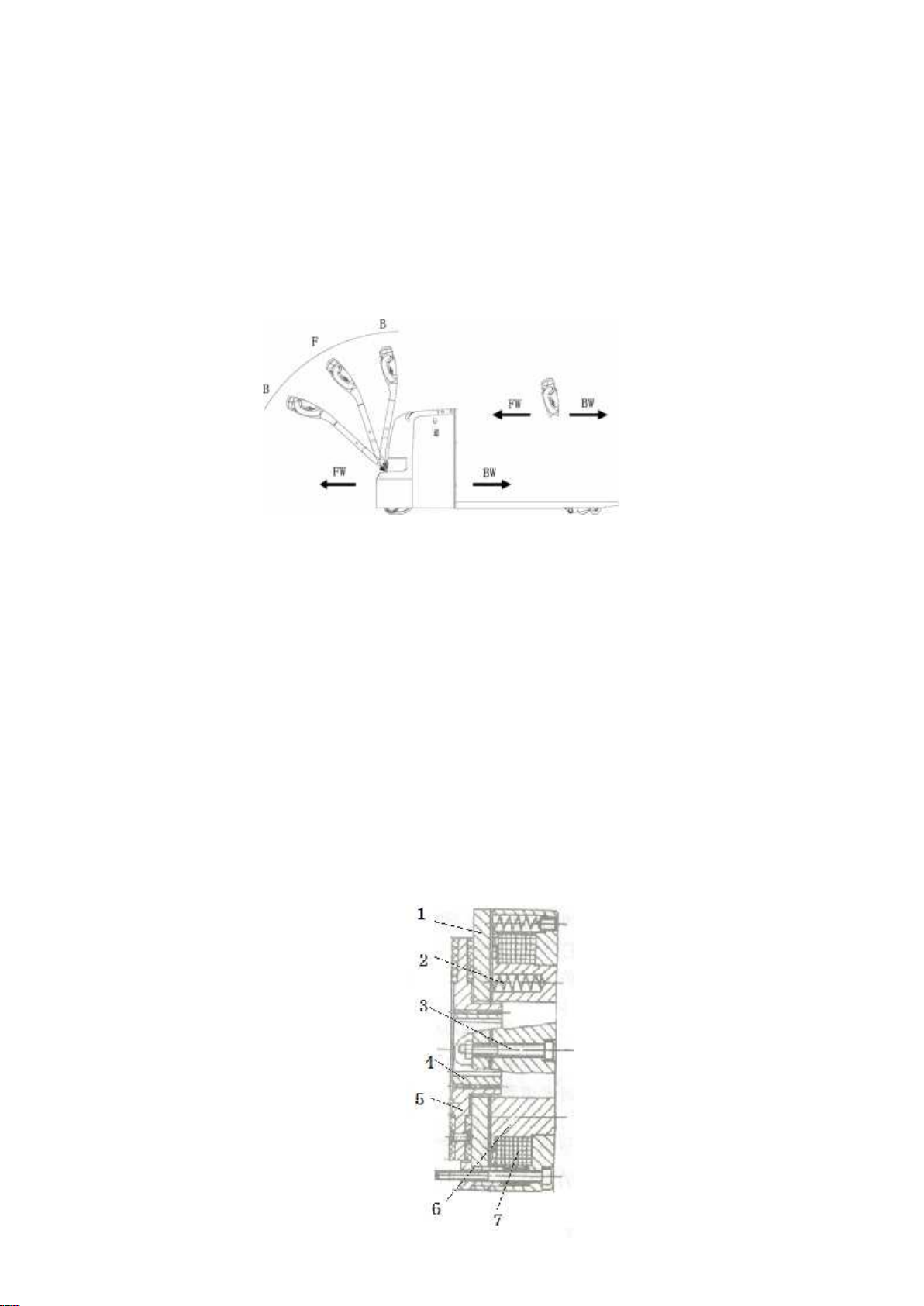
5.3 Braking system.................................................................................................................. 6
5.4 Operating System............................................................................................................. 8
5.5 Electric System.................................................................................................................. 8
5.6 Hydraulic principle.......................................................................................................... 8
6.Electrical Schematic Diagram..................................................................................... 9
7.Hydraulic Schematic Diagram ................................................................................. 10
8.Operating Instruction................................................................................................. 11
8.1 Start, run and parking: .................................................................................................11
8.2The usage of emergency safety switch....................................................................11
8.3 The usage of horn button. ...........................................................................................11
8.4 Battery capacity indicator...........................................................................................11
8.5 Handling stacking operation......................................................................................12
9.Maintenance................................................................................................................... 13
9.1Safety procedures for repair and maintenance...................................................13
9.2 Daily Maintenance .........................................................................................................14
9.3 Professional Maintenance Manual...........................................................................14
9.4Maintenance, Recharging and Replacement of the accumulator..................16
10.Safety Precautions..................................................................................................... 19
10.1 general rules..................................................................................................................19
10.2 Transportation and storage.....................................................................................19
10.3 Check before Using......................................................................................................20
10.4 Safe Operation...............................................................................................................20
11.Repair Manual ............................................................................................................ 23
11.1 Malfunction analysis...................................................................................................23
11.2 preparation work before repair.............................................................................24
11.3 check the oil content of hydraulic oil...................................................................24
11.4 preparation work before use after maintenance ............................................24

1
1.The Introduction
EP20D is a walkie type electric pallet truck. It adopts the advanced structure such as ring rod
lifting system and new ac controller, at same time it is equipped with high quality motor,
lithium battery and pump station motor. It has the characteristics of superior performance,
convenient operation, flexible steering, reliable braking, good dynamic performance, less
noise, less pollution and beautiful appearance.
This series truck is suitable for working on the smooth ground in warehouse, if not, please
don’t use it.
The service environment:
a. temperature: -10℃~ +40℃;
b. the gradient less than 3%;
c. when environment temperature at +40℃,the relative humidity should be less than
50%,At low temperature,higher humidity is allowed;
d. ground should be hard and flat;
e. It is forbidden to use this car in corrosive environment such as flammable and
explosive or acid base.

2
2.Proper usage
Please use the electric pallet truck accord to this specification.
This is a walkie type electric pallet truck with autonomous control, lifting and lowering
is controlled by the handle button. Improper use can cause personal injury or machine
damage. Operators or operating companies need to ensure proper using,
The Truck needs to be used on a firm, flat ,intact surface and suitable surface ,The truck
is designed for indoor use at room temperature from-10°C to +40°C
Use under light load without permanent barriers or pits, It is forbidden to operate on
the slopes. During Operation ,The goods must be placed approximately at the center of the
truck’s load center
Lifting or Carrying people is strictly prohibited.
It is prohibited to use this truck on lifting or loading ramps。
The rated capacity is marked on the capacity label or nameplate. And the operator must pay
attention to the warming signs and safety instructions
Operating lighting must be at least 50LUX.
Modification
Any modification that may affect the truck rated capacity, stability, or safety operations must
be approved in advance by the Truck’s original manufacturer or Its authorized Manufacturer
or its successor. This includes the effects of changes such as Braking, steering ,Visibility, and
the addition of removable accessories.
After the manufacturer or its successor approves the modification or change, The capacity
name plate, Label, identification marks, operation and maintenance manual must be changed
accordingly
3.Introduction of the product

3
3.1 Model Overview
This specification is for EP20D series 4400LBS tramp type electric pallet truck(follow as
truck).
The type is“EP20D—20 load capacity is 2T-4400LBS” meet the requirement of
JB/T8452-1996《Battery forklift model establishment method》.
3.2 Model
Mode
EP20D

4
Lift
Electric
Drive
Electric
Load Capacity
(lbs)
4400
Load centre distance
(in)
24
Wheel base
(in)
53
Lowered fork height
(in)
3.3
Lifting height
(in)
7.7
Overall length
(in)
67.2
Overall width
(in)
27.5
Fork size
(in)
2/6/48
Outside distance of fork
(in)
27
Turning radius
(in)
55
Lifting speed,laden/unladen
(in/s)
0.8/1.1
Lowering speed,laden/unladen
(in/s)
1.5/1.5
Max. Gradient performance
laden/unladen
(%)
8/15
Brake type
electromagnetic
Drive motor
kw
0.75
Lift motor
kw
0.8
Battery voltage
V/Ah
24/100
Type of the drive motor
DC Motor speed control
Noise level at operator sear
dB(A)
68
Service weight
(lbs)
750
4.Operating principle

5
With battery as power producer and controlled by electrical and hydraulic, trucks can do some
actions like walking, turning, pallet fork lift, etc.
1.Switch for lifting and lowering 2.Switch for driving 3.Belly switch
4.Horn
5.Operating principle

6
5.1Running system
The truck is powered by a battery, which is realized by controlling the AC motor on the drive
wheel. The speed of walking is realized by frequency conversion control motor speed, which is
controlled by the accelerator.
Gear box in the factory has been posited with enough gear lubricating oil. And please change
the gear lubricating oil every 1000 hours under normal circumstances.
If you hear abnormal sound from gear box when using, please stop and check immediately. If
there are bearing failure or some problem in gear, please replace and repair them.
5.2 Steering system
The operating handle drives the rotation direction sensor which can send out the turn signals that
makes the truck turn around.
5.3 Braking system
5.3.1Braking performance depends on road conditions and vehicle load
conditions.
The brake function can be activated by the following ways:
Turn the travel switch (2) to "0" position or release the switch to make truck brake
until it stops.
With the driving switch (2) moving directly from one driving direction to the
opposite direction, the vehicle regenerates the brake until it begins to move in the
opposite direction.
The handle moves up and down to the braking area (' B ') and the vehicle brakes. If
the handle is released, the handle automatically moves to the upper braking area ('
B ') and the vehicle stops until it stops.

7
Belly switch (3) can prevent the operator will be squeezed, when vehicles are
driven towards (' Fw) encounters an obstacle, body touch belly to slow down or
start to switch
vehicles (' Bw) driven a short distance, then stop. If the handle is in the operating area
and the vehicle is not moving, please consider that this is still working.
5.3.2Working principle of braking:
The brake is composed of magnetic yoke assembly 6, excitation coil 7, spring 2, brake disc 5,
armature 1, gear sleeve 4, mounting screw 3, etc. The brake is mounted on the end cover of the
motor and the mounting screw is adjusted to the specified air gap value. The gear sleeve is fixed
on the shaft, and its outer tooth is matched with the inner tooth of the brake disc. When working,
torque is transferred, and the brake disc can move axially on the gear sleeve.
When the brake excitation coil 7 is energized, the magnetic field generated by the coil
causes the armature 1 to attract to the yoke assembly 6, and the armature 1 is detached (released)
from the brake disc 5. At this time the motor drive shaft with brake disc 5 normal start and
operation. When coil 7 is cut off, the magnetic flux disappears and armature 1 is released. Spring 2
presses armature 1 and compresses the friction plate on the brake disc to generate friction, thus
achieving the braking purpose.
制动原理图

8
5.4 Operating System
The main working part of truck is fork, which are used to carry the pallet or cargo for
transport and short distance transportation. The expansion of the cylinder is realized by the
control of the operating handle, and the pressure oil is provided by the pumping station.
5.5 Electric System
The electrical system includes walking and operation control. The truck use AC electric
control assembly.。
The meter has a battery indicator. When the battery power is too low, the electric meter
will cut off the starting control line of the oil pump motor. The moving truck can only walk
without lifting the fork, and the prompt should be charged immediately. The motor of oil
pump is the dc motor for 5 minutes, so the pump motor is not suitable for long running. That
is, the lifting movement should have time interval, can not continuously carry on, otherwise
would make the motor heating, even burn.
Special note: when the truck is used for a long time, the starter of the oil pump motor
may fail, and it can't be broken after being sucked or closed. The latter is not throw control
handle, the oil pump motor is kept in the rotation, should immediately stop at this moment,
to cut off the power supply (unplug battery plug-in), make the oil pump motor stop running,
and promptly replace the starter.
5.6 Hydraulic principle
The oil pump motor drives the gear pump to provide hydraulic power, lifting oil cylinder is
responsible of fork’s lifting and lowering, The control of the lift oil road is controlled by the
buttons on the operating handle, The lifting action is controlled by a single action oil circuit
on the valve block. This model of the hydraulic system pressure can only be adjusted on the
valve block, has been debugging good, before they go out after they leave the our company
after-sales personnel or professional maintenance personnel are strictly forbidden to adjust
themselves, so as to avoid safety accident.

9
6.Electrical Schematic Diagram

10
7.Hydraulic Schematic Diagram

11
8.Operating Instruction
Before operation, please be familiar with the function of each switch/button on the
instrument panel.
8.1 Start, run and parking:
1).Insert the key into the key switch, turn to the right, pull the emergency power safety
switch up, open the control circuit.
2).Forks rise above ground about 10 cm
3).Turn on the travel switch slowly, till the requested speed
4).Any fault of the truck happening during operation, need to cut off the power immediately,
and press the red emergency power switch down.
5).Avoid take a sudden turn during driving the truck.
6).Using truck Full load climbing a slope, need to know the condition of the slope, and press
the travel switch as much as possible to get a maximum grade ability.
7).When stop driving, put the fork in the bottom, press the emergency switch down, and pull
out the key.
8.2The usage of emergency safety switch
Press the emergency safety switch down, then the truck is powered off. Method to open it:
pull the red button up.
Emergency safety switch is made of plastic, too much pressure may damage it.
8.3 The usage of horn button.
Press the horn button in the center of handle to notify people around.
8.4 Battery capacity indicator
The stacker battery capacity indicator has electricity capacity display function.

12
8.5 Handling stacking operation
1). How to transport the goods pile on weight
Will forklift drive to the front of the items which need to carry slowly , make fork parallel to
the ground, lifting the fork to height, it can be inserted into the freight insert goods fork and
move forward slowly, when the goods completely inserted into the goods after parking and
stepping on the brakes, manipulating ascend handle, the heavy lifting to a certain height,
make the door frame lean back, slowly astern, don't touch the adjacent goods, when weight
completely left the heap of goods, reduce the goods to the right position, then walk for
handling.
2). The weight on the heap of goods
Will weight low, lean back door frame, to storage goods moving close to the pile of
deceleration, when determining forklift with pile goods into a linear state, stepping on the
brakes slowly adjust the door frame Angle to the vertical state, increase the weight will be
slightly more than goods pile height, and then slowly driving forklift driving forward to pile
top stop. Heap controls control lever slowly, once handling stacked drags the weight, the
goods fork to the hollow position, from the weight of the goods fork, make sure barrier-free
backward position, can retreat. After goods fork out weight reduce goods fork, door frame
round of the reentry after handling operation.

13
9.Maintenance
The parts on the vehicle, especially safety devices, shall not be modified without permission,
and the driving speed of the vehicle shall not be changed. All parts supplied by the original
manufacturer are subject to strict quality inspection. To ensure the safety and reliability of
the vehicle, please use the original accessories. Replacement parts, including all oil, must be
collected and processed in accordance with local environmental and health laws and
regulations.
9.1Safety procedures for repair and maintenance
Maintenance technician: The maintenance and service should only be performed by
special personnel trained by the manufacturer. After the technician sent by after-sales
department of the manufacturer completed maintenance and servicing work, they should
sign on the service log.
Cleaning Operation: Flammable liquid cannot be used for cleaning the stacker. Before
cleaning, take safety precautions to prevent electric sparks (e.g. sparks caused by short
circuit). When operating the accumulator, connectors on it must be disconnected. Use soft
air suction or compressed air, non-conductive and anti-static brushes to clean electric and
electronic components.
Operation of Electric System: Operation on the electric system should only be performed
by specially trained personnel. Before performing any operation on the electric system,
precautions must be made to prevent electric shock. When operating the accumulator,
connectors on it must be disconnected.
Installation: When repairing or replacing hydraulic components, electric and electronic
components, make sure to install them back to their original positions.
Wheels: Quality of the wheels has significant effect on stability and driving performance of
the stacker. Modification on wheels can be performed only with the approval from the
manufacturer. When replacing wheels, ensure that the stacker is levelled as delivery
state(wheels must be replaced in pairs, i.e. replace right wheel together with left one).
Lifting chain and rollers: Chain and rollers will be worn quickly without good lubrication.
Perform periodic lubrication according to following maintenance table. Shorten the
lubrication period under adverse operation conditions (such as in dusty and hot
environment).
Hydraulic oil pipe: The oil pipe must be changed every 6 years. When change the hydraulic
assembled parts, the oil pipe should be also changed.

14
9.2 Daily Maintenance
9.2.1 Check every pole, every cable and their covers.
9.2.2Check if the accumulator box is secured.
9.2.3 Check the stacker for oil leakage.
9.2.4 Check the chain, rollers, fork, oil pipes and horn.
9.2.5Check the brake.
9.2.6 Check the wear and tear of drive wheels and loading wheels.
9.3 Professional Maintenance Manual
It is very important for safe operation of the truck to perform overall professional
maintenance. Failure in performing maintenance according to specified interval may cause
malfunction of the truck, and potential risk to human and equipment.
Maintenance periods listed in this manual apply to single shift a day under normal
operation conditions. If using in dusty environment, the ambient temperature varies
remarkably or in multi-shift situation, the maintenance period has to be shortened.
Maintain the truck according to following maintenance list. Maintenance periods are as
follows:
W1 = Every 50 work hours, but at least once a week.
M3 = Every 500 work hours, but at least once every three months
M6 = Every 1000 work hours, but at least once every six months
M12 = Every 2000 work hours, but at least once every 12 months
Additional operations should be performed in trial run period:
(In initial 50 – 100 working hours or after two months)
— Check the nuts on the wheels, and tighten them if necessary.
— Check the hydraulic components for leakage, and tighten them if necessary.
—Replace the hydraulic filter.

15

16
9.4Maintenance, Recharging and Replacement of the
accumulator
The truck must be parked in a safe location before any operation on the accumulator.
9.4.1 Maintenance Technician
Battery charging, maintenance and replacement must be operated by qualified professionals.
The user manual, supply preparation and charging requirements must be carefully read
before the preparation operation.
9.4.2 Fire protection measures
When operating the battery, smoking and open flame are strictly prohibited. Storage
batteries and charging should be kept away from combustible materials, and should be kept
at least 2 meters away. Places where batteries are placed should be well ventilated and
equipped with fire protection facilities.
9.4.3 Battery maintenance
1) Keep the nuts on every battery cell dry and clean. Tighten every terminal and cable end,
and brush them with grease to prevent corrosion. Naked cable ends and terminal posts
should be covered with a skid-proof insulating cover.
2) Every two cells should be well-connected. Check the nuts on each pole, if loose, tighten the
nuts.
3) Keep the surfaces of accumulator clean and dry. After the completion of recharging, clean
spilled acid with cotton yarns or brush. And clean with wet towel if necessary.
4) Over recharging and over discharging should be avoided, and fast charging and
insufficient recharging are also not allowed. Otherwise life span of the accumulator may be
affected.
5) Do not put conductive objects including metal tools on the accumulator, or short circuit or
even explosion may be caused.
6) Never spill any hazardous liquid or solid material on surfaces of the accumulator. When
using a densimeter or a thermometer, make sure the surface is clean and clear.
7) Recharge the discharged accumulator in time. Delayed recharging may damage the
accumulator. Do not delay recharging more than 24 hours. Recharging of the accumulator
may not work outdoors in cold weather. In this case, move it indoors to perform recharging.

17
8) If the accumulator will not be in use for a long time, it should be recharged and discharged
once every month and it should be fully recharged every time.
9) During recharging or using, the liquid level of electrolyte lowers because of water
evaporation, so pure water should be added. It is not allowed to add electrolyte with a
specific weight of 1.280.
10) If individual cell fails, identify the cause and repair the cell immediately. Replace the cell
when it cannot be repaired.
11) The site for recharging should be well ventilated. It is prohibited to smoke or use open
fire, avoiding the risk of hydrogen explosion.
12) The electrolyte in accumulator is toxic and corrosive. For this reason, always wear
working suit and protection glasses to protect your body from contacting the electrolyte in
accumulator.
13) If your clothes, skin or eyes are spilled with acid liquid in accumulator, flush with large
amount of clean water. For skin and eyes, flush with large amount of clean water and also
seek doctor’s treatment immediately. Acid spillage must be neutralized and treated
immediately.
14) The weight and dimensions of the accumulator have remarkable effect on stability of the
stacker. Therefore do not modify the type of accumulator without approval from the
manufacturer.
15) Never discharge in large current, for example, performs travelling and lifting
simultaneously.
9.4.4 Disposition of worn-out accumulators
Worn-out accumulators should be recycled according to local regulations, and stored in
specified zone or cast-off treatment zone. These works should be done by qualified
specialized companies.
9.4.5 Specification of the battery
Battery
Charger
Rated power:24V
Rated capacity:
100Ah
Input :195/265VAC
50/60Hz
Output :
DC24V15A
Table of contents
Other EKKO Truck manuals
Popular Truck manuals by other brands

LOADMASTER
LOADMASTER LEGACY 3 Series Preventive Maintenance Manual

Hoppe
Hoppe AUDIO MINI Installation instructions & owner's manual

RAM Commercial
RAM Commercial PROMASTER 2022 owner's manual

Terex
Terex TR45 Service manual

HOMCOM
HOMCOM 370-177 Assembly instruction

Komatsu
Komatsu HD1500-7 - Operation & maintenance manual