EL-CELL PAT-Chamber-16 C User manual
© 2017 EL-CELL GmbH
User Manual
Release 1.0
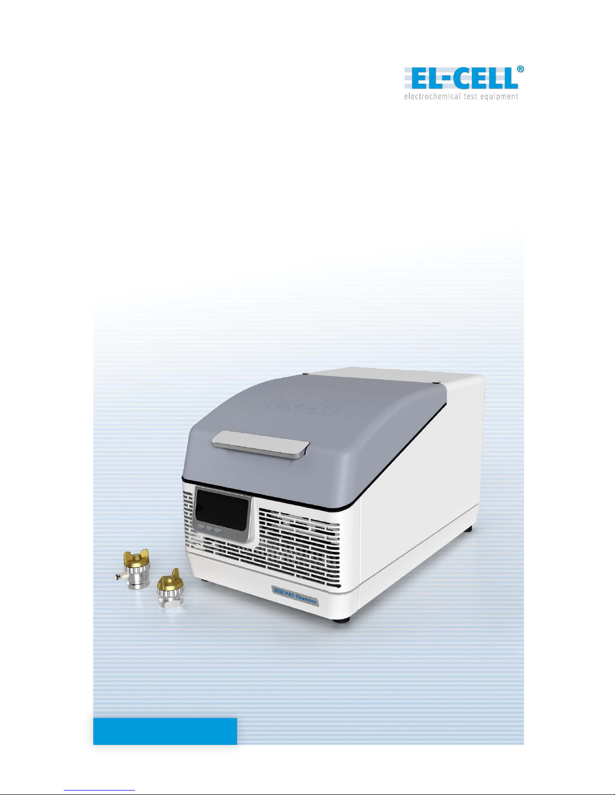
PAT-Chamber-16 / PAT-Chamber-16 C
Temperature-controlled docking station

Page 2 of 16
Release 1.0
User Manual PAT-Chamber-16
The information in this manual has been carefully checked and believed to be accurate;
however, no responsibility is assumed for inaccuracies.
EL-CELL GmbH maintains the right to make changes without further notice to products
described in this manual to improve reliability, function, or design. EL-CELL GmbH does not
assume any liability arising from the use or application of this product.
EL-CELL GmbH
Tempowerkring 8
21079 Hamburg - Germany
phone: +49 40 79012-737
fax: +49 40 79012-736
e-mail: info@el-cell.com
web: www.el-cell.com

Page 3 of 16
Release 1.0
User Manual PAT-Chamber-16
Content
1 Product description ...................................................................................................................................... 4
2 Safety instructions......................................................................................................................................... 5
3 Technical data ................................................................................................................................................ 6
4 Installation....................................................................................................................................................... 8
5 Operation ......................................................................................................................................................10
6 EC-Link software ..........................................................................................................................................12
7 Cleaning .........................................................................................................................................................12
8 Unpacking .....................................................................................................................................................12
10 EC declaration of conformity .................................................................................................................13
11 Technical support......................................................................................................................................16
12 Warranty ......................................................................................................................................................16
Included component manuals
PAT-Connect-16..…….……………………………………………………………………………………………………………………….
EC-Link software……………………………………………………………………………………………………………………………….

Page 4 of 16
Release 1.0
User Manual PAT-Chamber-16
1Product description
The PAT-Chamber-16 is a temperature controlled docking station / cell chamber for up to 16
test cells of the PAT series. The temperature of the chamber can be precisely controlled by
means of a Peltier device between 5 and 80°C. The PAT-Chamber-16 is the first high
throughput docking station supporting the PAT-Cell-Press for in-situ pressure monitoring of
up to 16 test cells at the same time.
The PAT-Chamber-16 is to be connected to a multi-channel potentiostat (like the Biologic
MPG-2) or battery tester (like the Maccor 4000). Mixed connection of the 16 cell positions to
different potentiostats / battery testers is possible as well.
The PAT-Chamber-16 features a built-in data logger for recording all cell signals –cell current,
cell voltage and the two half cell voltages of each cell –along with the chamber temperature
and the individual pressure signals, if used with the PAT-Cell-Press.
The PAT-Cell, the PAT-Core, and the EC-Link data logger software are covered in detail by
other manuals (http://el-cell.com/downloads/downloads-manuals).
PAT-Chamber-16 and PAT-Chamber-16 C (with integrated PAT-Connect adapter box)
Features
Peltier temperature-controlled docking station, ready for connection to any potentiostat
or battery tester.
Temperature range 10 –80°C
Holds up to 16 PAT series test cells for 2- and 3-electrode measurements.
Charge/discharge/EIS compatible with any PAT series test cell
Supports up to 16 PAT-Cell-Press for additional pressure monitoring
Compatible with all of today's multi-channel potentiostats and battery testers. Mixed
operation of the 16 cell positions with different potentiostats and/or battery testers
possible.
Integrated data logger hard- and software for recording of cell current, cell voltage, half
cell voltages, global temperature, and individual cell pressure.
Analog outputs available of the buffered half cell voltages (16 x V2R), sensor signals
(16 x AOUT) and chamber temperature (VT). The analog outputs allow for easy
interfacing with the external inputs of the connected battery tester / potentiostat.

Page 5 of 16
Release 1.0
User Manual PAT-Chamber-16
2 Safety instructions
The PAT-Chamber-16 should only be operated by laboratory personnel especially trained for
this purpose and familiar with all precautionary measures required for working in a laboratory .
To avoid injuries and damage observe the safety instructions of this user manual.
NOTE: The PAT-Chamber-16 must only be used with test cells of the PAT series. Don’t place other
goods inside the chamber.
2.1Localization / position of safety labels on the PAT-Chamber-16
The following lables are located on the unit
Electrical hazard!
After removing covers, live parts may be exposed. You may receive
an electric shock if you touch these parts. Disconnect the mains plug
before removing any covers. Only electrical technicians may work on
the electrical equipment of the appliances.
Hot surface!
The parts of the inner chamber will become hot during operation.
Danger of burning. Do not touch the inner surfaces during operation
without protective gloves.
Wear protective gloves
Page 6 of 16
Release 1.0
User Manual PAT-Chamber-16
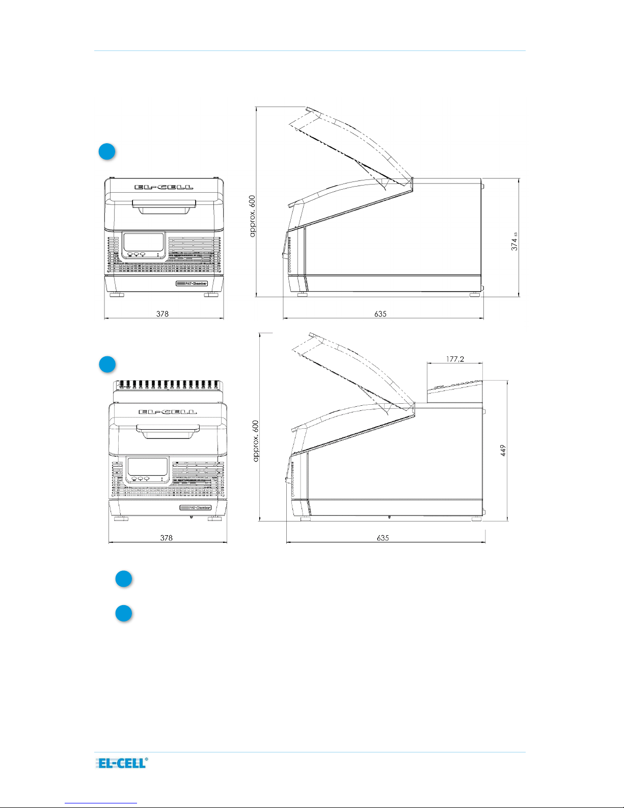
3Technical data
Dimensions:
635 mm (width) x 378 mm (depth) x 374 mm (height)
Dimensions with attached PAT-Connect-16 C:
635 mm (width) x 378 mm (depth) x 449 mm (height)
Temperature: +10 to +80°C
Weight: 24 kg (without PAT-Cells)
1
2
1
2
Page 7 of 16
Release 1.0
User Manual PAT-Chamber-16
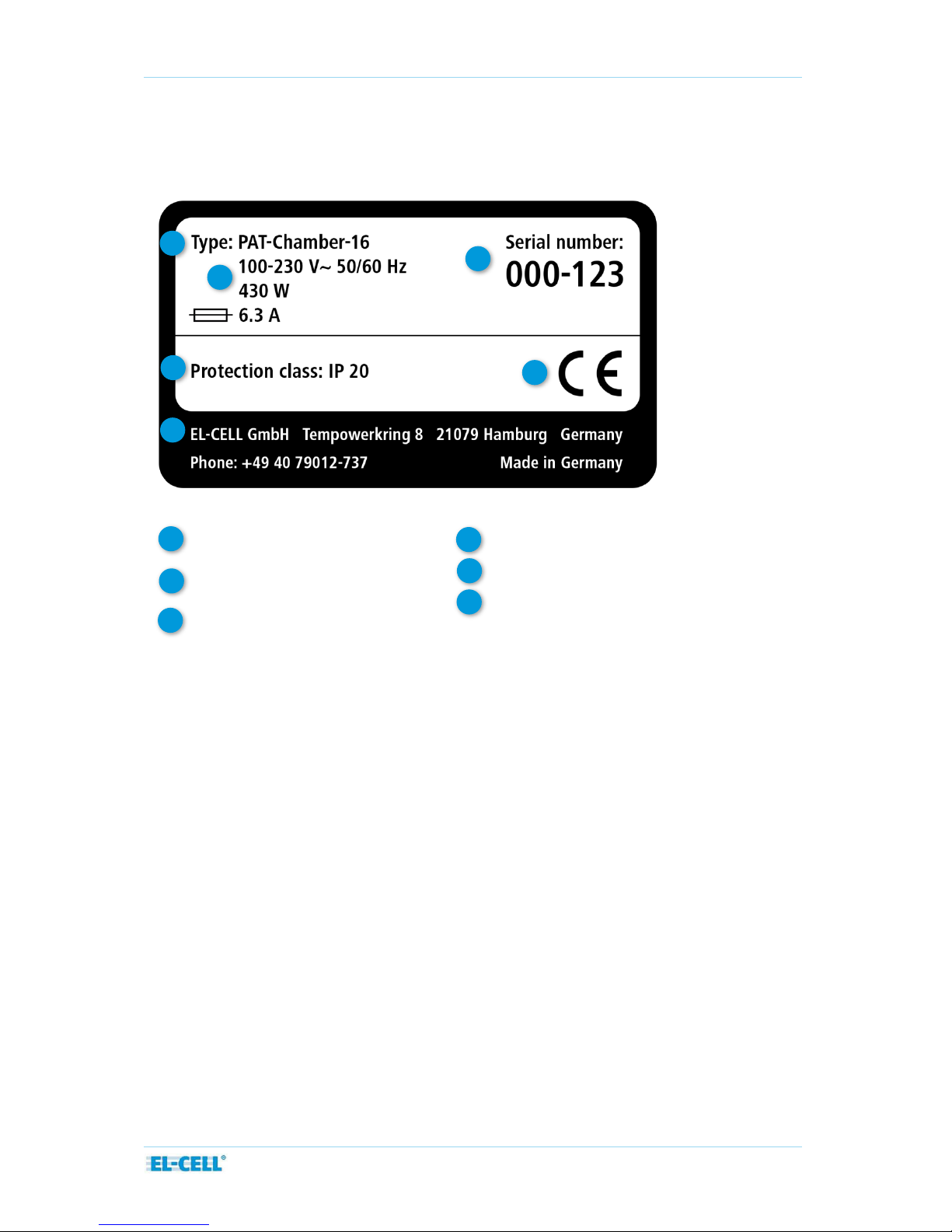
3.1 Designation (nameplate)
The nameplate provides information about the appliance model, manufacturer and technical
data. It is attached to the back of the appliance.
1
2
5
3
6
Type designation
Operating voltage,
Connection / power ratings
Protection class
1
3
2
Address of manufacturer
Serial number
CE conformity
4
6
5
4
Page 8 of 16
Release 1.0
User Manual PAT-Chamber-16
4Installation
Place the PAT-Chamber-16 on a flat, horizontal surface. Do not place the instrument on a
flammable surface. A 230 V or 115 V power connection must be available. The distance
between the wall and the rear of the instrument must be at least 15 cm. The top clearance
must not be less than 25 cm. Sufficient air circulation in the vicinity of the instrument must be
guaranteed at all times.
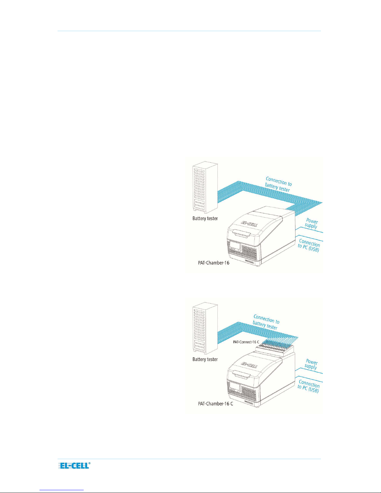
4.1 Connection to the external battery tester or potentiostat
Two versions of the PAT-Chamber-16 are available which differ in the way the connection to
the external battery tester or potentiostat is being established.
1. PAT-Chamber-16:
Direct connection with fixed
assignment of WE, CE and RE for a
given channel.
2. PAT-Chamber-16 C:
Indirect connection via
PAT-Connect-16 C with variable
assignment of WE, CE and RE for a
given channel.

Page 9 of 16
Release 1.0
User Manual PAT-Chamber-16
4.2 Connection to the power supply
Caution:
Observe the country-specific regulations when making connections. Observe the connection
and power ratings (see nameplate.). Make sure to establish a safe PE conductor connection.
Plug the provided power cable into the rear of the instrument. Lay the power cable so that it
is always accessible and within reach so it can be disconnected quickly in the event of failure
or emergencies.
Connect the other end of the power cable to the power supply (wall outlet). The instrument
will immediately power up once connected. Note that the cells docked into the PAT-Chamber-
16 will experience self-discharge (across a resistance of approx. 10 kOhm between WE and CE)
in case the instrument is powered down.
4.3 USB connection to the host PC
Plug one end of the provided USB cable into the USB socket at the rear of the PAT-Chamber-
16, the other end into the USB socket of the Windows PC. From the provided CD, install the
EC-Link software on the Windows PC and launch the EC-Link software.
For details of the software installation and operation, refer to the EC-Link software manual.
Note that the USB data logger hardware of the PAT-Chamber-16 is powered from the host PC,
and is galvanically isolated from the power supply of the PAT-Chamber.
Page 10 of 16
Release 1.0
User Manual PAT-Chamber-16
5 Operation
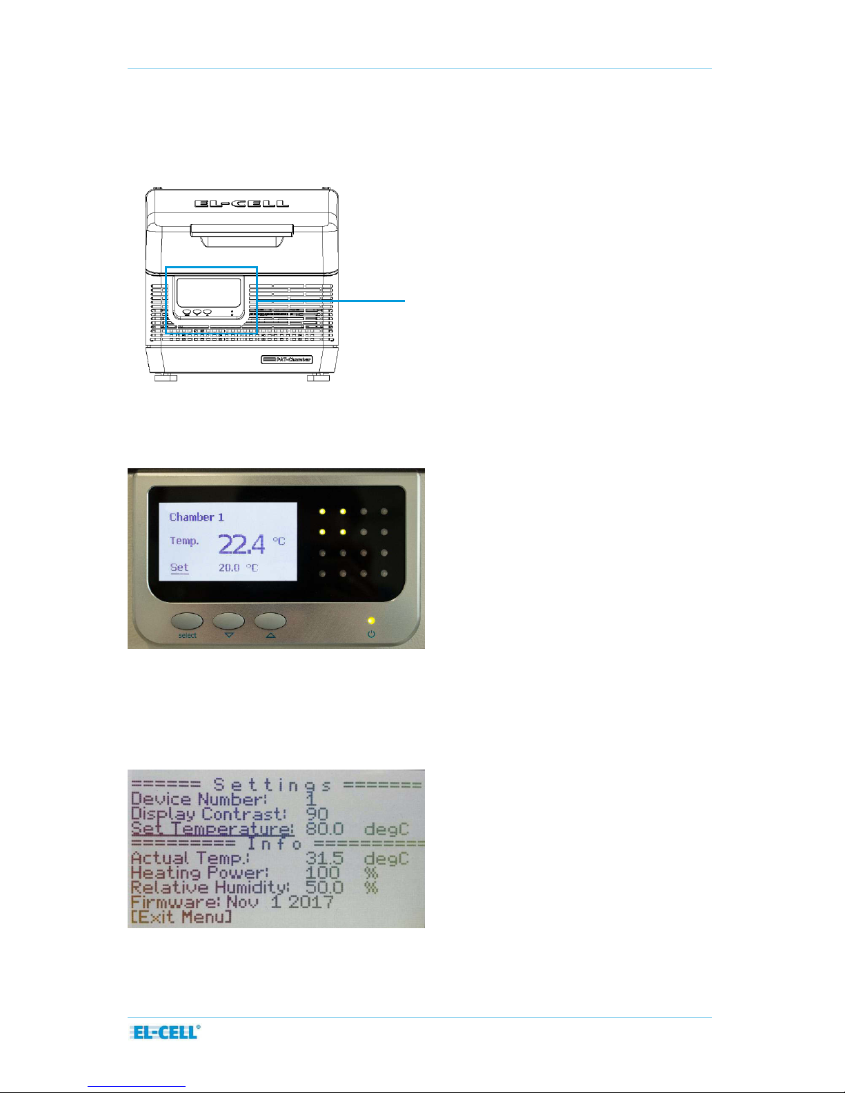
5.1 Control display, push buttons, and LED matrix
By default, the LC display at the front of the PAT-Chamber-16 shows the actual and the
setpoint temperature. The 4x4 LED matrix on the right informs about whether the
corresponding cell socket is free (LED off) or occupied (LED lit).
In order to change the setpoint temperature, press the select button, then adjust the
displayed setpoint with the arrow buttons, and confirm with the select button.
In order to change the device number or the display contrast, hold the select button for at
least one second. A settings list shows up. From this list, select the device or contrast entry
with the arrow buttons and change as required.
Control display
Page 11 of 16
Release 1.0
User Manual PAT-Chamber-16
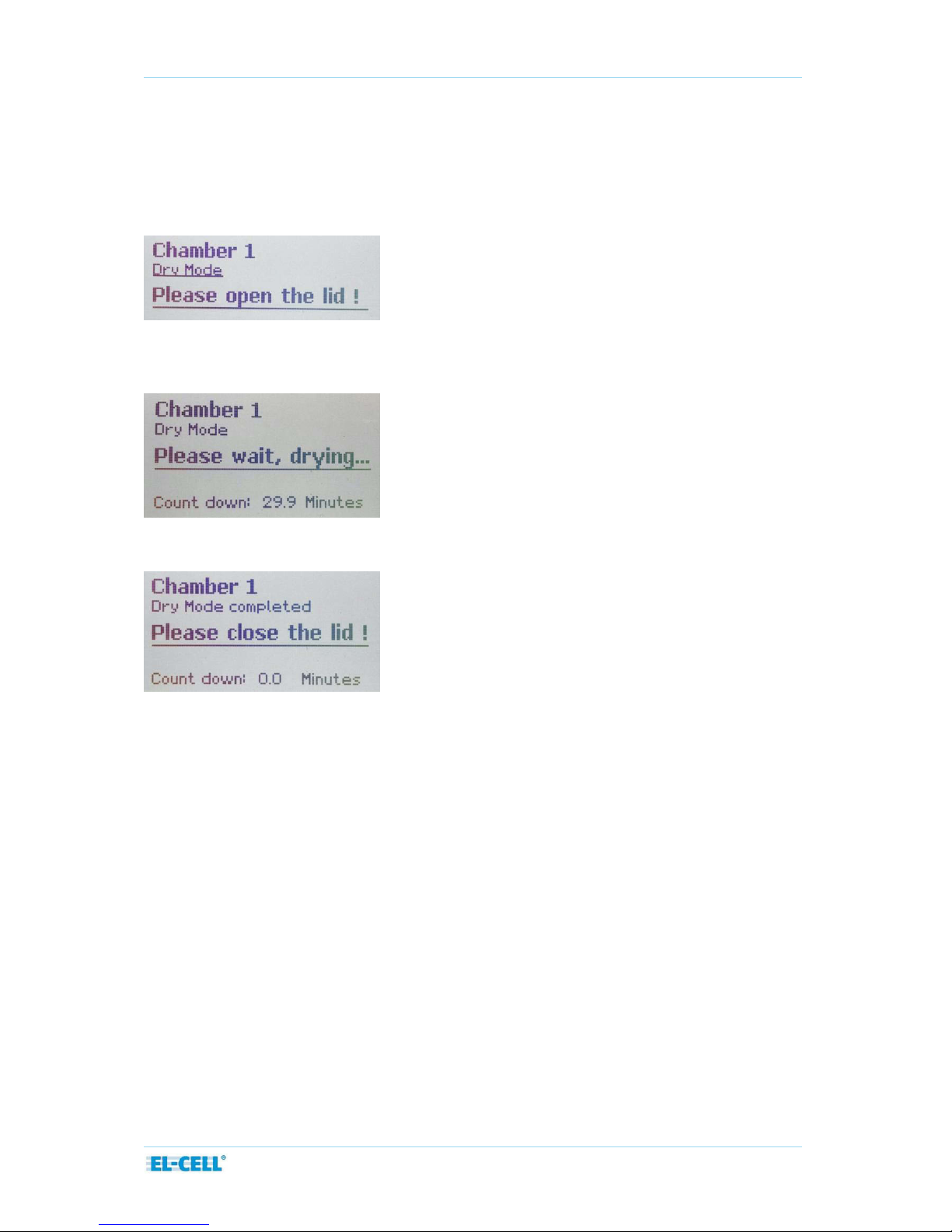
5.2 Dry Mode
Under certain operating conditions, especially when heating up the chamber from a setpoint
below ambient temperature, water may start to condense inside the chamber. When detecting
such an operating condition, the chamber automatically enters the so -called Dry Mode: The user
is prompted to open the lid of the PAT-Chamber.
Once the lid has been opened, the user is prompted to wait (to leave the chamber open) for a
given time period.
Once the countdown is finished, the user is prompted to close the lid.
5.2 Workflow
This section gives a quick overview on how to run a test with a PAT-Cell docked into the PAT-
Chamber, and connected to an external battery tester. More details on the EC-Link software
are given in a separate manual.
─Open the cover of the PAT-Chamber
─Insert a new PAT-Cell into a free socket, and close the cover.
─In EC-Link, a menu pops up, notifying that a new test cell has been inserted.
─Follow the instructions of the ‘New cell detected’ dialog. Data recording for the given
cell will be started.
─In the software application of the battery tester, start the test procedure of the
corresponding channel.
─Once the test is completed, remove the PAT-Cell from the PAT-Chamber.
─In EC-Link, a menu pops up, notifying that recording has been stopped.

Page 12 of 16
Release 1.0
User Manual PAT-Chamber-16
6EC-Link software
How to install and operate with the EC-Link software is described in a separate manual.
Please note that the EC-Link software is only required for the standard configuration of the
PAT-Chamber-16, which contains a data logger. A passive version of the PAT-Chamber-16
without a data logger is available on request.
7Cleaning
Wipe the PAT-Chamber-16 with a moist tissue. Do not use aggressive chemicals for cleaning.
Protect the PAT-Chamber-16 from dust and splash water.
8Unpacking
Check the contents of the packages against the list given below to verify that you have
received all of the required components. Contact EL-CELL, if anything is missing or damaged.
NOTE: Damaged shipments must remain within the original packaging for freight company
inspection.
List of components
PAT-Chamber-16 ECC1-03-0300-A
optionally with PAT-Connect-16 C ECC1-03-0130-A
Power cord ELT9412
USB cable (Type A/B; 2,0m) ELT9167
EC-Link installation CD ECE1-00-0052-A
NOTE: The cables for connection between PAT-Chamber-16 and the external battery tester
must be ordered separately.
Page 13 of 16
Release 1.0
User Manual PAT-Chamber-16
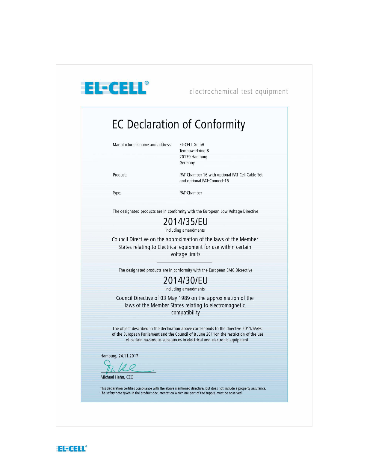
10 EC declaration of conformity

Page 14 of 16
Release 1.0
User Manual PAT-Chamber-16
The products described are in conformity with the following harmonized standards:
EN 61010-1:2010
Sicherheitsbestimmungen für elektrische Mess-, Steuer-,
Regel- und Laborgeräte –Teil 1: Allgemeine Anforderungen
(DIN EN 61010-1, VDE 0411-1:2011-07)
Safety requirements for electrical equipment for
measurement, control and laboratory use - Part 1: General
requirements
(IEC 61010-1:2010 + Cor. :2011)
EN 61010-2-201:2014
Sicherheitsbestimmungen für elektrische Mess-, Steuer-,
Regel- und Laborgeräte - Teil 2-201: Besondere
Anforderungen für Steuer- und Regelgeräte
(DIN EN 61010-2-201:2014, VDE 0411-2-201:2014-01)
Safety requirements for electrical equipment for
measurement, control and laboratory use - Part 2-201:
Particular requirements for control equipment
(IEC 61010-2-201:2013)
EN 61010-2-010:2015-05
Sicherheitsbestimmungen für elektrische Mess-, Steuer-,
Regel- und Laborgeräte - Teil 2-010: Besondere
Anforderungen an Laborgeräte für das Erhitzen von Stoffen
(DIN EN 61010-2-010:2014; VDE 0411-2-010:2015-05)
Safety requirements for electrical equipment for
measurement, control and laboratory use - Part 2-201:
Particular requirements for control equipment
(IEC 61010-2-201:2013)
EN 61326-1:2013
Elektrische Mess-, Steuer-, Regel- und Laborgeräte - EMV-
Anforderungen - Teil 1: Allgemeine Anforderungen
(DIN EN 61326-1:2013-07, VDE 0843-20-1:2013-07)
EMC requirements - Part 2-3: Particular requirements - Test
configuration, operational conditions and performance criteria
for transducers with integrated or remote signal conditioning
(IEC 61326-2-3:2012)

Page 15 of 16
Release 1.0
User Manual PAT-Chamber-16
EN 61326-2-3:2013-07
Elektrische Mess-, Steuer-, Regel- und Laborgeräte - EMV-
Anforderungen - Teil 2-3: Besondere Anforderungen -
Prüfanordnung, Betriebsbedingungen und Leistungsmerkmale
für Messgrößenumformer mit integrierter oder abgesetzter
Signalaufbereitung
(DIN EN 61326-2-3:2013-07, VDE 0843-20-2-3:2013-07)
Electrical equipment for measurement, control and laboratory
use - EMC requirements - Part 2-3: Particular requirements -
Test configuration, operational conditions and performance
criteria for transducers with integrated or remote signal
conditioning
(IEC 61326-2-3:2012)
EN 50581: 2013-02
Technische Dokumentation zur Beurteilung von Elektro- und
Elektronikgeräten hinsichtlich der Beschränkung gefährlicher
Stoffe
(DIN EN 50581; VDE 0042-12:2013-02)
Technical documentation for the assessment of electrical and
electronic products with respect to the restriction of
hazardous substances

Page 16 of 16
Release 1.0
User Manual PAT-Chamber-16
11 Technical support
Technical support for this product is exclusively provided by EL-CELL GmbH.
EL-CELL GmbH
Tempowerkring 8
21079 Hamburg - Germany
phone: +49 40 79012-737
fax: +49 40 79012-736
e-mail: info@el-cell.com
web: www.el-cell.com
12 Warranty
For a period of one year from the date of shipment, EL-CELL GmbH (hereinafter Seller)
warrants the goods to be free from defect in material and workmanship to the original
purchaser. During the warranty period, Seller agrees to repair or replace defective and/or
nonconforming goods or parts without charge for material or labor, or, at the Seller’s option,
demand return of the goods and tender repayment of the price. Buyer’s exclusive remedy is
repair or replacement of defective and nonconforming goods, or, at Seller’s option, the
repayment of the price.
Seller excludes and disclaims any liability for lost profits, personal injury, interruption of
service, or for consequential incidental or special damages arising out of, resulting from, or
relating in any manner to these goods.
This Limited Warranty does not cover defects, damage, or nonconformity resulting from
abuse, misuse, neglect, lack of reasonable care, modification, or the attachment of improper
devices to the goods. This Limited Warranty does not cover expendable items. This warranty is
void when repairs are performed by a non-authorized person or service center. At Seller’s
option, repairs or replacements will be made on site or at the factory. If repairs or
replacements are to be made at the factory, Buyer shall return the goods prepaid and bear all
the risks of loss until delivered to the factory. If Seller returns the goods, they will be delivered
prepaid and Seller will bear all risks of loss until delivery to Buyer. Buyer and Seller agree that
this Limited Warranty shall be governed by and construed in accordance with the laws of
Germany.
The warranties contained in this agreement are in lieu of all other warranties expressed or
implied, including the warranties of merchantability and fitness for a particular purpose.
This Limited Warranty supersedes all prior proposals or representations oral or written and
constitutes the entire understanding regarding the warranties made by Seller to Buyer. This
Limited Warranty may not be expanded or modified except in writing signed b y the parties
hereto.

© 2017 EL-CELL GmbH
User Manual
Release 1.0
PAT-Connect-16
Adapter box for flexible wiring connections

Page 2 of 10
Release 1.0
User Manual PAT-Connect-16
The information in this manual has been carefully checked and believed to be accurate;
however, no responsibility is assumed for inaccuracies.
EL-CELL GmbH maintains the right to make changes without further notice to products
described in this manual to improve reliability, function, or design. EL-CELL GmbH does not
assume any liability arising from the use or application of this product.
EL-CELL GmbH
Tempowerkring 8
21079 Hamburg - Germany
phone: +49 40 79012-737
fax: +49 40 79012-736
e-mail: info@el-cell.com
web: www.el-cell.com

Page 3 of 10
Release 1.0
User Manual PAT-Connect-16
Content
1 Product description ...................................................................................................................................... 4
2 Technical data ................................................................................................................................................ 5
3 Installation....................................................................................................................................................... 6
4 Cleaning ........................................................................................................................................................... 8
5 Unpacking ....................................................................................................................................................... 9
6 Accessories ...................................................................................................................................................... 9
7 Technical support ........................................................................................................................................10
8 Warranty ........................................................................................................................................................10
Page 4 of 10
Release 1.0
User Manual PAT-Connect-16
1Product description
The PAT-Connect-16 box serves the most flexible connection between an external battery
tester or multi-channel potentiostat and the PAT-Stand-16/PAT-Chamber-16. The individual
connection between a given PAT-Cell in the stand /chamber and the corresponding channel of
the battery tester can be configured via an array of banana sockets at the front of the
connection box. That gives the largest possible freedom to choose between the various full
and half cell control modes.
In addition, the PAT-Connect box feeds through all the auxiliary analog signals provided by
the PAT series test cells - temperature, pressure and buffered half cell voltages - and makes
these signals available to the external battery tester.
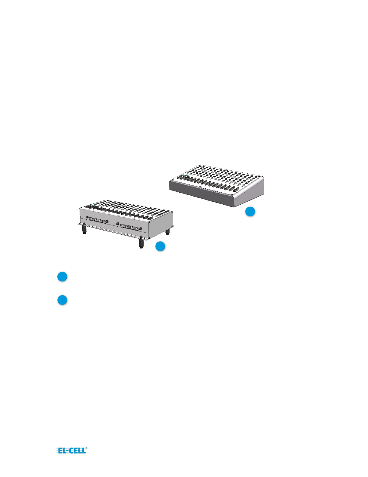
Two different versions of the PAT-Connect-16 are available:
The PAT-Connect-16 for connection to the PAT-Stand-16. This version is for wall
mounting or placing on the bench.
The PAT-Connect-16 C for connection to the PAT-Chamber-16. This version is
permanently attached to the PAT-Chamber.
Features
Easy-to-access banana sockets for plug-in of the cell cables of the battery tester /
potentiostat (sockets available for WE, WE-Sense, RE, CE, CE-Sense, and GND)
Sub-D Connector for optional auxiliary signals: buffered half cell voltages, temperature,
sensor signals
Available as modular box (PAT-Connect-16) to be placed on the bench or fixed on the
wall, or as an attachment on top of the PAT-Chamber-16 C (PAT-Connect-16 C)
PAT-Connect-16-C
PAT-Connect-16
1
1
2
2
This manual suits for next models
1
Table of contents
Other EL-CELL Docking Station manuals


