EL GENS LPC-2C M Series User manual

LPC-2CxM Series P-cap Panel PC
LGA1151 9th/8th Gen., Core-i7/5/3
User Manual
Published in Taiwan
Release Date : Nov 2022
Revision : V0.1

ELGENS CO., LTD. 2LPC P-cap 2CxM Series User Manual
Warning!
This equipment generates, uses and can radiate radio frequency energy and if not installed and used in
accordance with the instruction manual, it may cause interference to radio communications. It has been
tested and found to comply with the limits for a Class A computing device pursuant to FCC Rules, which
are designed to provide reasonable protection against such interference when operated in a commercial
environment. Operation of this equipment in a residential area is likely to cause interference in which
case the user at his own expense will be required to take whatever measures may be required to correct
the interference.
Electric Shock Hazard – Do not operate the machine with its back cover removed. There are dangerous
high voltages inside.
Disclaimer
This information in this document is subject to change without notice. In no event shall ELGENS Co., Ltd.
be liable for damages of any kind, whether incidental or consequential, arising from either the use or
misuse of information in this document or in any related materials.
Packing List
Accessories (as ticked) included in this package are:
□Panel Mounting Kits
□3 Pin Male Terminal Block
□Optional Adapter
□Other.___________________(please specify)
Safety Precautions
Follow the messages below to avoid your systems from damage:
◆ Avoid your system from static electricity on all occasions.
◆ Prevent electric shock. Don‘t touch any components of this card when the card is power-on.
Always disconnect power when the system is not in use.
◆ Disconnect power when you change any hardware devices. For instance, when you connect a
jumper or install any cards, a surge of power may damage the electronic components or the
whole system.

ELGENS CO., LTD. 3LPC P-cap 2CxM Series User Manual
Table of Contents
Chapter 1 Getting Started..............................................................5
Brief Description of LPC P-cap 2CxM Series.....................................................................................5
System Specifications ......................................................................................................................5
Naming Rule.....................................................................................................................................7
Dimension........................................................................................................................................9
Top / Bottom IO View ....................................................................................................................10
Motherboard Layout......................................................................................................................11
Chapter 2 Installation .............................................................. 13
Remove Heatsink...........................................................................................................................13
Installation of DRAM......................................................................................................................14
Installation of HDD.........................................................................................................................15
Installation of Low-Profile PCI-Express Cards ................................................................................17
Chapter 3 UEFI SETUP UTILITY ................................................. 19
Entering and Control......................................................................................................................19
Main...............................................................................................................................................21
System Date .............................................................................................................................................21
System Time.............................................................................................................................................21
Advanced .......................................................................................................................................22
3.3.1 CPU Configuration ..............................................................................................................23
3.3.2 Chipset Configuration.........................................................................................................25
3.3.3 PCI/PCIE Device Configuration............................................................................................27
3.3.4 Super IO Configuration .......................................................................................................28
3.3.5 AMT Configuration..............................................................................................................29
3.3.6 ACPI Configuration..............................................................................................................31
3.3.7 USB Configuration...............................................................................................................32
3.3.8 Trusted Computing .............................................................................................................33
Hardware Health Event Monitoring Screen...................................................................................34
Security ..........................................................................................................................................35
Boot ...............................................................................................................................................36
3.6.1 CSM (Compatibility Support Module) ................................................................................37
Exit .................................................................................................................................................38
Chapter 4 Installation Drivers...................................................... 39
Chipset Driver Installation .............................................................................................................39
4.1.1 Select “INF(v10.1.17968.8131_Public) ” folder and execute “Setupchipset.exe”..............39
4.1.2 Please follow the red blank. ...............................................................................................39
Graphics Driver Setup....................................................................................................................42

ELGENS CO., LTD. 4LPC P-cap 2CxM Series User Manual
4.2.1 Select “ VGA(v25.20.100.6617)” folder and execute “igxpin.exe” .....................................42
4.2.2 Please follow the red blank. ...............................................................................................42
Audio Driver Setup.........................................................................................................................46
4.3.1 Select “Audio 9057_FF00” folder and execute “Setup.exe”...............................................46
4.3.2 Please follow the red blank. ...............................................................................................46
LAN Driver Setup............................................................................................................................48
4.4.1 Go to ”Intel_LAN(v23.5.2) ” folder and choose ” Autorun.exe”.........................................48
4.4.2 Please follow the red blank. ...............................................................................................48
ME Driver Setup.............................................................................................................................51
4.5.1 Go to “ME(v12.0.2.1087_Corp)” and choose ”SetupME.exe” ...........................................51
4.5.2 Please follow the red blank. ...............................................................................................51
History............................................................................................. 54

ELGENS CO., LTD. 5LPC P-cap 2CxM Series User Manual
Chapter 1 Getting Started
Brief Description of LPC P-cap 2CxM Series
The LPC P-cap 2CxM series is a power-optimized and delivers robust performance-per-watt for
embedded HMI, powered by an up to TDP 35W Intel 9th/8th Gen., Core-i7/5/3/Celeron processors
with Q370 PCH. It comes with a Bezel-Free design, M.2 Key-M slot and an Internal 2.5-inch
storage bay, up to 64GB DDR4-2666 memory, 1 PCIex16 slot, 3 DP1.2 ports, audio jack, 2
Ethernet, and 4 USB 3.1 ports. The unit supports Windows 10 operation system.
The Elgens’ fanless touch panel computer is ideal for use as Web Browser, Terminal, HMI at all
levels of automation control or a high-performance system that working on rash environment.
System Specifications
Model Number
LPC-P150S-2CxM
Max Resolution
1024*768
Color
16.7M
Luminance
400 nits
View Angle (H/V)
160/140
Contrast Ratio
800
Computing
Processor
Socket LGA 1151 for 9th/8th Intel® Core i7/i5/i3/Celeron (Supports up to
35W)
System Memory
2 x SO-DIMM, up to 64 GB DDR4-2666
Intel® Core i3/Pentium®/Celeron® CPUs support up to 32GB (16GB per
DIMM)
Storage
1 x Internal 2.5” Storage Bay
1 x M.2 Key-M slot
External I/O
Port
4 x USB 3.1 Gen1
2 x GbE LAN ( Intel® I219LM & Intel® I210 )
3 x Display Port
2 x RS-232
1 x Audio out
1 x Mic in
1 x Power press button
1 x 3-Pin Power Input
Expansion Slots
1 x PCIe x16 Slot
OS support
Windows 10
Touch Screen
Type
USB P-cap Touch

ELGENS CO., LTD. 6LPC P-cap 2CxM Series User Manual
Light
Transmission
Up to 90%
Power Supply
Power Input
◼DC12V or DC19V~28V Power Input
◼3-Pins Terminal Block or 4-Pins DC Jack
Mechanical
Construction
Aluminum Heatsink and Metal Case
IP Rating
Front Panel compliant IP65
Mounting
Panel Mount & VESA
Environmental
Operating
Temperature
-30~70 °C
Storage
Temperature
-30~70 °C
Storage
Humidity
10~90% @40 °C non-condensing

ELGENS CO., LTD. 7LPC P-cap 2CxM Series User Manual
Naming Rule
Order Information
LPC-Pxxxx-2C3M
Bezel-Free P-cap Panel PC with 9th Gen., Core i3 CPU, DC 12V Power Input,
including a 3-Pin Power Adapter
LPC-Pxxxx-2C5M
Bezel-Free P-cap Panel PC with 9th Gen., Core i5, DC 12V Power Input,
including a 3-Pin Power Adapter
LPC-Pxxxx-2C7M
Bezel-Free P-cap Panel PC with 9th Gen., Core i7, DC 12V Power Input,
including a 3-Pin Power Adapter
WFK-024
Wi-Fi kits w/ cable & Antenna (2.4GHz, 802.11 b/g/n, 1T1R)
WFK-524
Wi-Fi kits w/ cable & Antenna (2.4 & 5GHz, 802.11 a/b/g/n/ac + BT, 2T2R)
Order Code

ELGENS CO., LTD. 8LPC P-cap 2CxM Series User Manual
LPC-PxxxS/W
-H / -OB / -AG / -AR / -B / -V
P = P-Cap touch
B = Glass without touch
xxx = size, For example, 10.1” = 101
S = Dimension Ratio Square = 4:3 or 5:4
W= Dimension Ration Wide = 16:9 or 16:10
H = High Brightness 1000 nits LED backlight (Optional, up to 1600 nits backlight, by LCD limited)
OB = Optical Bonding (Optional)
AG = Anti-Glare (Optional)
AR = Anti-Reflection (Optional)
V = Vandal Proof Glass (Optional)

ELGENS CO., LTD. 9LPC P-cap 2CxM Series User Manual
Dimension
LPC-P150S-2CxM Drawing

ELGENS CO., LTD. 10 LPC P-cap 2CxM Series User Manual
Top / Bottom IO View
Top View
Bottom View

ELGENS CO., LTD. 11 LPC P-cap 2CxM Series User Manual
Motherboard Layout
It may cause system/board damage if change the Jumper/Connector setting.
Please do NOT change the setting if you are not very clear to know the
Jumper/Connector used for.

ELGENS CO., LTD. 12 LPC P-cap 2CxM Series User Manual
1 : USB2.0 Header (USB2_4_5)
2 : USB2.0 Header (USB2_6_7)
3 : System Panel Header
4 : PWR_BAT2
5 : Buzzer
6 : BLT_PWM1
7 : SATA Power Output Connector
8 : Digital Input / Output Pin Header (JGPIO1)
9 : Digital Input / Output Power Select (JGPIO_PWR1)
10 : Digital Input / Output Default Value Setting (JGPIO_SET1)
11 : COM Port Headers (COM1, 2, 3, 4)
12 : COM Port PWR Setting Jumpers (SET_CM1, 2, 3, 4)
13 : Backlight Power Select (LCD_BLT_VCC) (BKT_PWR1)
14 : Backlight Power Connector (BLT_PWR1)
15 : BL1
16* : LVDS Panel Connector
* eDP Connector (on the Backside of PCB)
17 : LVDS Switch (LVDS_SWITCH1)
18 : BL2
19 : ATX/AT Mode Jumper (SIO_AT1)
20 : Panel Power Select (LCD_VCC) (PNL_PWR1)
21 : Backlight Volume Control (BLT_VOL1)
22 : Chassis Intrusion Header (Cl2)
23 : Chassis Intrusion Header (CI1)
24 : Clear CMOS Headers (CLRMOS1, CLRMOS2)
25 : 4-pin UPS Module Power Input Connector (Input +12V & +19V~+28V)
26 : 3W Audio AMP Output Wafer
27 : ATX Power Connector (Input +12V & +19V~+28V)
28 : 2-pin UPS Module Power Input Connector
29 : Front Panel Audio Header
30 : SPDIF Header
31 : CPU FAN Connector (+12V)
32 : Chassis FAN Connector (+12V)
33 : SATA3 Connectors (SATA3_1, SATA3_2)
34 : LPC Header

ELGENS CO., LTD. 13 LPC P-cap 2CxM Series User Manual
Chapter 2 Installation
The LPC 2CxM series is a panel pc with Mini-ITX motherboard. Before you install the
accessories on motherboard, study the installation guide to ensure that the accessories be
secured.
Remove Heatsink
The heatsink cover is secured onto the chassis with 18 M3*5 zinc-coated screws located at
4 sides. Use a Phillips screwdriver to unscrew them.
Step 1. Loosen screws as below picture
Step 2. You can access internal accessories while you pull the heatsink and Left/Right sides
brackets.
1. Remove all power source before you start to remove heatsink.
2. It is easy to cause damage after the heatsink had removed. Please be carefully do
not drop tools and/or parts on it while heatsink had removed.
3. Make sure all parts and screws are secured before you cover up.

ELGENS CO., LTD. 14 LPC P-cap 2CxM Series User Manual
Installation of DRAM
Step 1. Following CH2.1 to remove heatsink.
Step 2. Align a SO-DIMM on the slot such that the notch on the SO-DIMM matches the break on
the slot.
Step 3. Firmly insert the SO-DIMM into the slot until the retaining clips at both ends fully snap
back in place and the SO-DIMM is properly seated.
1. The SO-DIMM only fits in one correct orientation. It will cause permanent damage to
the motherboard and the SO-DIMM if you force the SO-DIMM into the slot at
incorrect orientation.
2. Please do not intermix different voltage SO-DIMMs on this motherboard.

ELGENS CO., LTD. 15 LPC P-cap 2CxM Series User Manual
Installation of HDD
Step 1. Following CH2.1 to open case.
Step 2. Screwed Storage on bracket
Step 3. Screwed the assembled parts of step2 into system

ELGENS CO., LTD. 16 LPC P-cap 2CxM Series User Manual
Step 4. Connect storage Cables with Boards

ELGENS CO., LTD. 17 LPC P-cap 2CxM Series User Manual
Installation of Low-Profile PCI-Express Cards
Step 1. Following CH2.1 to open case.
Step 2. Loosen screws to remove cover brackets.
Step 3. Plug Low-Profile PCI-Express cards into slot.

ELGENS CO., LTD. 18 LPC P-cap 2CxM Series User Manual
Step 4. Make sure the card’s bracket had plugged into groove and screw in the three M3*5
screws tight to secure the add-on cards.

ELGENS CO., LTD. 19 LPC P-cap 2CxM Series User Manual
Chapter 3 UEFI SETUP UTILITY
This section explains how to use the UEFI SETUP UTILITY (also names BIOS) to configure your
system. The UEFI chip on the motherboard stores the UEFI SETUP UTILITY. You may run the UEFI
SETUP UTILITY when you start up the computer. Please press
<F2> or <Del> during the Power-On-Self-Test (POST) to enter the UEFI SETUP UTILITY, otherwise,
POST will continue with its test routines.
If you wish to enter the UEFI SETUP UTILITY after POST, restart the system by pressing <Ctl> +
<Alt> + <Delete>, or by pressing the reset button on the system chassis. You may also restart by
turning the system off and then back on.
Entering and Control
Power on the computer and the system will start POST (Power-On Self Test) process. When the
message below appears on the screen, press <DEL> or <F2> key to enter Setup.
Press <DEL> or <F2> to enter SETUP
If the message disappears before you respond and you still wish to enter Setup, restart the
system by turning it OFF and On or pressing the RESET button. You may also restart the system
by simultaneously pressing <Ctrl>, <Alt>, and <Delete> keys.
Important
The items under each BIOS category described in this chapter are under continuous update for
better system performance. Therefore, the description may be slightly different from the latest
BIOS and should be held for reference only.
Wrong Setting values in this section may cause the system malfunctions.

ELGENS CO., LTD. 20 LPC P-cap 2CxM Series User Manual
Control Keys
← →
Select Screen
↑ ↓
Select Item
Enter
Select
+ -
Change Option
F1
General Help
F7
Previous Values
F9
Optimized Defaults
F10
Save & Restart
F12
Print screen
Esc
Exit
Getting Help
After entering the Setup menu, the first menu you will see is the Main Menu.
Main Menu
The main menu lists the setup functions you can make changes to. You can use the arrow keys
( ↑↓ ) to select the item. The on-line description of the highlighted setup function is displayed
at the bottom of the screen.
Sub-Menu
If you find a right pointer symbol appears to the left of certain fields that means a sub-menu
can be launched from this field. A sub-menu contains additional options for a field parameter.
You can use arrow keys ( ↑↓ ) to highlight the field and press <Enter> to call up the sub-menu.
Then you can use the control keys to enter values and move from field to field within a sub-
menu. If you want to return to the main menu, just press the <Esc >.
General Help <F1>
The BIOS setup program provides a General Help screen. You can call up this screen from any
menu by simply pressing <F1>. The Help screen lists the appropriate keys to use and the possible
selections for the highlighted item. Press <Esc> to exit the Help screen.
This manual suits for next models
1
Table of contents
Other EL GENS Touch Panel manuals
Popular Touch Panel manuals by other brands
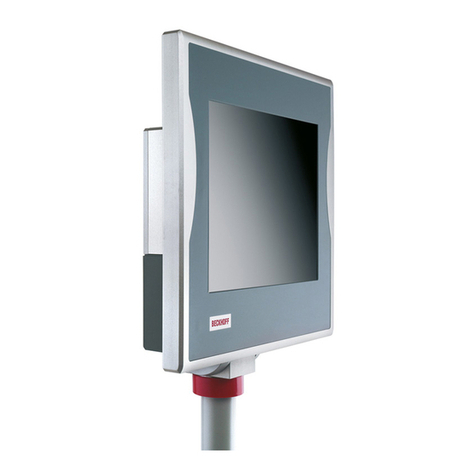
Beckhoff
Beckhoff CP72 Series Installation and operating instructions
Acnodes
Acnodes PC 8170 Specifications

Preco
Preco PreView WD7102 operating manual

RaycoWylie
RaycoWylie i3500 instruction manual
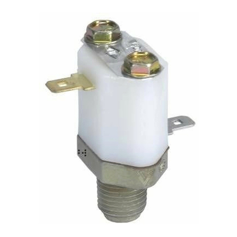
BENDIX
BENDIX LOW PRESSURE INDICATORS manual

Hakko Electronics
Hakko Electronics Monitouch V Series Reference manual
Icop
Icop PDX2-090T-5A user manual
SELECTRONIX
SELECTRONIX SUPERSTEP SERIES 4000 Startup configuration modification guide
Lex System
Lex System SUPER Series Assembly guide
panel
panel PSG3-EP Series user manual
Digital Touch Systems
Digital Touch Systems Drafting Table Assembly instructions

Avalue Technology
Avalue Technology ARC-10W33 Quick reference guide

