EL.MO. Spa NG-TRX LUPUS2K User manual

TECHNICAL MANUAL
LUPUS2K - VOLANS2K
AND BROWN VERSIONS
Radio transmitters for wireless NG-TRX
intrusion detection systems
090001113
IT08020000001624

LUPUS2K - VOLANS2K - TECHNICAL MANUAL - 090001113
elmospa.com
2
This product needs batteries for correct functioning. Exhausted batteries have to be delivered to dumping grounds
authorized for battery collection. The materials used for this product are very harmful and polluting if dispersed in the
environment.
EU DECLARATION OF CONFORMITY
DISPOSAL INSTRUCTIONS - INFORMATION FOR THE USER
FOREWORD
FOR THE INSTALLER:
Comply strictly with current standards governing the installation of electrical systems and security systems, and with the manufacturer’s
directions given in the manuals supplied with the products.
Provide the user with full information on using the system installed and on its limitations, pointing out that there are different levels of security
performance that will need to suit the user’s requirements within the constraints of the specific applicable standards. See that the user looks
through the warnings given herein.
FOR THE USER:
Check the system’s operation thoroughly at regular intervals, making sure the equipment can be armed and disarmed properly.
Make sure the system receives proper routine maintenance, employing the services of specialist personnel who meet the requirements
prescribed by current regulations.
Ask your installer to check that the system suits changing operating conditions (e.g. changes in the extent of the areas to be protected, change
in access methods, etc...).
-------------------------------
This device has been designed, built and tested with the utmost care and attention, adopting test and inspection procedures in accordance
with current legislation. Full compliance of the working specifications is only achieved in the event the device is used solely for its intended
purpose, namely:
The device is not intended for any use other than the above and hence its correct functioning in such cases cannot be assured.
Consequently, any use of the manual in your possession for any purpose other than those for which it was compiled - namely for the purpose
of explaining the product’s technical features and operating procedures - is strictly prohibited.
Production processes are closely monitored in order to prevent faults and malfunctions. However, the componentry adopted is subject to an
extremely modest percentage of faults, which is nonetheless the case with any electronic or mechanical product.
Given the intended use of this item (protection of property and people), we invite you to adapt the level of protection offered by the system to
suit the actual situation of risk (allowing for the possibility of impaired system operation due to faults or other problems), while reminding you
that there are specific standards for the design and production of systems intended for this kind of application.
We hereby advise you (the system’s operator) to see that the system receives regular routine maintenance, at least in accordance with
the provisions of current legislation, and also check on as regular a basis as the risk involved requires that the system in question is
operating properly, with particular reference to the control unit, sensors, sounders, dialler(s) and any other device connected. You must
let the installer know how well the system seems to be operating, based on the results of periodic checks, without delay.
Work involved in the design, installation and maintenance of systems incorporating this product should be performed only by personnel
with suitable skills and knowledge required to work safely so as to prevent any accidents. It is vital that systems be installed in accordance
with current legislation. The internal parts of certain equipment are connected to the mains and therefore there is a risk of electrocution
when maintenance work is performed inside without first disconnecting the primary and emergency power supplies. Certain products include
batteries, rechargeable or otherwise, as an emergency backup power supply. If connected incorrectly, they may cause damage to the product
or property, and may endanger the operator (explosion and fire).
In accordance with Directive 2012/19/EU on waste electrical and electronic equipment (WEEE), please be advised that
the EEE was placed on the market after 13 August 2005 and must be disposed of separately from normal household
waste.
IT08020000001624
Hereby, EL.MO. S.p.A. declares that the radio equipment LUPUS2K - VOLANS2K is in compliance with Directive 2014/53/
EU. The full text of the EU declaration of conformity is available at the following Internet address: elmospa.com – registration
is quick and easy.
Radio transmitters for wireless NG-TRX intrusion detection systems

090001113 - TECHNICAL MANUAL - LUPUS2K - VOLANS2K
elmospa.com
3
1. GENERALS
LUPUS2K and VOLANS2K are compact transmitters used for the control of fixtures or for perimetral protections. These
transmitters can be integrated in wireless systems managed by VIDOMO2K and VICOMPACT2K control units (belonging to
the NG-TRX system) or by other expressly compatible control unit models.
Their general features can be summarized as follows:
• LUPUS2K can transmit the state variations of magnetic contacts and of the roll-up shutter sensor wired to its terminals.
LUPUS2K is identified by the control unit as a multi-channel device; it occupies up to 3 zones for the transmission
of the anomaly/alarm states of the REED magnetic contact (located on housing side), the magnetic contact wired to
the terminal board and the roll-up shutter detector connected to the proper terminal. For the latter, you can properly
configure the number of pulses in a time slot. The detector is fully configurable via software.
• VOLANS2K can transmit the state variations of magnetic contacts and of the roll-up shutter sensor connected via
wires to its terminals. VOLANS2K is identified by the control unit as a multi-channel device; it occupies up to 4
zones for the transmission of the anomaly/alarm states of the REED magnetic contact (located on housing side), the
magnetic contact wired to the terminal board, the roll-up shutter detector connected to its related terminal and the
built-in inertial piezo sensor. You can properly configure the number of pulses in a time slot and the integration for the
roll-up shutter detector and the piezo sensor. The detector is fully configurable via software; only the sensitivity is
adjustable on the device itself.
The plastic housing features a design in line with current style trends.
Upon request, the “M” brown version is also available.
Note: the operative range for these devices is evaluated in open field with no obstacles, nevertheless the actual range
might be reduced in case the device is installed in indoor locations with peculiar architectural features. For further details,
consult the features table.
The autonomy is in the order of years of functioning, according to the features of each device.
LUPUS2K and VOLANS2K are IMQ - Security Systems certified.
2. FEATURES
Model LUPUS2K VOLANS2K
Protection class IP3X
IMQ certified EN50131-2-6: grade 2,
EN50131-5-3 (1)
Environmental class 2
Power supply voltage 3.6 V supplied by 1/2 AA 3.6 V lithium battery mod. ER14250 (supplied as standard eq.)
Low battery threshold 2.5 V with recovery to 2.9 V.
Minimum operating
voltage
2 V for the transmitter;
2.7 V for the LED indicator.
Power consumption @
3.6 V
8 µA idle,
23 mA max.
10 µA idle,
23 mA max.
TX frequency
3 channels (configurable via browser): 868.120 MHz, 868.820 MHz, 869.525 MHz for LPD devices.
Maximum transmitted
power
25 mW
Connection range
nominal/maximum
800 / 1900 m in open field; the range is subject to limitations depending on environmental
conditions. See note.
Note: the ranges refer to 99% reception of the transmitted packets, with the devices
in open field at an height of 1,5 m from the ground, respectively without and with the
orientation of the antenna in the best direction.
The activation of the “tx boost” option, if available, increases the effective range
between 10 and 30% but can significantly affect the battery life.

LUPUS2K - VOLANS2K - TECHNICAL MANUAL - 090001113
elmospa.com
4
Model LUPUS2K VOLANS2K
Average autonomy 5 years. 4 years.
Note: for the calculation, 20 total transmissions per day and a supervision transmission
every 20 min were considered.
Zones Managed as channels.
Tamper zone with NC terminals.
CH1: On-board magnetic contact.
CH2: NC zone for external magnetic contact.
CH3: NC zone for roll-up shutter detector.
Channels 2 and 3 can be configured via
software application (see “10. ELECTRICAL
CONNECTIONS”).
Managed as channels.
Tamper zone with NC terminals.
CH1: On-board magnetic contact.
CH2: NC zone for external magnetic contact.
CH3: NC zone for roll-up shutter detector.
CH4: built-in piezo sensor.
Channels 2, 3 and 4 can be configured via
software application, (see “10. ELECTRICAL
CONNECTIONS”).
Special operating
features and controls
Piezo sensor included in the printed circuit
board, with impact sensitivity control and
LED indicator for detected pulses.
The sensitivity can be adjusted using the on-
board trimmer; the integration can be set via
software application.
Wiring length with 2 ×
0.22 mm2 cable
Roll-up shutter zone: 1 or 8 m, configurable via software application;
magnetic contact zone: 20 m max.
Selections On-board REED magnetic contact enabling (on one side only).
LED indications Blue front LED. Yellow front LED, used also for piezo sensor
pulses visualization.
LED exclusion Via software application.
Sound signalling Built-in buzzer. It can be activated for alarm also in Walk test mode.
Supervision TX From 5 to 240 min (default) step between two consecutive supervision transmissions. It
can be modified via software application.
TX encoding The transmitter is provided with an identification code randomly chosen in test phase
among 2 milliard combinations (231).
Transmissions for Supervision (periodic, with step configurable via software application);
tamper events for housing opening;
low battery state;
alarm/reset for zones with magnetic contact;
alarm for roll-up shutter or piezo detector zones.
Operating temperature -10 / +55 °C guaranteed by manufacturer - 93 % Rh.
Dimensions Transmitter: W 150 × H 33 × D 39 mm;
magnet: W 47 × H 18.5 × D 15 mm.
Weight 75 g (battery and magnet). 79 g (battery and magnet).
Parts supplied 4 self tapping screw 2.9 × 13, 1/2 AA 3.6 V lithium battery mod. ER14250 to be installed
in the transmitter, magnet, technical manual.
(1) grade 1 if supervision time is set as lower than 60 min; grade 2 if supervision time is set as lower than 20 min
LUPUS2K and VOLANS2K are accessories for VIDOMO2K and VICOMPACT2K control units belonging to the Villeggio NG-TRX
system, and for other expressly compatible devices.
These transmitters are suitable for indoor installation only. Do not install them in locations where they may be
affected by condensation phenomena, for example directly on balconies.

090001113 - TECHNICAL MANUAL - LUPUS2K - VOLANS2K
elmospa.com
5
3. MECHANICAL FEATURES
View of the transmitter plastic housing and of the external magnet.
4. HOW TO DISTINGUISH THE DEVICES
The following picture shows the differences between the two transmitters.
DIMENSIONS IN mm
COUNTERSUNK
HOLES
COUNTERSUNK
HOLES
HOLE FOR
CABLE FEEDING
BLUE LED FOR
OPERATION VISUALIZATION
AND TRANSMISSION
PIEZO SENSOR (AND
RELATIVE TERMINAL)
NOT MOUNTED
IDENTIFYING LABEL
STUCK ON THE
HOUSING SIDE
IDENTIFYING LABEL
STUCK ON THE
HOUSING SIDE
YELLOW LED FOR VISUALIZATION
OF THE DETECTED PULSES
AND TRANSMISSION
TRIMMER FOR ADJUSTING
IMPACT SENSITIVITY
THE BATTERY IS SUPPLIED
AS STANDARD EQUIPMENT,
INCLUDED IN THE PACKAGE.
AFTER INSTALLING THE DEVICE,
INSERT THE BATTERY BETWEEN
THE INDICATED CLIP TABS,
PAYING ATTENTION TO
RESPECT THE POLARITY.
DO NOT TOUCH THE BATTERY
POLES WITH THE FINGERS
DURING THIS PHASE.

LUPUS2K - VOLANS2K - TECHNICAL MANUAL - 090001113
elmospa.com
6
5. HOUSING OPENING AND CLOSING
Perform the following basic operations in order to open and close the transmitter housing.
Opening.
Closing.
6. FIRST POWER-ON OR BATTERY REPLACEMENT
Particular care is required during first powering. The operations to be performed are listed in the next steps:
1. Insert the 3.6 V battery (supplied as standard equipment) checking the correct polarity.
2. Press and release the Tamper button 3-4 times.
3. Reset any memory of low battery on the control unit or on the compatible receiving device.
WARNING: in case you use a new battery or a battery that has not been used for a long time, a wrong indication of
low battery may occur at first activations. Such issue is related to the chemical features of Lithium Thionyl Chloride
batteries and it can be solved implementing the above operations.
In case of usage in low temperature locations, we suggest that you keep the battery at room temperature before
insertion.
LEAN THE COVER HERE
IN ORDER TO ACCURATELY HOOK
THE TWO CLIPS CLOSE TO THE BATTERY
UNDERLYING SURFACE FOR THE PIEZO SENSOR
ACCURATELY
HOOK THE
FRONT CLIP
MAKE SURE THE TAMPER SPRING
PROPERLY FITS IN THE BLOCKING
POSITION ON THE COVER
MAKE SURE THE LED PROPERLY
FITS IN THE HOLE ON THE COVER

090001113 - TECHNICAL MANUAL - LUPUS2K - VOLANS2K
elmospa.com
7
7. INSTALLATION
The installer shall verify that no electrostatic charges are present upon housing
opening; internal electronic boards and accessory components may be damaged
by such charges.
The same care shall be used during installation, updates and maintenance
procedures.
The detector installation must comply with certain rules in order to avoid performance drops due to positioning errors.
Indeed, it is very important to define with the utmost care the operating area of the receiving system in which the detector is
installed, the actual coverage of the sensors and the correct installation, especially in relation to the nature of the materials
used in the building construction.
The following pictures show correct and wrong installation positions, objects that may attenuate RF signals and attenuation
in some building materials.
Installing situations:
Radio signal attenuation in some typical building materials:
WIRELESS CONTROL UNIT INSTALLED
IN DECENTRALIZED POSITION.
THE SENSORS TRANSMITTERS
POSITIONED AT THE OPPOSITE
SIDE OF THE HOUSE MAY BE TOO
FAR. THE RADIO SIGNAL MAY BE WEAK
BECAUSE OF ARCHITECTURAL
OBSTACLES.
WIRELESS CONTROL UNIT INSTALLED
IN CENTRAL POSITION RESPECT TO
THE SPACE TO SUPERVISE.
THIS POSITION ALLOWS TO
REDUCETHE DISTANCE
OF PERIPHERAL DEVICES.
DO NOT POSITION THE
WIRELESS CONTROL UNIT
BELOW GROUND LEVEL.
THE RECEIVER AND THE
TRANSMITTER SENSITIVITY
WILL BE CONSIDERABLY REDUCED.
POSITION THE
WIRELESS CONTROL UNIT
HIGHER THAN GROUND LEVEL.
THE RECEIVER AND THE
TRANSMITTER SENSITIVITY
WILL TEND TOWARDS THE MAXIMUM.

LUPUS2K - VOLANS2K - TECHNICAL MANUAL - 090001113
elmospa.com
8
Objects that can modify and/or reduce the range (example with a Villeggio NG-TRX control unit):
The device is not suitable for installation on doors/windows that are opened very often (more than 100 activations each
day), since this may cause a great amount of radio transmissions and the premature battery fail.
8. COVERAGE AND SENSITIVITY
Before installing the VOLANS2K sensor, carefully consider the
maximum sensitivity that can be obtained based on the surface to be
protected with its integrated piezo sensor.
For this purpose it is useful to refer to the following table:
Surface material Radius
Brick wall 1 m
Steel 3 m
Wood 3 m
Concrete 30 cm
Plywood 3 m
Glass * 3 m
* The glass test was conducted after sticking the sensor with very
adhesive double-sided tape. When installed on glass surfaces, the
VOLANS2K transmitter is suitable for detecting impact but not for
cuts and perforations.
METAL GRIDS AND
REINFORCED
CONCRETE WALLS
METAL DOORS
MIRRORS
VIDOMO2K OR VICOMPACT2K
CONTROL UNIT
IR DETECTOR
MOD.
SCORPIO2K
THE CONTROL UNIT CAN ALSO MANAGE
ACCESSORY DEVICES BELONGING TO
STANDARD VILLEGGIO AND HELIOS SERIES
SELF-POWERED
WIRELESS SIREN WITH
LITHIUM BATTERY PACK
MOD. GAIA2K
1
2
BIDIRECTIONAL
REMOTE CONTROL
MOD. ATLANTE2K
S2
S3
S1
S4
OUTDOOR
TRANSMITTER
WITH BUILT-IN
MAGNETIC CONTACT
MOD. VIRGO2K
DT DETECTOR
MOD. CONDOR2K
TRANSMITTER WITH
BUILT-IN MAGNETIC
CONTACT, PIEZO SENSOR
AND INPUT FOR EXTERNAL
ROLL-UP SHUTTER SENSOR
MOD. VOLANSC2K
TRANSMITTER WITH
BUILT-IN MAGNETIC
CONTACT AND INPUT
FOR EXTERNAL ROLL-UP
SHUTTER SENSOR
MOD. LUPUSC2K
TRANSMITTER WITH
BUILT-IN MAGNETIC
CONTACT AND INPUTS
FOR EXTERNAL MAGNETIC
CONTACT AND ROLL-UP
SHUTTER SENSORS
MOD. LUPUS2K
TRANSMITTER WITH
BUILT-IN MAGNETIC
CONTACT, PIEZO SENSOR
AND INPUTS FOR EXTERNAL
MAGNETIC CONTACT AND
ROLL-UP SHUTTER SENSORS
MOD. VOLANS2K
Installation of VOLANS2K transmitter on
a glass panel:
3 m radius

090001113 - TECHNICAL MANUAL - LUPUS2K - VOLANS2K
elmospa.com
9
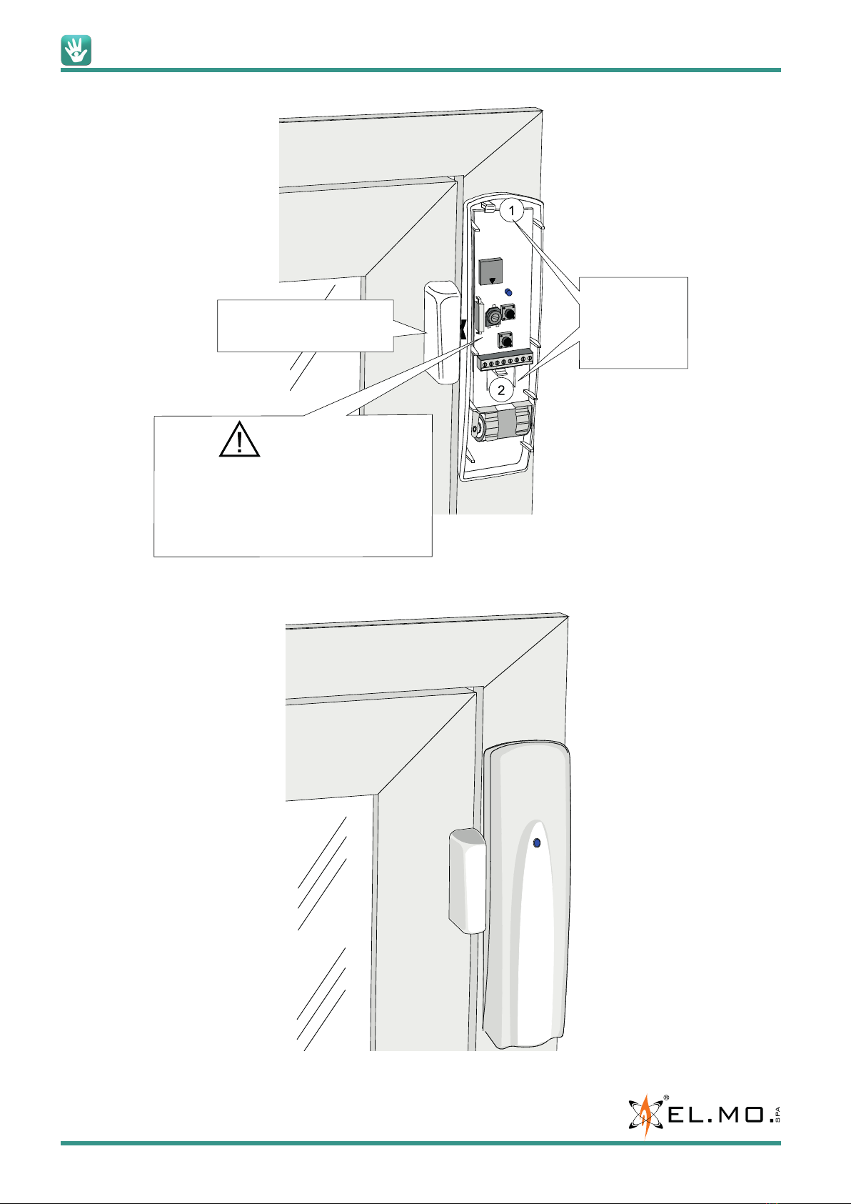
9. MOUNTING
Example of LUPUS2K transmitter mounting inside the housing of a
roll-up shutter. One of the possible fixing positions is indicated in the
picture on the right.
Search the best position in order to easily replace the battery when
needed: a possible position could be the external side of the box.
If you need an additional fixing support, avoid using a metal one in
order not to worsen the radio signal.
Note: the maximum distance from the roll-up shutter sensor can be
set via software to 1 or 8 meters: this is helpful in case of installation
with large windows, or in case you need to install the transmitter far
from the window.
Example of general mounting, phase 1.
HORIZONTAL
ADJUSTMENT
6.5 mm
MAX
NOMINAL
DISTANCE
5 mm
WARNING!
IN ORDER TO ACCESS THE UPPER FIXING
HOLE, PUSH OPEN THE PLASTIC CLIPS TO
UNHOOK THE ELECTRONIC BOARD AND
REMOVE IT.
FOR VOLANS2K, ALSO UNSCREW THE PIEZO
SENSOR WIRES FROM ITS TERMINAL BOARD.
TSV FIXING SCREWS
SUPPLIED WITH
WALL DOWELS
ALIGN THE REFERENCE ON
THE MAGNET BASE WITH
THAT ON THE SIDE OF
THE TRANSMITTER
LUPUS2K - VOLANS2K - TECHNICAL MANUAL - 090001113
elmospa.com
10
Example of general mounting, phase 2.
Example of general mounting, phase 3.
INSERT AND BLOCK THE CAP
WITH THE MAGNET.
HOOK THE BOARD
IN TO THE TWO
INDICATED CLIPS,
FOLLOWING
THE NUMBERING.
WARNING!
DURING THE INSTALLATION OF THE VOLANS2K
SENSOR, IT IS CONVENIENT TO REMOVE THE
BOARD.
AFTER CORRECTLY POSITIONING THE DEVICE,
CONNECT THE WIRES OF THE PIEZO SENSOR
(LOCATED ON THE BASE) TO ITS TERMINAL BOARD.

090001113 - TECHNICAL MANUAL - LUPUS2K - VOLANS2K
elmospa.com
11
9.1 Protection against removal from mounting surface
Compliance with EN 50131 regulation grade 2 requires that the device is protected against removal from the mounting
surface.
Install KSAS1013 kit (green) before fixing the detector base to the fixture.
A
- open pre-drilled area A
- cut the cable connector off
- feed the cable (from the free end) in the drilled hole
-
1 cm
fix a S4 dowel (supplied) to the wall at a height of 1 cm from the hole
- fix the eyelet to the dowel
- fix the detector base to the fixture
- connect the wires to the 24H terminals on board
LUPUS2K - VOLANS2K - TECHNICAL MANUAL - 090001113
elmospa.com
12
10. ELECTRICAL CONNECTIONS
10.1 Board general view
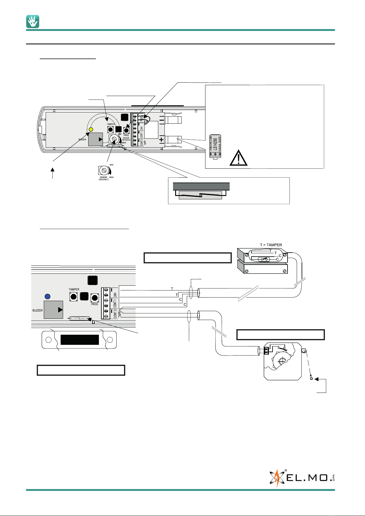
10.2 LUPUS2K general connections
Note: in order to ensure the product certification, it is necessary to connect the Tamper protection lines of the external
magnetic contact and of the roll-up sensor to the “24H” terminal.
USE THIS BUTTON AS
SPECIFIED IN THE CODE
ACQUISITION SECTION
TAMPER BUTTON FOR
PROTECTION AGAINST
HOUSING OPENING
EVENT DETECTION
INDICATOR
TX LED
IMPACT SENSITIVITY TUNING
ONLY FOR VOLANS2K MOD.
(THE PIEZO SENSOR IS LOCATED
ON BOARD BOTTOM)
SMD VIAL WITH MAGNETIC
CONTACT, NEXT TO THE
LED INDICATOR
THE PRODUCT IS PROVIDED WITH THE
BATTERY AS STANDARD EQUIPMENT.
AFTER INSTALLING THE PRODUCT, INSERT THE
BATTERY BETWEEN THE INDICATED TABS
RESPECTING THE POLARITY.
DO NOT TOUCH THE BATTERY TERMINALS
WITH YOUR FINGERS IN THIS PHASE.
1/2AA LITHIUM BATTERY MOD. ER14250 OR
EQUIV. REPLACE IT ONLY WITH A NEW
BATTERY OF THE SAME TYPE.
DO NOT REVERSE POLARITIES.
PAY ATTENTION NOT TO CAUSE
SHORT CIRCUITS.
DANGER EXPLOSION.
PIEZO SENSOR, RELATED TERMINAL
AND WIRING (ONLY FOR VOLANS2K)
ALL INPUTS CAN BE ENABLED AND
CONFIGURED VIA SOFTWARE
APPLICATION
ATTACH THIS TERMINAL TO THE LAST LAG WHEN
THE ROLL-UP SHUTTER LEANS ON THE WINDOW
MARBLE PLAN, EXTRACTING ALL THE THREAD AVAILABLE.
MAX LENGTH: 20 m
MAX LENGTH: 1 m
(DEFAULT)
OR 8 m
CONFIGURABLE
VIA SOFTWARE
ON-BOARD REED
CONTACT
MAGNET PROVIDED AS STANDARD EQUIPMENT.
INSTALL IT ON THE SIDE THAT HAS NO LABEL.
See Channel 1 software settings
See Channel 3 software settings
See Channel 2 software settings

090001113 - TECHNICAL MANUAL - LUPUS2K - VOLANS2K
elmospa.com
13
10.3 Allowed wiring types for LUPUS2K model
Using the software application, you can fully configure wiring types in order to optimize the device operations for the
required functions. The following screen is displayed in the “Zones” page, “Radio devices NG-TRX” tab corresponding
to the selected zone. For this zone, the specific model and information concerning the type of alarm generated and the
firmware version are displayed.
The “Enable Led” selection allows you to enable/disable the on-board LED according to the operational necessities.
Flag the “Buzzer activation functions” checkbox to apply to the specific channel the functional settings concerning the
internal buzzer that have been configured in the “Buzzer activation” selection displayed in the “Options NG-TRX” area.
During the detector learning phase, the channels are assigned to three consecutive zones; however, you can immediately
avoid memorizing an unused channel or you can disconnect such a channel from the browser application in order to
occupy less zones.
The software menu can also be used to move the channels to different zones, e.g. to group all roll-up shutter sensors on
consecutive zones. Click on the triangle located at the right of the zone number and choose a different zone from the list,
then click on the “Jump” button in order to move the channel (and the zone name) to the selected zone.
In case the zone is already occupied by other devices, the software application will signal the code conflict.
You can configure the type for channels 2 and 3 independently, choosing between magnetic and roll-up shutter type. For
the latter, you can define the wiring length (“Fast”: 1 m, “Fast 8 metres”: 8 m), the number of pulses and the timeout for
the detection of a valid alarm.
Timeout (s) = 5, 10, 15 (default) , 20.
Number of pulses = 1, 2, 4 (default), 8.
After configuring the settings, write the configuration to the control unit and then perform the functional test.
Note: use the “Fast 8 metres” option only if necessary: it may affect battery life.
LUPUS2K - VOLANS2K - TECHNICAL MANUAL - 090001113
elmospa.com
14
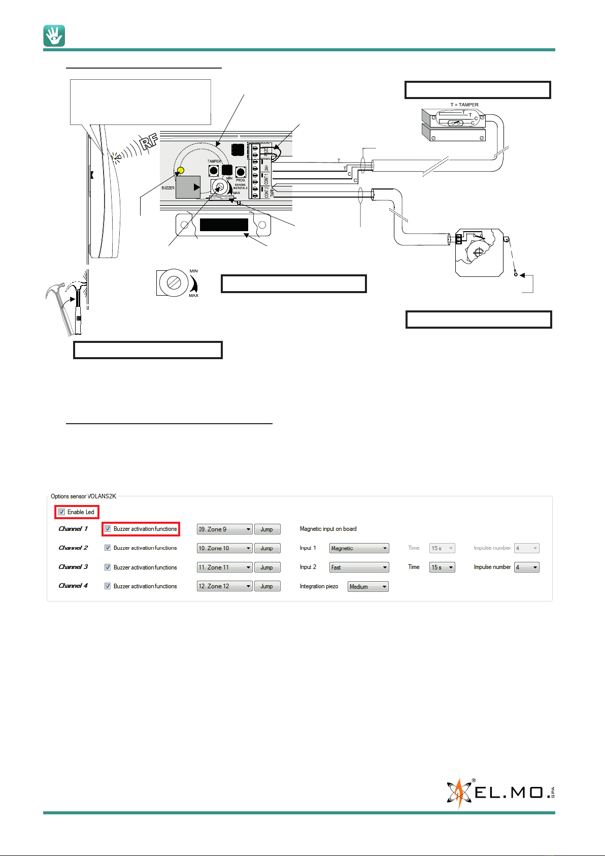
10.4 VOLANS2K general connections
Note: in order to ensure the product certification, it is necessary to connect the Tamper protection lines of the external
magnetic contact and of the roll-up sensor to the transmitter “24H” terminal.
10.5 Allowed wiring types for VOLANS2K model
Using the software application, you can fully configure wiring types in order to optimize the device operation in the required
functions. The following screen is displayed in the “Radio devices NG-TRX” tab corresponding to the selected zone. For
this zone, the specific model and other informations concerning the type of alarm generated and the firmware version are
displayed.
The “Enable Led” selection allows to enable/disable the on-board LED according to the operational necessities.
The “Walk Test” and “Learning” phase indications will be visualized even when the LED is not enabled.
Checking the “Buzzer activation functions” allows to apply to the specific channel the functional settings of the internal
buzzer that have been configured in the “Buzzer activation” selection displayed in the “Options NG-TRX” tab right above
this one.
During the detector learning phase, the channels are assigned to four consecutive zones; however, you can immediately
avoid memorizing an unused channel or you can disconnect such a channel from the browser application in order to
occupy less zones.
The software menu can also be used to move the channels to different zones, e.g. to group all roll-up shutter sensors on
consecutive zones. Click on the triangle located at the right of the zone number and choose a different zone from the list,
then click on the “Jump” button in order to move the channel (and the zone name) to the selected zone.
In case the zone is already occupied by other devices, the software application will signal the code conflict.
PIEZO SENSOR POSITION.
WARNING:
TO GET THE HIGHEST SENSITIVITY, SET THE
HOUSING BOTTOM PERFECTLY IN CONTACT
WITH THE SURFACE TO BE PROTECTED
THE PIEZO SENSOR IS LOCATED IN THIS POSITION
ON THE BOARD BOTTOM
ALL INPUTS CAN BE ENABLED AND
CONFIGURED VIA SOFTWARE APPLICATION
ATTACH THIS TERMINAL TO THE LAST LAG WHEN
THE ROLL-UP SHUTTER LEANS ON
THE WINDOW MARBLE PLAN, EXTRACTING ALL
THE THREAD AVAILABLE.
MAGNET PROVIDED AS
STANDARD EQUIPMENT.
INSTALL IT ON THE SIDE
THAT HAS NO LABEL.
ON-BOARD
REED
CONTACT
THREE LEVELS OF INTEGRATION CAN BE SET VIA SOFTWARE
APPLICATION: MEDIUM (DEFAULT), LOW AND HIGH
IMPACT SENSITIVITY TUNING
(THE PIEZO SENSOR IS LOCATED
ON BOARD BOTTOM)
LED FOR
OPERATION
AND IMPACT
INDICATION
PIEZO SENSOR WIRES.
CONNECT THEM TO THE
“PIEZO” TERMINALS.
MAX LENGTH: 20 m.
MAX LENGTH: 1 m
(DEFAULT),
OR 8 m
CONFIGURABLE
VIA SOFTWARE.
See Channel 1 software settings
See Channel 3 software settings
See Channel 2 software settings
See Channel 4 software settings
090001113 - TECHNICAL MANUAL - LUPUS2K - VOLANS2K
elmospa.com
15
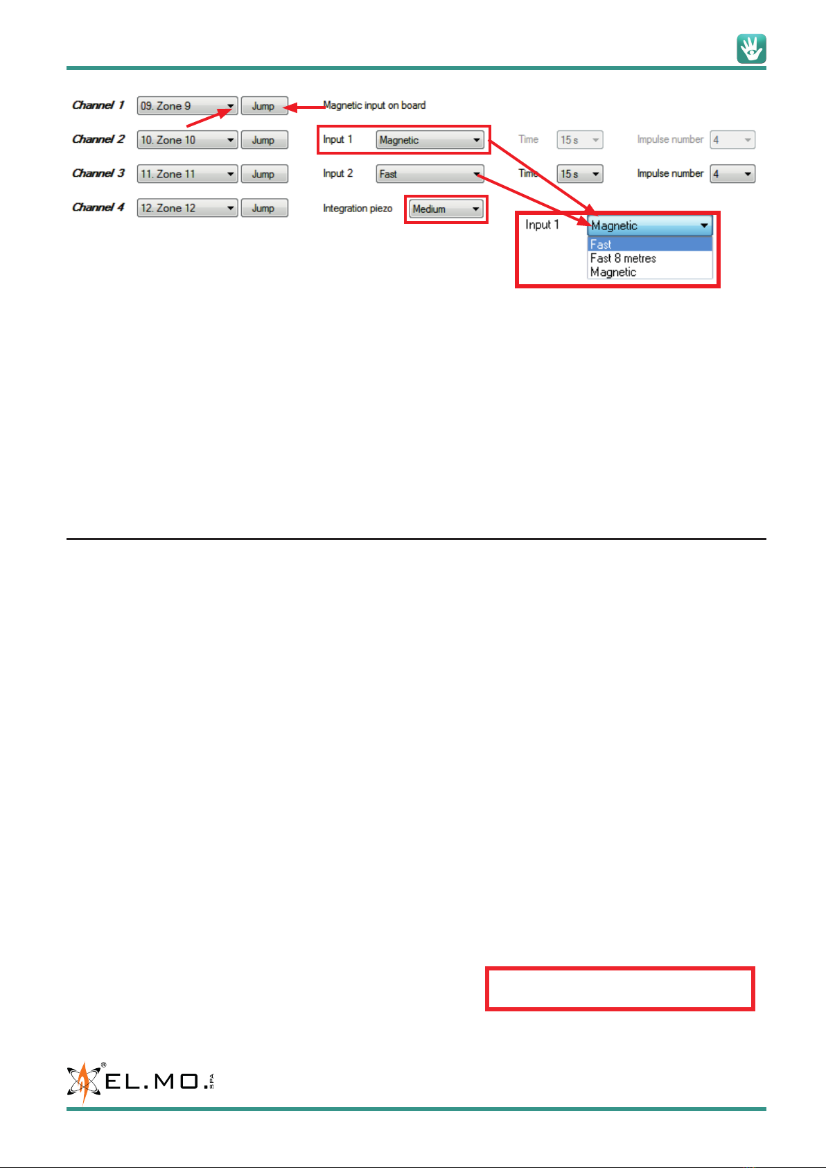
You can configure the type for channels 2 and 3 independently, choosing between magnetic and roll-up shutter type. For
the latter, you can define the wiring length (“Fast”: 1 m, “Fast 8 metres”: 8 m), the number of pulses and the timeout for
the detection of a valid alarm.
Timeout (s) = 5, 10, 15 (default) , 20.
Number of pulses = 1, 2, 4 (default), 8.
Note: use the “Fast 8 metres” option only if necessary: it may affect battery life.
The built-in inertial sensor response can be adjusted based on the material and the fixing position; the sensitivity can be
adjusted using the trimmer indicated in the electrical connection picture; the pulse integration can be set via software
application, choosing among 3 levels: Medium (default), Low, High. The picture refers to default settings.
After configuring the settings, write the configuration in the control unit and then perform the functional test.
11. CODE MEMORIZATION
Note: during the code acquisition phases, keep in mind that the control unit identifies LUPUS2K and VOLANS2K as multi-
channel devices.
The following procedure allows to memorize the transmitter to a Villeggio NG-TRX control unit.
1. Power up the transmitter by inserting the battery. Respect the polarity as indicated in the printed board and in this
manual.
2. Enter the programming menu by typing the installer code on a system keypad.
3. Press “OK”, then use the arrow buttons to browse to “Learn radio det.”.
4. Press “OK”, then either use the arrow buttons to browse through the available zones or type a zone address.
5. Press “OK”, then press 1 to store the code to the control unit. Press “OK” again.
6. Immediately press the “PROG” button of the transmitter (next to the magnet), and keep it pressed for at least 3 seconds.
7. A double beep of the internal buzzer and a double blink of the transmitter LED signal a successful memorization.
8. The control unit also beeps twice to confirm the successful memorization.
9. The display shows the channels identified by the control unit in this sequence:
CH1 with Alarm/Reset, referring to the built-in magnetic contact,
CH2 with Alarm/Reset, referring to the magnetic contact to be wired,
CH3 with Alarm event, referring to the roll-up shutter detector to be wired,
CH4 with Alarm event, referring to the built-in piezo sensor (available only for the VOLANS2K model).
For each channel, press “OK” for confirmation or # to switch to the next channel, up to the last available channel.
Note: during the acquisition phase, you can choose between the acquisition of either all or only some of the channels.
After a “partial” acquisition, the channels cannot be added to the control unit manually, but only using BrowserOne.
10. If the memorization fails, the internal buzzer plays a long, deep beep. Restart from point 6.
11. Exit the programming menu, pressing “OK” any time you are asked to save/memorize the new settings.
12. Use BrowserOne with the module for your NG-TRX control unit to read the configuration, change the settings for the
transmitter, then write the modified configuration. See the next chapter.
13. The new settings will be operative from after the next transmission.
14. Open and close the window or the roll-up shutter (or generate an
inertial alarm in case you are using the VOLANS2K detector) to test
that the transmitter is working. Since the internal buzzer is usually disabled (unless you activated it via browser in
order to ease the test), the only indication is given by the LED turning on.
Note: The device will not be memorized in
case of low battery.

LUPUS2K - VOLANS2K - TECHNICAL MANUAL - 090001113
elmospa.com
16
12. TRANSMITTER CONFIGURATION VIA SOFTWARE
The transmitter can be fully programmed by using BrowserOne v. 3.4.7 or higher with the module for the control unit v.
8.4.11 or higher. The control unit firmware must be 8.2.0.0 or higher.
See the specific technical documentation for information on other expressly compatible control unit models.
Perform the following operations:
• Start the connection as explained in the programming manual of the control unit.
• Read the current configuration, open the “Zones” page and identify the number of the zone that is assigned the
acquired code of the transmitter.
• Still in the Zones page, open the “Radio devices NG-TRX” tab.
On the side of the page concerning the NG-TRX wireless devices, some useful notes are displayed for the correct
configuration of the detector, depending on the selection of the “Supervision interval” and the “Tx Boost” function.
In the bottom page you can find the specific section for the transmitter channels configuration, described in chapter “10.
ELECTRICAL CONNECTIONS”.
Event type for each channel.
Press to delete the acquired code.
The picture highlights the
informations concerning the
radio NG-TRX system, the
firmware version and the
transmitter model.
Activates the internal buzzer of the transmitter in
alarm or reset for a local operation check of all
channels (unless differently set for each single
channel). Default: disabled (any anomaly is
signalled in any case).
Function available only if you set a precise
supervision interval; it allows you to delay the
anomaly signal generated by the “supervision
failure” signal.
Select to increase the power of the RF section.
WARNING: this causes a decrease in battery duration. Use only when the range is not
sufficient.
You can choose between “Automatic”, “Minimum
consumption” to maximize battery life when the
signal reception is sufficient, “Maximum power”
in case of high limitations due to adverse site
conditions (drawback: battery life reduction).
Default: Automatic.
Set the periodic transmission cadence necessary
for the control unit to detect the transmitter control
failure, with the consequent reporting and alert
actions settable from other software pages.
Setting a short interval will affect the battery
duration of the device. In the Default condition, the
general parameters will be used: they are set in the
“System options” page for the NG-TRX devices.
These two lines are
actually only one, whose
content changes.
Example

090001113 - TECHNICAL MANUAL - LUPUS2K - VOLANS2K
elmospa.com
17
Open the “System options” page, “Options NG-TRX” tab, where the general options of the NG-TRX devices are available.
Here you can select the settings that also involve the LUPUS2K and VOLANS2K transmitters.
The listed options are valid for all NG-TRX devices, except remote controls:
1. Delay supervision anomaly: NG-TRX devices generate the supervision failure event 6 supervision cycles later.
Example: if the default supervision timer is set to 240 minutes and the delay function is active, the supervision
anomaly is generated 24 hours later (240 minutes × 6).
2. Delay low battery signalling: if active, the devices run more thorough controls before sending the low battery signal.
3. Enable detection RF interference: this selection allows to detect interferences in the three 868 MHz channels and
to generate the event log. The interference detection on the preferred channel involves the transition to an other
channel if the same interference has already been detected and logged in the last 48 hours.
The general options selection about the 434 MHz interference detection does not concern NG-TRX devices.
4. RF Interference as Tamper: select this function to use an RF interference event to generate a tampering event, along
with the resulting management.
Selection of the multi-channel reception (3 channels), also involving the default/preferential channel selection and
the transmission strategy. In case the function is active but communication with the control unit is not possible, the
device will use one of the other two remaining channels. For more details see “13.4 Multi-channel reception and
strategy”.
The default channel shall be set by the installer, otherwise it is Ch1.
Note: the system uses the preferred channel based on the interference level; if there is no interference, the default
channel is used. Each channel change will be recorded in the event log.
Common supervision for all system devices,
except remote controls; if necessary, it can be
modified for each device.
1
2
3
4

LUPUS2K - VOLANS2K - TECHNICAL MANUAL - 090001113
elmospa.com
18
13. OPERATING MODES
13.1 Walk test - System test
The Walk test condition can be activated via keypad, from the SYSTEM TEST » ZONE TEST menu.
The beginning of the operating mode is indicated by three beeps of the internal buzzer and by the LED blinking.
After exiting the Walk test mode, the internal buzzer will enter operating mode, whose configuration depends on browser
programming.
13.2 Operation
In operative conditions, the detector only uses the cover LED, for both alarm or tamper conditions. These conditions can
also be indicated by the internal buzzer if it has been programmed for alarm or for alarm and reset. The buzzer is disabled
by default.
13.3 Supervision
In case you have made some changes in supervision times (with subsequent memorization in control unit), they will be
updated to the set values upon the first transmission. Therefore, if some devices are temporarily not powered, the control
unit will signal them considering a different supervision time than the one just set.
After the next power-on of the devices, the supervision time will be updated to the set value. In case of subsequent detector
power failure, the system will keep the current supervision time.
In case you change the supervision time after a control unit reset, it will be updated at the first transmission.
Namely, immediately after the main reset, the supervision time that will be considered is the current one; any devices that
are not aligned within that time will enter the missed supervision state.
13.4 Multi-channel reception and strategy
It can be set in the NG-TRX Options page.
If the function is ACTIVE (default), the control unit is able to receive on all channels; if it is not active, the control unit
receives on one channel at a time. It is possible to increase reliability, when there are interferences on a specific channel,
by turning off the multi-channel reception.
Note: We suggest that you disable the Multi-channel reception when you are aware of the existence of radio interference
on one or more channels. In this case the control unit will receive only on the default/preferential channel, although the
detector performs transmission attempts on all channels.
13.5 Default/preferential channel
Default channel
In case of radio interferences, it is recommended to set the most free channel as the default channel (you can check it
through the monitoring functions on the browser and control unit).
In case of strong interferences, it is possible to increase the reliability of the communication by disabling the multi-channel
reception.
Preferential channel
The variation of the preferential channel is performed in case of interference detection. The control unit can change the
preferential channel independently of the activation of multi-channel reception mode.

090001113 - TECHNICAL MANUAL - LUPUS2K - VOLANS2K
elmospa.com
19
14. BATTERY REPLACEMENT AND DISPOSAL
The LUPUS2K and VOLANS2K detectors use a Lithium 3.6 V 1.2 Ah battery mod. ER14250 or LS1425 (1/2AA). Replace
this battery only with a new one of the same model. Observe the following insertion instructions:
1. Remove the low battery.
2. Press and release 3-4 times the Tamper button to discharge any charged capacitors.
3. Check the distance of the battery clip tabs. In idle conditions, they have to take an inclination similar to that shown in
the figure. The distance between the two tabs should be about 25 mm; if more, you will have to push them inward to
obtain the indicated distance.
The correct position of the tabs allows an excellent electrical contact and avoids possible and erroneous signalling of
low battery.
4. Insert the new battery. Check the polarity.
5. Reset any low battery memories in control unit or in the compatible receiving device.
Dispose of the old battery in full compliance with the current regulations, using the appropriate containers.
The materials used are highly polluting and harmful if released to the environment.
25 mm

LUPUS2K - VOLANS2K - Radio transmitters for wireless NG-TRX intrusion detection systems
TECHNICAL MANUAL - August 2018 edition 090001113
The information and product features herein are not binding and may be changed without prior notice.
EL.MO. SpA Via Pontarola, 70 - 35011 Campodarsego (PD) - Italy
Tel. +390499203333 - Fax +390499200306 - Technical Ass. +390499200426 - www.elmospa.com - inter[email protected]
15. TABLE OF CONTENTS
1. GENERALS .................................................................................. 3
2. FEATURES................................................................................... 3
3. MECHANICAL FEATURES ...................................................................... 5
4. HOW TO DISTINGUISH THE DEVICES ............................................................ 5
5. HOUSING OPENING AND CLOSING . . . . . . . . . . . . . . . . . . . . . . . . . . . . . . . . . . . . . . . . . . . . . . . . . . . . . . . . . . . . . . 6
6. FIRST POWER-ON OR BATTERY REPLACEMENT . . . . . . . . . . . . . . . . . . . . . . . . . . . . . . . . . . . . . . . . . . . . . . . . . . . 6
7. INSTALLATION ............................................................................... 7
8. COVERAGE AND SENSITIVITY................................................................... 8
9. MOUNTING .................................................................................. 9
9.1 Protection against removal from mounting surface.............................................11
10. ELECTRICAL CONNECTIONS ..................................................................12
10.1 Board general view .....................................................................12
10.2 LUPUS2K general connections ............................................................12
10.3 Allowed wiring types for LUPUS2K model ...................................................13
10.4 VOLANS2K general connections...........................................................14
10.5 Allowed wiring types for VOLANS2K model ..................................................14
11. CODE MEMORIZATION .......................................................................15
12. TRANSMITTER CONFIGURATION VIA SOFTWARE .................................................16
13. OPERATING MODES..........................................................................18
13.1 Walk test - System test...................................................................18
13.2 Operation .............................................................................18
13.3 Supervision............................................................................18
13.4 Multi-channel reception and strategy .......................................................18
13.5 Default/preferential channel ..............................................................18
14. BATTERY REPLACEMENT AND DISPOSAL .......................................................19
15. REQUIREMENTS FOR COMPLIANCE TO THE EN50131 STANDARD ...................................19
16. TABLE OF CONTENTS ........................................................................20
This manual suits for next models
1
Table of contents


