Online 600 Series User manual

ONLINE ELECTRONICS LTD
600_5001_A01 Page 1 of 12
Online Electronics Ltd
Online House
Blackburn Business Park
Woodburn Road, Blackburn
Aberdeen
AB21 0PS
UK
+44 (0)1224 714 714
www.online-electronics.com
600 SERIES ACOUSTIC PINGER
OPERATING MANUAL
The 600 Series Pingers are high specification pingers used for
pig tracking and other subsea marking and location functions,
Intended for use in pipeline diameters of 6” to 8”

ONLINE ELECTRONICS LTD
600_5001_A01 Page 2 of 12
CONFIGURATION INFORMATION
MODEL:
SERIAL NUMBER:
FREQUENCY:
ACOUSTIC POWER
PULSE LENGTH:
CELL TYPE:
NUMBER OF CELLS:
PING RATE 1:
RATE 1 BATTERY LIFE AT +5°C:
PING RATE 2:
RATE 2 BATTERY LIFE AT +5°C:
DELAYED START TIME (DD:HH:MM):
: :

ONLINE ELECTRONICS LTD
600_5001_A01 Page 3 of 12
600_5001 600 SERIES ACOUSTIC PINGER MANUAL
Checked
(IF APPLICABLE)
Date
(IF APPLICABLE)
Approved
Date
Rev
Date
By
Summary of change
A00
01/08/17
BG
CR00485: Was 600 Series Pinger Manual RevA10. CR00380 Address
change. CR00499 Front Cover update.
A01
03/10/17
BG
Cover page updates
COMMENTS:
ca , 08:45:09, 05/10/2017

ONLINE ELECTRONICS LTD
600_5001_A01 Page 4 of 12
CONTENTS Page
1. GENERAL DESCRIPTION ......................................................................................... 5
2. SPECIFICATIONS ................................................................................................... 6
3. RULES FOR SAFE OPERATION ................................................................................. 7
4. OPERATION .......................................................................................................... 8
4.1. FUNCTION TEST ................................................................................................ 8
4.2. INSTALLATION .................................................................................................. 8
4.3. DEPLOYMENT .................................................................................................... 9
4.4. BATTERY REPLACEMENT ..................................................................................... 9
4.5. DUAL RATE ..................................................................................................... 10
4.6. GRID.............................................................................................................. 10
4.7. DELAYED START .............................................................................................. 10
5. MAINTENANCE .................................................................................................... 11
5.1. O-RING REPLACEMENT..................................................................................... 11
5.2. ROUTINE MAINTENANCE AND STORAGE ............................................................. 11
6. WARRANTY ......................................................................................................... 11
7. DISPOSAL OF UNIT.............................................................................................. 12

ONLINE ELECTRONICS LTD
600_5001_A01 Page 5 of 12
1. GENERAL DESCRIPTION
The 600 Series Pingers are high specification, microprocessor controlled acoustic transmitters
developed for use as advanced PIG transmitters and for other subsea marking and location
functions.
A 600 Series Pinger may be fitted to a PIG for use in offshore, fluid filled pipelines. The
acoustic signal generated by the pinger is exceptionally powerful and stable and allows the
approximate PIG location to be established from the surface using an acoustic receiver and
hydrophone (e.g. OEL 2001). The exact location can then be determined using a directional
receiver such as the diver operated OEL PR1, or ROV mounted OEL 2001RS/2401 system.
The 600 Series Pingers are highly configurable and their performance and functionality can be
tailored to meet specific customer requirements. For example, if two pingers are required to
operate in close proximity to one another, different frequencies and/or ping rates can be
configured during manufacture to allow for differentiation between their transmissions.
The 600 Series Pingers are capable of sending acoustic transmissions up to 2km, although the
effective range is dependent upon the specific configuration, mounting arrangement, and
environmental conditions.
The standard 600 Series model (shown in the figure above) is powered by 3 Alkaline C Cells
and produces up to 10W of acoustic power at a single operating frequency in the range of 26-
42kHz (configured at time of manufacture). In addition to the standard model a number of
alternative configurations are available that offer additional functionality and/or performance:
EXTENDED HOUSING OPTION: Extended housings are available that increase the battery
capacity from 3 to 4 cells. These configurations have an increased length of 317mm and an
increased weight in air of 1.35kg.
SHORTENED HOUSING OPTION: Shortened housings are available that decrease the overall
length to 217mm and decrease the overall weight to 0.85kg. The short version accommodates
two C cells.
LITHIUM CELLS OPTION: Lithium C cells may be fitted in place of the standard alkaline C
cells and will significantly increase the battery life of the unit (short and standard housing
configurations only).
DUAL RATE OPTION: 600 Series Pingers with the Dual Rate option incorporate an external
connector cable that allows them to be interfaced with an external piece of equipment for use
as a long range, remote alarm. For example, a 600 Series Pinger with the dual rate option
may be interfaced with an OEL Smart Gauge Plate and used to send an alert if the gauge plate
is triggered.
GRID™OPTION: Has the same functionality as the Dual Rate option above, except that the
unit also transmits the time of a BWGP event as a series of acoustic pulses. This allows the
location where the event occurred to be determined without having to recover the pinger first.

ONLINE ELECTRONICS LTD
600_5001_A01 Page 6 of 12
DELAYED START OPTION: In order to conserve battery life, the unit can be configured to
enter a very low power mode for a pre-configured duration before it starts pinging.
2. SPECIFICATIONS
REFER TO THE FRONT COVER OF THIS MANUAL FOR THE SPECIFIC CONFIGURATION
OF THE PINGER ACCOMPANYING THIS MANUAL.
GENERAL:
Battery Life at +5°C from 3x Duracell ID1400 Alkaline C Cells ......... 16.5 Days (2s Ping Rate)*
Battery Life at +5°C from 3x SAFT LS26500 Lithium C Cells ............... 26 Days (2s Ping Rate)*
Acoustic Output Power ...................................................................................... 10W ±3dB
Range ..........Up to 2km (Dependent on configuration, mounting and environmental conditions)
Beam Pattern.................................................................................. Omni-directional ±3dB
Operating Frequency.......................................................... Pre-Configured within 26-42 kHz
Pulse Length ............................... 5ms ±5% as standard (Configurable between 1 and 30 ms)
Ping Rate............................................... From 1 ping per second, to 1 ping every 30 seconds
Operating Temperature Range ......................................................................-2°C to +54°C
External Pressure Rating .......................................................................... 3000m / 300bar
Weight in Air........................................................................................................... 1.1kg
MATERIALS:
Housing Material ............................................................................. 316 STAINLESS STEEL
Endcap Material..........................................................................................ALLOY BRONZE
Transducer Material ........................................................................................... PEEK / PU
O-Ring Material ..................................................................................................... NBR70
*ALTERNATIVE CONFIGURATIONS
The battery life of a 600 Series Pinger is dependent on the operating temperature, acoustic
power, ping rate, pulse length and the number and type of C Cells. The acoustic power, pulse
length and ping rate can be configured by OEL at the time of manufacture to match the
customer’s desired performance and battery life. Please contact OEL to discuss any specific
project requirements.

ONLINE ELECTRONICS LTD
600_5001_A01 Page 7 of 12
3. RULES FOR SAFE OPERATION
⚠WARNING: Any operation involving pressure is potentially hazardous. No person should
use this equipment unless fully aware of the potential hazards of working with pressurised
vessels. The purchaser of this equipment is responsible for the training and competence of
operators and the manner in which it is used. This manual should be read through and
understood before installation and commissioning so that the operator is familiar with the
equipment. Contact Online Electronics Ltd immediately should any difficulty arise in the use of
this equipment.
⚠WARNING: DO NOT open when an explosive atmosphere may be present. Always use
caution when opening equipment which has been in a pressurised environment. It is possible
for pressure to leak into the equipment and remain there even after external pressure has
been removed. ALWAYS point the end to be opened towards a safe area and away from
yourself or others. Contact Online Electronic immediately if there is a suspicion that the
equipment has become pressurised.
⚠WARNING: Replace all batteries at the same time. NEVER install used batteries. NEVER
install a mix of new and used batteries. USE ONLY new batteries from the same package or
manufacturing batch. DO NOT mix different brands or types of batteries. ALWAYS observe
correct battery polarity. New batteries should be installed before each deployment.
⚠WARNING: Do not expose to aggressive solvents or chemicals which could be harmful to
the HOUSING, O-RINGS, CONNECTORS or any other parts of the equipment.
⚠WARNING: Lithium cells have a very high energy density and can be dangerous if not used
or handled correctly. For a general guide on handling lithium cells, see address below:
http://www.saftbatteries.com/force_download/Selector_guide_Lithium_2015_LD_0.pdf
⚠CAUTION: Opening of the equipment should take place in a clean laboratory environment.
⚠CAUTION: To prevent the formation of condensation within the transmitter, allow the
transmitter temperature to stabilise within the laboratory environment for a minimum of 6
hours prior to opening.
⚠CAUTION: It is possible for liquids to become trapped in threads and/or gaps around
openings. ALWAYS point the end to be opened downwards to allow any trapped liquid to drain
out of and not into the equipment.
⚠CAUTION: All subsea connections must be terminated or blanked prior to deployment.

ONLINE ELECTRONICS LTD
600_5001_A01 Page 8 of 12
4. OPERATION
Familiarise yourself with all of the rules for the safe operation of this equipment as described in
Section 3 RULES FOR SAFE OPERATION.
4.1. FUNCTION TEST
An acoustic receiver system, such as the OEL 2001 Acoustic Receiver and hydrophone, is
required in order to function test a 600 Series Pinger.
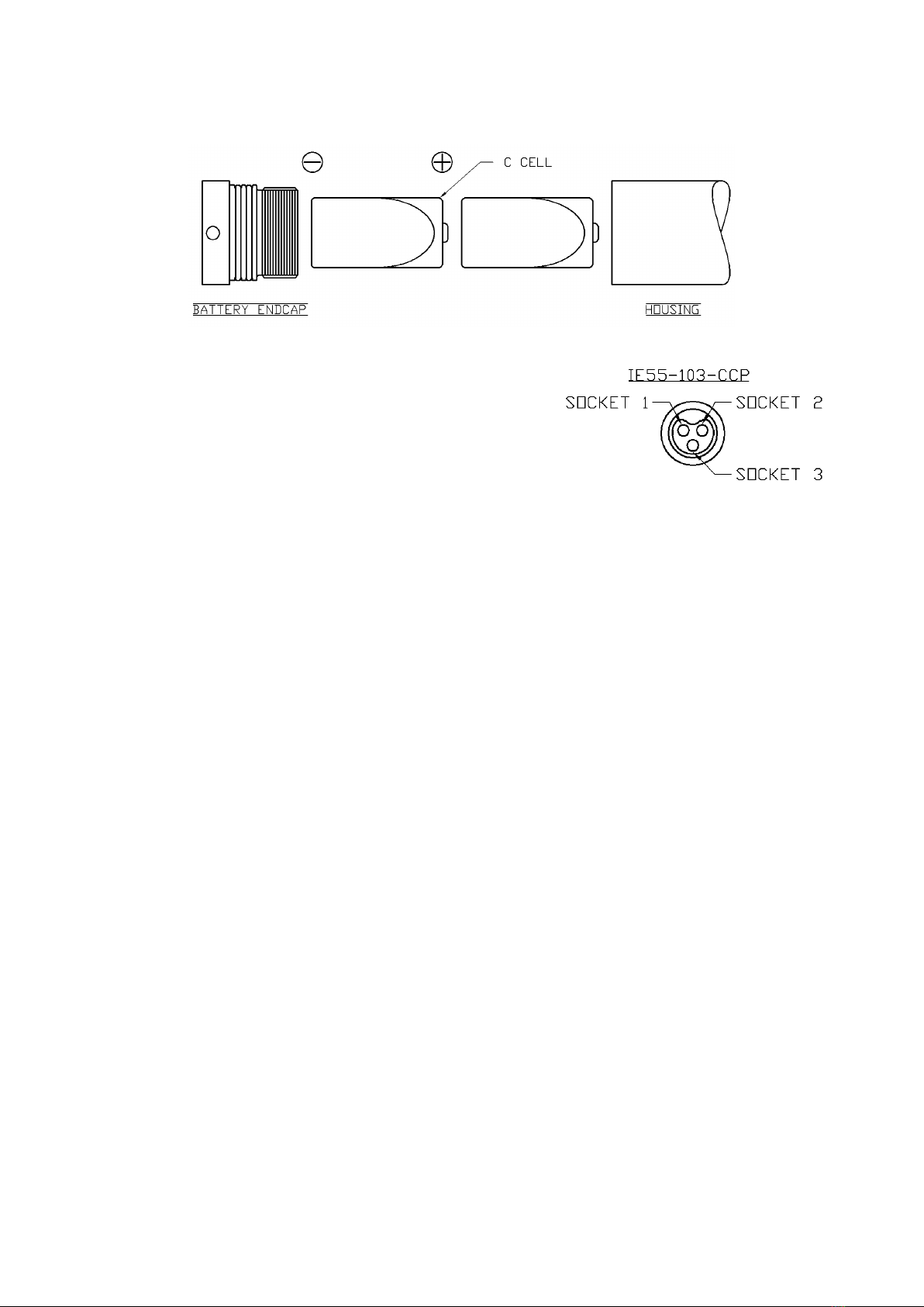
1. Ensure the battery end cap is tightened.
2. Activate the pinger by closing the saltwater links using the mechanical link provided, or by
simply bridging the links with bare fingers. NOTE: if using the mechanical link to bridge the
contacts, the heat shrink will need to be removed beforehand.
3. Set the frequency of the acoustic receiver system to match the frequency of the pinger
(refer to the label on the front of the unit for the configured frequency). Set the receiver
sensitivity to maximum and position the hydrophone approximately 30cm from the front of
the pinger (in air). With the pinger activated, confirm that transmitted signal is being
picked up by the acoustic receiver. If a 2001 acoustic receiver system is being used, the
received signal should be at approximately 50% of the maximum level.
4. Ensure that the acoustic pulses received by the acoustic receiver system match the
expected PING RATE of the pinger. Refer to Page 2 of this manual for the PING RATES of
the unit supplied.
5. If a pinger with the dual rate option is being tested, then either PING RATE 1 or PING
RATE 2 will be transmitted, depending on whether the DUAL RATE contact is open or
grounded. Refer to Section 4.5 DUAL RATE for further information. If the wrong ping rate
is being transmitted, this would suggest that the external equipment is either damaged or
not connected properly. If this happens, contact OEL for advice before initiating any
investigation process.
DISCLAIMER –Any investigation without taking advice could potentially damage the
pinger/external equipment.
6. Providing the PING RATES and SIGNAL LEVEL are correct, the system operation has been
verified and the function test is complete.
4.2. INSTALLATION
The PINGER TRANSDUCER must be left protruding from the PIG body in order to minimise
attenuation of the acoustic transmission.
1. Ensure the BATTERY ENDCAP is fully tightened.
2. Place the pinger within the cavity of the PIG, ensuring that it is secure and cannot move
around.
3. Wedging blocks of PU should be used as required to reduce any movement or vibration of
the pinger within the pig. NOTE: The wedging blocks should be in contact with the pinger
body only, not with the transducer.
4. The transducer head must be protected against physical impact.
5. If the mechanical link is not going to be used, ensure that there is adequate access for
water to flood the saltwater links.

ONLINE ELECTRONICS LTD
600_5001_A01 Page 9 of 12
6. If the pinger is fitted with an external connector then the connector MUST be terminated
or blanked.
4.3. DEPLOYMENT
1. At least 24 hours prior to deployment, any personnel who are to be involved in the
operation of the pinger should review this entire manual and be given time to practice
operating the pinger and receiver system. By familiarising themselves with the system
operation prior to deployment, the chances of a potentially costly operator error are
greatly reduced.
2. Refer to Page 2 of this manual for the expected battery lifetime and ensure it is adequate
for the planned duration of operations.
3. Fresh batteries are installed at OEL prior to shipping, however if the unit has been
deployed previously, the batteries should be replaced as detailed in Section 4.4 prior to
deployment.
4. Ensure that the battery endcap is tightened.
5. If the pinger is fitted with an external connector then it must be terminated or blanked.
6. It is recommended that the pinger is activated by bridging the saltwater links with the
mechanical link provided, however the pinger will also activate if the saltwater contacts
are flooded with a conducting fluid such as salt water, fresh water or MEG. If using the
mechanical link to bridge the contacts, the heat shrink will need to be removed
beforehand.
7. Perform a FUNCTION TEST as described in Section 4. Providing the function test has been
completed successfully, deployment can proceed.
4.4. BATTERY REPLACEMENT
1. Familiarise yourself with the NOTES given at the start of Section 3 RULES FOR SAFE
OPERATION.
2. Remove the BATTERY ENDCAP slowly to relieve any internal pressure.
3. Remove all C Cells. Visually inspect the batteries, contact Online Electronics immediately if
there are any signs of damage or electrolyte leakage. Dispose of the old batteries in a
responsible way.
4. Observing the battery polarity shown in the figure below, insert the new C Cells into the
battery compartment, POSITIVE END first. Note that the unit is programmed with a set
battery configuration so that it will stop pinging when the supply voltage drops below a
threshold level. Since the threshold level is dependent on the cell configuration, the
replacement cells must be of the same type as the original cells.
5. Once all batteries are installed, ensure that it is the FLAT, NEGATIVE END of the batteries
which you see when looking into the open end of the unit.
6. Examine the O-ring seals for any signs of contamination or damage, replace and/or re-
grease if necessary.
7. Ensure all the O-rings are located correctly and then refit the BATTERY ENDCAP.

ONLINE ELECTRONICS LTD
600_5001_A01 Page 10 of 12
8. Perform a FUNCTION TEST as described in Section 4 to confirm that the unit is functioning
as expected.
4.5. DUAL RATE
600 Series Pingers with the DUAL RATE option are
configured with two different ping rates and are typically
fitted with an IE55(W)-10-CCP 3-Way subsea connector
with the tail moulded into the transducer. Socket 1 is the
GND connection, Socket 2 is the DUAL RATE Rate/RX
connection and Socket 3 is the TX connection.
When the pinger is active and the DUAL RATE contact is shorted to the GND connection, the
pinger will transmit at Ping Rate 1 (the Pass Ping Rate or PPR).
When the pinger is active and the DUAL RATE contact is open (resistance to GND > 3k), the
pinger will transmit at Ping Rate 2 the (the Fail Ping Rate or FPR).
The contacts are usually controlled by an external piece of equipment, such as an OEL 7001
BWGP, but may also be opened or closed mechanically. Refer to Page 2 of this manual for the
ping rates of the unit supplied with this manual.
4.6. GRID
Like the DUAL RATE units, units with GRID™(GAUGING RUN INTEGRITY DATA) functionality
are typically fitted an IE55(W)-10-CCP 3-Way subsea connector tail moulded into the
transducer. The functionality of the GRID™units is similar those with DUAL RATE except that
the unit also logs the time of a gauge plate event and then transmits it at set intervals as a
series of acoustic pulses. These pulses can then be decoded in order to determine the location
at which the gauge plate occurred without the need to recover the pig first. Interfacing the
unit with an ARGF ring, in addition to the standard BWGP allows the unit to log multiple
pipeline events. The connections are the same as for the DUAL RATE above but with Socket 2
as the BWGP/RX connection and Socket 3 as the TX/ARGF connection. Please see the separate
GRID™Manual for a full explanation of the GRID™system functionality.
4.7. DELAYED START
Upon activation, a unit with DELAYED START functionality enters into a low powered “sleep
mode”for a pre-configured amount of time in order to conserve battery life. Once the
programmed delay has elapsed, the unit will start pinging as per a standard 600 series unit.
In order to confirm that the unit is operating correctly, the unit transmits at the standard pulse
rate for 55 seconds, pauses for 5 seconds and then transmits the pre-programmed DELAYED
START TIME as a coded series of pulses (see GRID™ Manual for instructions on how to decode
the signal). The unit will then transmit at the standard rate for a further minute before

ONLINE ELECTRONICS LTD
600_5001_A01 Page 11 of 12
entering the low powered “sleep mode”. The unit will remain in the low power mode until the
delay time has elapsed.
This initial behavior allows the user to confirm that the unit has been activated, is pulsing at
the correct pulse rate (which also verifies the DR/GRID connection) and that the delayed start
time for the operation is correct.
5. MAINTENANCE
Familiarise yourself with all of the rules for the safe operation of this equipment as described in
Section 3 RULES FOR SAFE OPERATION.
5.1. O-RING REPLACEMENT
1. Fully remove the BATTERY ENDCAP and any batteries. NOTE: The TRANSDUCER
ENDCAP should not be removed.
2. Remove all O-rings and clean the sealing surfaces.
3. Examine all surfaces for signs of corrosion, scoring or other damage. If there is
excessive damage, the mechanical parts may need to be replaced.
4. Lightly grease all sealing surfaces and each O-ring using a suitable grease (e.g. DOW
CORNING MOLYKOTE 111 COMPOUND).
5. Lightly grease each O-ring with a suitable grease (e.g. DOW CORNING MOLYKOTE 111
COMPOUND).
6. Referring to Section 4.4 BATTERY REPLACEMENT re-insert the batteries and then refit
the BATTERY ENDCAP to the battery end of the housing.
5.2. ROUTINE MAINTENANCE AND STORAGE
All Online Electronics Ltd products are designed to require minimum maintenance. The housing
should be cleaned using fresh water and cleaning agents as necessary. Do not use chemicals
which could be damaging to the housing, the PU transducer, the nitrile rubber O-rings, or any
connectors.
Online Electronics Ltd can supply redress kits containing a complete set of replacement
batteries, O-rings and O-ring grease, contact Online Electronics Ltd for guidance.
If the unit is to be placed in storage for a long period of time ensure the unit has been cleaned
and batteries removed.
6. WARRANTY
Online products are guaranteed for one year from the date of purchase. Goods should be
returned; transportation prepaid, to Online Electronics Limited.
There is no charge for parts or labour should any product require repair due to a
manufacturing deficiency during the guarantee period.
In the event of a manufacturing deficiency the inward transportation costs will be repaid to the
client.

ONLINE ELECTRONICS LTD
600_5001_A01 Page 12 of 12
7. DISPOSAL OF UNIT
Online Electronics Ltd takes its responsibilities under the WEEE Regulations extremely seriously
and has taken steps to be compliant in line with our corporate and social responsibilities. In
the UK, OEL has joined a registered compliance scheme WeeeCare (registration number
WEE/MP3538PZ/SCH).
Electrical and electronic equipment should never be disposed of with general waste but must
be separately collected for the proper treatment and recovery.
The crossed out bin symbol, placed on the product, reminds you of the need to dispose it
correctly at the end of its life.
When buying a new product you will have the opportunity to return, free of charge, another
end of life product of equivalent type that has fulfilled the same functions as the supplied
equipment. These items may be deposited at: Online Electronics Ltd, Online House, Blackburn
Business Park, Woodburn Road, Aberdeen, AB21 0PS, UK.
Alternatively, to arrange a collection of any waste electrical equipment, obligated to OEL please
telephone WeeeCare on 0844 800 2004.
Table of contents
Other Online Transmitter manuals
Popular Transmitter manuals by other brands

Campbell
Campbell ST21 user manual

Technalogix
Technalogix TAUD-1000 Operation manual

Ametek Drexelbrook
Ametek Drexelbrook Universal Lite 509-1 Series Installation and operating instructions

Intercoax
Intercoax Ipify ECP-2704R-4T-PKG Quick install guide

REL Acoustics
REL Acoustics Longbow operating instructions

Nautel
Nautel VS300 quick start guide