ELAD FDM-DUOr User manual

www.eladit.com
ELAD FDM-DUOr
Dual Mode SDR Receiver
USER MANUAL

ELAD FDM-DUOr User Manual Rev 0.04 12/2014
© 2014 ELAD S.r.l. All rights reserved. No part of this document may be reproduced, published, used, disclosed or disseminated in any form or
by any means, electronic, photocopying or otherwise, without prior written permission of ELAD S.r.l.
2
1Index
2 FDM-DUOr Overview ............................................................................................................................ 4
2.1 Notice............................................................................................................................................ 4
2.2 Firmware versions......................................................................................................................... 4
2.3 Introduction .................................................................................................................................. 4
2.3.1 Main Features ....................................................................................................................... 4
2.3.2 Block Diagram ....................................................................................................................... 5
2.4 Precautions ................................................................................................................................... 6
3 Hardware Description ........................................................................................................................... 7
3.1 Front Panel Description ................................................................................................................ 7
3.2 Rear Panel Description.................................................................................................................. 8
3.3 Internal Hardware Description ................................................................................................... 10
3.3.1 ELAD Filter Module Family.................................................................................................. 11
3.3.2 FPCB-B3 Module Schematic................................................................................................ 11
3.3.3 FPCB-H5 Module Schematic................................................................................................ 12
4 LCD ...................................................................................................................................................... 13
5 Quick Start...........................................................................................................................................14
6 User Interface .....................................................................................................................................15
6.1 VFO Mode ...................................................................................................................................15
6.1.1 Tuning..................................................................................................................................15
6.1.2 E1 Receiver Settings............................................................................................................ 16
6.1.3 E2 Receiver Settings............................................................................................................ 16
6.1.4 Switch VFO .......................................................................................................................... 16
6.1.5 Store VFO to memory .........................................................................................................16
6.1.6 “QuickMem” mode ............................................................................................................. 17
6.1.7 VFO-A = VFO-B .................................................................................................................... 17
6.1.8 Change Operating Mode.....................................................................................................17
6.1.9 “QuickStep”......................................................................................................................... 17
6.2 MEM Mode .................................................................................................................................18
6.2.1 Select and edit a memory ...................................................................................................18
6.2.2 Delete a memory.................................................................................................................18
6.2.3 Set memory to VFO.............................................................................................................18
6.2.4 Change the memory display mode .....................................................................................19
6.3 Knobs functions...........................................................................................................................20

ELAD FDM-DUOr User Manual Rev 0.04 12/2014
© 2014 ELAD S.r.l. All rights reserved. No part of this document may be reproduced, published, used, disclosed or disseminated in any form or
by any means, electronic, photocopying or otherwise, without prior written permission of ELAD S.r.l.
3
6.4 Keys functions .............................................................................................................................21
6.5 Settings Menu List....................................................................................................................... 22
6.5.1 Frequency visualization offset menu ..................................................................................23
7 CAT Remote Control ........................................................................................................................... 24
7.1 Introduction ................................................................................................................................24
7.2 Computer control commands.....................................................................................................24
7.3 CAT Commands List..................................................................................................................... 25
7.3.1 Active commands list ..........................................................................................................25
7.3.2 Active commands tables .....................................................................................................26
7.3.3 Parameters details .............................................................................................................. 33
7.3.4 Dummy commands tables ..................................................................................................34
8 Software & Driver Installation ............................................................................................................41
8.1 Software installation...................................................................................................................41
8.1.1 First-time install in Windows 8 and Windows 7 ................................................................. 41
8.1.2 First-time install in Windows XP ......................................................................................... 46
8.1.3 Update an existing software version .................................................................................. 49
8.2 USB driver ................................................................................................................................... 50
8.2.1 USB driver installation in Windows 8 and Windows 7........................................................ 50
8.2.2 USB driver installation in Windows XP................................................................................ 53
8.2.3 USB CAT Serial port ............................................................................................................. 64
9 Firmware update.................................................................................................................................65
9.1 User interface firmware update .................................................................................................65
9.2 RX demodulator firmware update ..............................................................................................67
9.3 USB interface firmware update .................................................................................................. 69
9.4 FPGA DDC update ....................................................................................................................... 69
Declaration of Conformity (EC) ................................................................................................................... 70

ELAD FDM-DUOr User Manual Rev 0.04 12/2014
© 2014 ELAD S.r.l. All rights reserved. No part of this document may be reproduced, published, used, disclosed or disseminated in any form or
by any means, electronic, photocopying or otherwise, without prior written permission of ELAD S.r.l.
4
2FDM-DUOr Overview
2.1 Notice
Amateur radio regulations vary from country to country. Confirm your local amateur radio regulations
and requirements before operating the ELAD FDM-DUOr.
2.2 Firmware versions
The features described in this manual refers the following firmware versions :
RX Demodulator
User Interface
USB Interface
FPGA
Ver: 1.08
Date: 12/19/2014
Ver: 4.17
Date: 12/18/2014
Ver: 4.08
Date: 09/18/2014
Ver: 2.00
Date: 07/30/2014
2.3 Introduction
Thank you for choosing the FDM-DUOr. It is an innovative dual mode SDR receiver covering the
frequency range from 9kHz to 54MHz. The FDM-DUOr can be used like a standard receiver in stand-
alone mode or connect to a PC to exploit the full potential of the ELAD FDM-SW2 software.
2.3.1 Main Features
Frequency range: RX 9kHz to 54MHz direct sampling receiver
Double antenna connectors (RX input and TX input)
11 slot for user selectable filters
Operating Modes: CW LSB USB AM
ADC Linear LTC2165,16bit @122.88MHz
DDC FPGA Spartan 6 XC6SLX25 + Serial Flash for stand-alone mode
Stand-alone RX demodulator with STM32F4 ARM floating point μController
LPC1766 Cortex M3 for LCD & Keyboard control
Clocking source Si5338 driven by 10MHz TCXO or External reference input
CAT USB interface with FTDI controller

ELAD FDM-DUOr User Manual Rev 0.04 12/2014
© 2014 ELAD S.r.l. All rights reserved. No part of this document may be reproduced, published, used, disclosed or disseminated in any form or
by any means, electronic, photocopying or otherwise, without prior written permission of ELAD S.r.l.
5
2.3.2 Block Diagram

ELAD FDM-DUOr User Manual Rev 0.04 12/2014
© 2014 ELAD S.r.l. All rights reserved. No part of this document may be reproduced, published, used, disclosed or disseminated in any form or
by any means, electronic, photocopying or otherwise, without prior written permission of ELAD S.r.l.
6
2.4 Precautions
Connect the receiver only to a power source described in this manual.
Take care when plugging in cables, avoid applying sideways pressure that might damage the
connectors.
Avoid operating in wet conditions.
For better performance and safety, connect the receiver to good earth ground using a short,
heavy, braided cable.
Ground all outdoor antennas for this receiver using approved methods. Grounding helps protect
against voltage surges caused by lightning. It also reduces the chance of build-up of static
charge.

ELAD FDM-DUOr User Manual Rev 0.04 12/2014
© 2014 ELAD S.r.l. All rights reserved. No part of this document may be reproduced, published, used, disclosed or disseminated in any form or
by any means, electronic, photocopying or otherwise, without prior written permission of ELAD S.r.l.
7
3Hardware Description
3.1 Front Panel Description
1 - LCD Display
See LCD.
2 - E1 Knob
Audio volume , AGC, noise reduction, noise blanker control. Knobs functions
3 - Main Knob
Main VFO and MEM control. See Knobs functions
4 - Speaker/Headphones Audio Output
The main FDM-DUOr audio output.
5 - Auxiliary Output
Auxiliary audio output.
6 - E2 Knob
Filter and pitch control. See Knobs functions
7 - MODE and MENU buttons
Change operating mode and enter the FDM-DUOr setup menu. See Keys functions
8 - VFO and MEM buttons
Basic VFO Memory operations. See Keys functions
ELAD FDM-DUOr User Manual Rev 0.04 12/2014
© 2014 ELAD S.r.l. All rights reserved. No part of this document may be reproduced, published, used, disclosed or disseminated in any form or
by any means, electronic, photocopying or otherwise, without prior written permission of ELAD S.r.l.
8
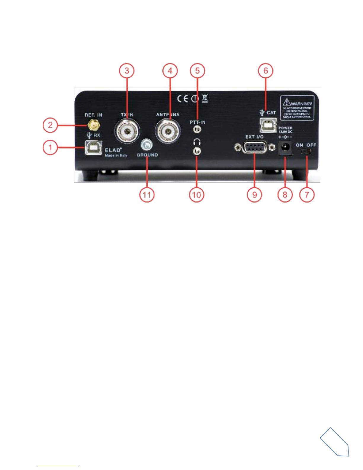
3.2 Rear Panel Description
1 - USB Receiver Data Connector
USB 2.0 port to connect with the PC. Please use the supplied cable.
2 - Frequency Reference Input
SMA 50 Ohm 10MHz, 0 dBm frequency reference input.
3 –TX IN Connector
M-type TX Input 50 Ohm antenna connector.
4 - Antenna Connector
M-type RX 50 Ohm antenna connector.
5 - PTT Input Connector
PTT Input to command the internal switch-box.
6 - CAT USB Serial Port
USB serial port for CAT communication.
7 - Power Switch
Turn On/Off the FDM-DUOr.
8 - Power supply
13.8V, 2.5A DC power supply connector.

ELAD FDM-DUOr User Manual Rev 0.04 12/2014
© 2014 ELAD S.r.l. All rights reserved. No part of this document may be reproduced, published, used, disclosed or disseminated in any form or
by any means, electronic, photocopying or otherwise, without prior written permission of ELAD S.r.l.
9
9 - Expansion Port
DB9 connector for external hardware. This is NOT a standard serial port.
Pin 1: SPI Latch
Pin 2: I2C SCL
Pin 3: SPI Clock
Pin 4: I2C SDA
Pin 5: Ground
Pin 6: TX Duo
Pin 7: RX Duo
Pin 8: SPI Data
Pin 9: +5V
10 –Speaker/Headphones Audio Output
The main FDM-DUOr audio output
11 –Ground Connector
For better performance and safety, connect to an earth ground using a short, heavy cable.

ELAD FDM-DUOr User Manual Rev 0.04 12/2014
© 2014 ELAD S.r.l. All rights reserved. No part of this document may be reproduced, published, used, disclosed or disseminated in any form or
by any means, electronic, photocopying or otherwise, without prior written permission of ELAD S.r.l.
10
3.3 Internal Hardware Description
Empty FDM-DUOr board
FDM-DUOr board with 3 filter modules
S1 ÷ S11
Eleven slots for filter modules from 1 to 11.
N.B. If FBPY Bypass module is used, it must be placed in Slot No. 11.

ELAD FDM-DUOr User Manual Rev 0.04 12/2014
© 2014 ELAD S.r.l. All rights reserved. No part of this document may be reproduced, published, used, disclosed or disseminated in any form or
by any means, electronic, photocopying or otherwise, without prior written permission of ELAD S.r.l.
11
3.3.1 ELAD Filter Module Family
Actual SFP-08 available filter modules (*)
Module Code
Module Description
Module Code
Module Description
FHP05M-1
High Pass 500 kHz
FBP17-1
Band Pass 17 m
FHP1M7-1
High Pass 1700 kHz
FBP15-1
Band Pass 15 m
FBP160-1
Band Pass 160 m
FBP12-1
Band Pass 12 m
FBP80-1
Band Pass 80 m
FBPY
Bypass module (**)
FBP40-1
Band Pass 40 m
FPCB-B3
Empty module for self-made filters
FBP30-1
Band Pass 30 m
FPCB-H5
Empty module for self-made filters
FBP20-1
Band Pass 20 m
(*) Please refer to ELAD website for updated list of filter modules.
(**) Bypass module is included with the FDM-DUOr.
3.3.2 FPCB-B3 Module Schematic

ELAD FDM-DUOr User Manual Rev 0.04 12/2014
© 2014 ELAD S.r.l. All rights reserved. No part of this document may be reproduced, published, used, disclosed or disseminated in any form or
by any means, electronic, photocopying or otherwise, without prior written permission of ELAD S.r.l.
12
3.3.3 FPCB-H5 Module Schematic
ELAD FDM-DUOr User Manual Rev 0.04 12/2014
© 2014 ELAD S.r.l. All rights reserved. No part of this document may be reproduced, published, used, disclosed or disseminated in any form or
by any means, electronic, photocopying or otherwise, without prior written permission of ELAD S.r.l.
13
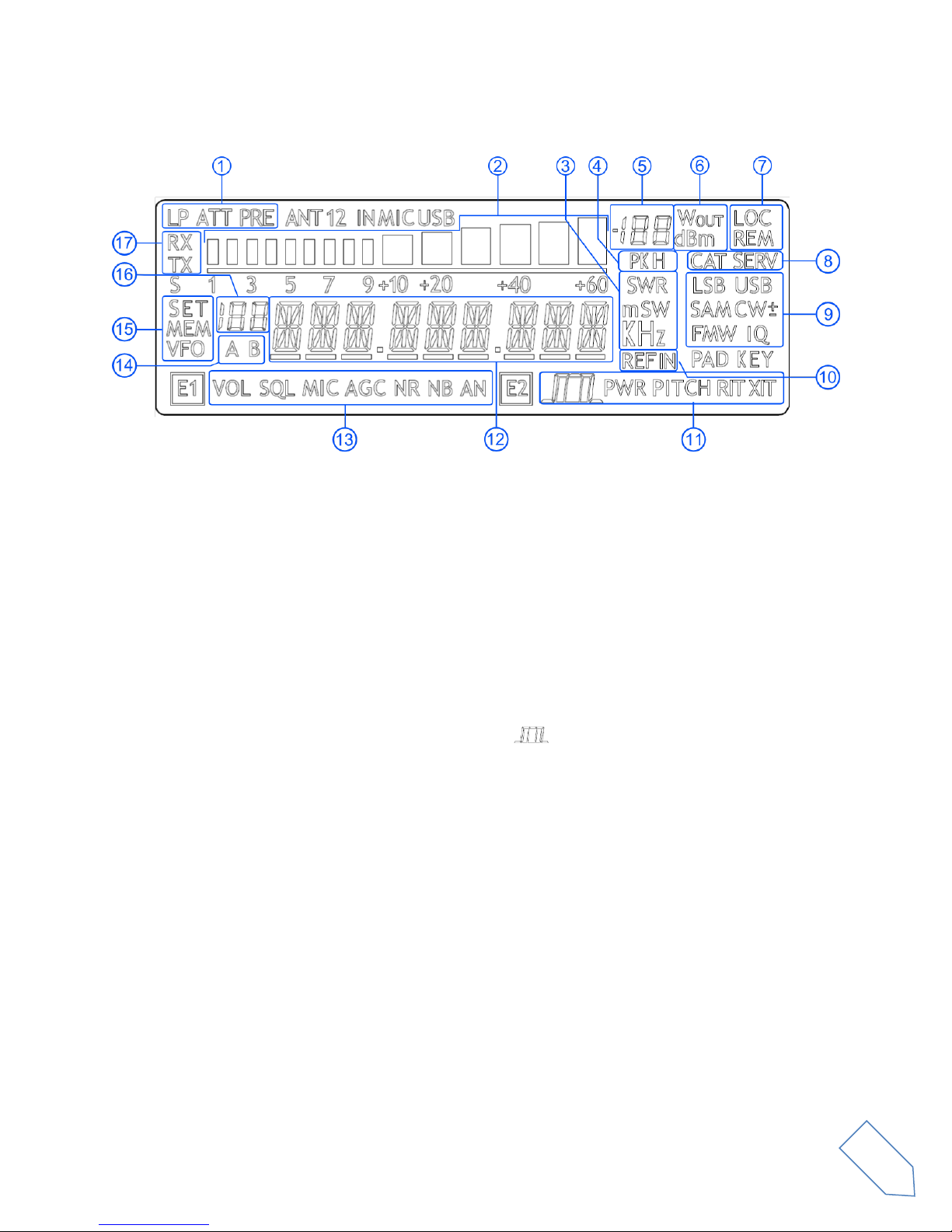
4LCD
1. LP: Low pass input filter active. ATT: input attenuation active.
2. Bar meter: in receiver mode displays the signal strength in S-units, in transmission mode
displays the forward power transmitted.
3. Measurements unit for the main display. The “S”of SWR is also used to indicate the “QuickStep”
function.
4. PK: blinks if the case of internal ADC overload.
5. Secondary display that displays the signal strength.
6. Measurement unit for the secondary display.
7. LOC: on when the Main Knob is locked.
8. CAT: on when a CAT command is received, SERV: Service mode enabled.
9. Operating mode.
10. External frequency reference present.
11. E2 Selected function. PITCH: CW pitch frequency, :Demodulation filter bandwidth.
12. Main display.
13. E1 Selected function. VOL: main volume, AGC: automatic gain control settings, NR: noise
reduction, NB: noise blanker.
14. Display the selected VFO.
15. SET: settings menu mode, MEM: memory mode, VFO: VFO mode
16. In memory mode, displays the selected memory index, in settings mode display the menu
number.
17. RX: receive, TX: internal switch box activated.

ELAD FDM-DUOr User Manual Rev 0.04 12/2014
© 2014 ELAD S.r.l. All rights reserved. No part of this document may be reproduced, published, used, disclosed or disseminated in any form or
by any means, electronic, photocopying or otherwise, without prior written permission of ELAD S.r.l.
14
5Quick Start
These instructions are intended only for a quick guide, detailed instructions are given later in this
manual
Turn on the FDM-DUOr using the rear panel switch. The receiver start in VFO mode with the
VFO-A selected.
Turn the E1 knob until you hear a suitable level of noise.
Use the Main knob to tune a frequency.
Press to select the desired communication mode.
Use the E2 to set the demodulation filter.

ELAD FDM-DUOr User Manual Rev 0.04 12/2014
© 2014 ELAD S.r.l. All rights reserved. No part of this document may be reproduced, published, used, disclosed or disseminated in any form or
by any means, electronic, photocopying or otherwise, without prior written permission of ELAD S.r.l.
15
6User Interface
6.1 VFO Mode
The VFO mode is the default mode of FDM-DUOr. Each VFO memorize the tuning frequency, mode and
tuning step
6.1.1 Tuning
In this mode, use the Main Knob to tune a frequency.
A short pressure on the main knob enter the frequency step menu
Use the main knob to modify the tuning step, then with a short pressure return in the VFO menu.
With a long pressure over the main knob, the Digit by Digit Frequency tuning mode is activated
In this mode use the main knob to modify the selected digit and E1 or E2 to change witch digit you want
to modify. Apply a short pressure on main knob to return in the standard tuning mode.

ELAD FDM-DUOr User Manual Rev 0.04 12/2014
© 2014 ELAD S.r.l. All rights reserved. No part of this document may be reproduced, published, used, disclosed or disseminated in any form or
by any means, electronic, photocopying or otherwise, without prior written permission of ELAD S.r.l.
16
6.1.2 E1 Receiver Settings
Apply a short pressure on the E1 knob to change the E1 selected parameter, the selected parameter
icon is turned on in the LCD. Turn until one click the E1 knob to display the parameter value, then turn
again E1 to modify the parameter value.
AGC: if the AGC is turned OFF (manual gain mode), the AGC icon blinks.
NR and NB: if the Noise Reducer or the Noise Blanker is turned on the relative NR or NB icon blinks.
6.1.3 E2 Receiver Settings
Apply a short pressure on the E2 knob to change the E2 selected parameter, turn until one click the E1
knob to display the parameter value, then turn again E1 to modify the parameter value.
6.1.4 Switch VFO
Use the button to switch VFO-A/B.
6.1.5 Store VFO to memory
Use the key to store the current VFO settings into a memory
Use E2 knob or main knob to select the destination memory and confirm with a short pressure on E2.

ELAD FDM-DUOr User Manual Rev 0.04 12/2014
© 2014 ELAD S.r.l. All rights reserved. No part of this document may be reproduced, published, used, disclosed or disseminated in any form or
by any means, electronic, photocopying or otherwise, without prior written permission of ELAD S.r.l.
17
6.1.6 “QuickMem” mode
Keep pressed the key to enter the “QuickMem” mode.
The memory channels 180 to 199 are reserved for the “QuickMem” selection. Keep pressed the key
until the desired frequency appears on the LCD display, then release the key and the current VFO is set
to the frequency and mode saved in the memory channel.
You can use the “FDM-DUOr Manager” feature in the ELAD FDM-SW2 software to customize the
memory channels.
6.1.7 VFO-A = VFO-B
With long pressure on key you get VFO-A = VFO-B
6.1.8 Change Operating Mode
With a short pressure on the button, you can change the receiver mode between the available
modes:
6.1.9 “QuickStep”
With a short pressure on the key, the “QuickStep”function is activated. This function quickly sets
the frequency step preset selected in the “QuickStep”setting menu, press again the key to set the
previous frequency step.
USB
CWAM
LSB

ELAD FDM-DUOr User Manual Rev 0.04 12/2014
© 2014 ELAD S.r.l. All rights reserved. No part of this document may be reproduced, published, used, disclosed or disseminated in any form or
by any means, electronic, photocopying or otherwise, without prior written permission of ELAD S.r.l.
18
6.2 MEM Mode
To activate the memory mode, apply a long pressure on .
6.2.1 Select and edit a memory
Use the main knob to select a memory. Apply a long pressure on the main encoder to enter the edit
memory menu. In this menu it is possible to modify the selected memory frequency in digit by digit
mode.
Use the button to select the VFO-A/B. This is useful if you want to set the memory settings to a
specific VFO.
6.2.2 Delete a memory
Apply a long pressure to the key to enter the delete menu
Use the E2 knob to set yes or no and make a short pressure on E2 to confirm.
6.2.3 Set memory to VFO
Use the key to set the selected VFO to the selected memory frequency and mode. When this
function is used, the FDM-DUOr automatically switches to the VFO mode.

ELAD FDM-DUOr User Manual Rev 0.04 12/2014
© 2014 ELAD S.r.l. All rights reserved. No part of this document may be reproduced, published, used, disclosed or disseminated in any form or
by any means, electronic, photocopying or otherwise, without prior written permission of ELAD S.r.l.
19
6.2.4 Change the memory display mode
Apply a short pressure on the key to show the memory label in the LCD main display. Press shortly
again to return to display the memory frequency.
You can use the “FDM-DUOr Manager” feature in the ELAD FDM-SW2 software to customize the
memory channels.

ELAD FDM-DUOr User Manual Rev 0.04 12/2014
© 2014 ELAD S.r.l. All rights reserved. No part of this document may be reproduced, published, used, disclosed or disseminated in any form or
by any means, electronic, photocopying or otherwise, without prior written permission of ELAD S.r.l.
20
6.3 Knobs functions
The following table describes the knob functions for some user interface menu :
Menu
Action
Main Knob
E1 Knob
E2 Knob
VFO
Value modified
Change selected VFO
frequency
Enter E1 selection
parameter
Enter E2 selection
parameter
Short Pressure
Enter STEP menu
Change E1 selected
parameter
Change E2 selected
parameter
Long Pressure
Switch to DIGIT by DIGIT
tuning mode
(2)
(2)
STEP
Value modified
Change tuning step value
Short Pressure
Exit from STEP Menu
Long Pressure
Switch to DIGIT by DIGIT
tuning mode
(2)
(2)
MEM
Value modified
Select next/previous
memory
Enter E1 selection
parameter
Enter E2 selection
parameter
Short Pressure
Change E1 selected
parameter
Change E2 selected
parameter
Long Pressure
Switch to DIGIT by DIGIT
tuning mode
(2)
(2)
E1 Selection:
VOL - AGC-
NR - NB
Value modified
Back to VFO or
MEM menu
Modify E1 selected
parameter value
Modify E2 selected
parameter value
Short Pressure
Back to VFO or
MEM menu
Change E1 selected
parameter
Change E2 selected
parameter
Long Press
Switch to DIGIT by DIGIT
tuning mode
(2)
(2)
E2 Selection:
FILTER - PITCH
Value modified
Back to VFO or
MEM menu
Modify E1 selected
parameter value
Modify E2 selected
parameter value
Short Pressure
Back to VFO or
MEM menu
Change E1 selected
parameter
Change E2 selected
parameter
Long Pressure
Switch to DIGIT by DIGIT
tuning mode
(2)
(2)
VFO > MEM
Value modified
Change the
destination memory
Change the
destination memory
Short Press
Save VFO in the
selected memory
Long Pressure
(2)
(2)
Delete MEM
Value modified
Change Yes/No
Short Pressure
Confirm Yes/No
Long Pressure
SETUP -
PARAMETER
CHOICE
(MENU button)
Value modified
Change parameter
selection
Short Press
Enter parameter setup
menu
Long Pressure
Other manuals for FDM-DUOr
1
Table of contents
Other ELAD Receiver manuals


