Fracarro HOME FIBRE OPT-RX 4 MICRO User manual

ISTRUZIONI PER L’USO
OPERATING INSTRUCTIONS
HOME FIBRE
OPT-RX 4 MICRO
OPT-RX QUAD MICRO

2
Italiano
1. AVVERTENZE PER LA SICUREZZA
L’installazione del prodotto deve essere eseguita da personale qualificato in conformità alle leggi e normative locali sulla sicurezza.
Fracarro Radioindustrie di conseguenza è esonerata da qualsivoglia responsabilità civile o penale conseguente a violazioni delle
norme giuridiche vigenti in materia e derivanti dall’uso del prodotto da parte dell’installatore, dell’utilizzatore o di terzi.
L'installazione del prodotto deve essere eseguita secondo le indicazioni di installazione fornite, al fine di preservare l'operatore da
eventuali incidenti e il prodotto da eventuali danneggiamenti
Avvertenze per l’installazione
Il prodotto non deve essere esposto a gocciolamento o a spruzzi d’acqua e va pertanto installato in un ambiente asciutto,
all’interno di edifici.
Umidità e gocce di condensa potrebbero danneggiare il prodotto. In caso di condensa, prima di utilizzare il prodotto,
attendere che sia completamente asciutto. Maneggiare con cura. Urti impropri potrebbero danneggiare il prodotto.
Lasciare spazio attorno al prodotto per garantire una ventilazione sufficiente. L’eccessiva temperatura di lavoro e/o un
eccessivo riscaldamento possono compromettere il funzionamento e la durata del prodotto.
Non installare il prodotto sopra o vicino a fonti di calore o in luoghi polverosi o dove potrebbe venire a contatto con
sostanze corrosive.
In caso di montaggio a muro utilizzare tasselli ad espansione adeguati alle caratteristiche del supporto di fissaggio. La
parete ed il sistema di fissaggio devono essere in grado di sostenere almeno 4 volte il peso dell’apparecchiatura.
Attenzione: per evitare di ferirsi, questo apparecchio deve essere assicurato alla parete/pavimento secondo le istruzioni
di installazione.
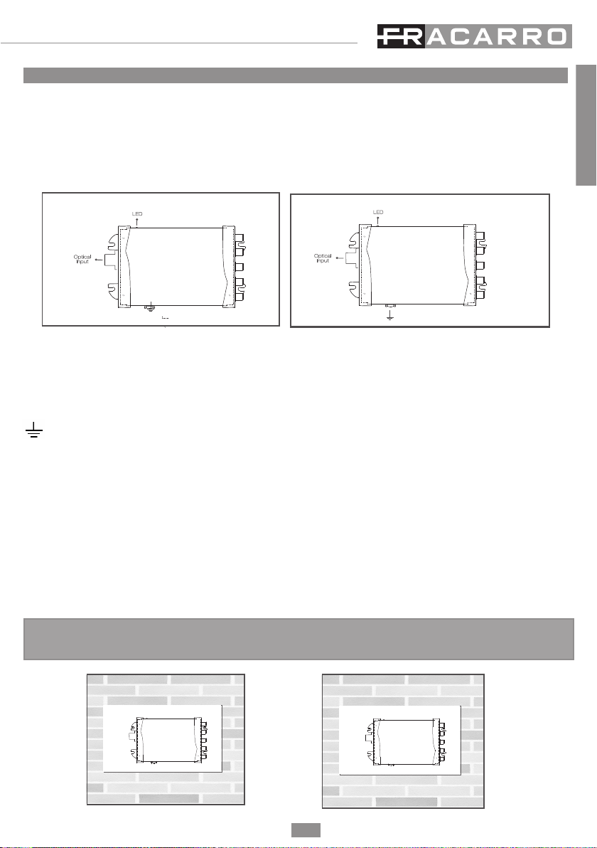
Il prodotto deve essere collegato all’elettrodo di terra dell’impianto d’antenna conformemente alla norma EN 60728-11.
La vite predisposta per tale scopo è contrassegnata con il simbolo .
Si raccomanda di attenersi alle disposizioni della norma EN 60728-11 e di non collegare tale vite alla terra di protezione
della rete elettrica di alimentazione.
Non guardare mai dentro ai connettori ottici del prodotto. La radiazione laser non è visibile ad occhio nudo e quindi non
è possibile prevenire un danno a lungo termine.
Quando si lavora con i connettori ottici del partitore, controllare sempre che i laser di eventuali trasmettitori ottici ad
esso collegati, siano spenti.
Simbolo di terra dell’impianto d’antenna
.Avvertenze generali
In caso di guasto non tentate di riparare il prodotto altrimenti la garanzia non sarà più valida.
Le informazioni riportate in questo manuale sono state compilate con cura, tuttavia Fracarro Radioindustrie S.r.l. si riserva il diritto
di apportare in ogni momento e senza preavviso, miglioramenti e/o modifiche ai prodotti descritti nel presente manuale.
Consultare il sito www.fracarro.com per le condizioni di assistenza e garanzia.

OPT-RX QUAD MICRO
OPTICAL INPUT: connettore SC/APC di ingresso del ricevitore ottico. Usato per il link in fibra per i segnali delle polarizzazioni
satellitari e per i segnali TV.
TV+SAT OUT: 4 connettori F per uscite miscelate TV+SAT (87 ÷ 862MHz , 950 ÷ 2150MHz)
DC IN OPTIONAL: ingresso F alimentazione supplementare per un alimentatore esterno (12 ÷ 18V).
LED multifunzione: acceso (verde): normale funzionamento (correttamente alimentato).
lampeggiante veloce: anomalia hardware.
lampeggiante lento: potenza ottica al di fuori del range operativo.
Messa a terra dell’impianto d’antenna (secondo EN60728-11)
OPT-RX 4 MICRO
OPTICAL INPUT: connettore SC/APC di ingresso del ricevitore ottico. Usato per il link in fibra per i segnali delle polarizzazioni
satellitari e per i segnali TV.
TV OUT: 1 connettore F per uscita segnale TV (87 ÷ 862MHz )
SAT OUT: 4 connettori F per uscita 4 polarità SAT (950 ÷ 2150MHz ) con ingresso DC
LED multifunzione: acceso (verde): normale funzionamento (correttamente alimentato).
lampeggiante veloce : anomalia hardware.
lampeggiante lento: potenza ottica al di fuori del range operativo.
Messa a terra dell’impianto d’antenna (secondo EN60728-11)
3
Italiano
2. DESCRIZIONE DEL PRODOTTO
Il ricevitore
OPT-RX QUAD MICRO
converte il segnale ottico in ingresso in segnale RF, disponibile su 4 uscite universali. Il ricevitore
mette a disposizione a 4 diversi utenti il segnale TV e SAT con tutti i servizi e contenuti offerti dai broadcaster come se fossero
direttamente connessi alla propria antenna o parabola.
Il dispositivo ha un basso cunsumo energetico e può essere alimentato direttamente da STB (Set-top box).
Il ricevitore
OPT-RX 4 MICRO
converte il segnale ottico in ingresso in segnale RF, disponibile su 4 uscite indipendenti SAT V
L
, H
L
, V
H
, H
H
e
1 TV per la distribuzione di impianti a multiswitch. Il prodotto è telealimentabile tramite le uscite SAT.
OPT-RX QUAD MICRO
3. INSTALLAZIONE DEL PRODOTTO
3.1 Installazione
OPT-RX
QUAD MICRO
OPT-RX
4 MICRO
}
TV+SAT
Output
DC IN
}
SAT Pol.
Output
TV output
OPT-RX 4 MICRO

4
Italiano
3.2 Alimentazione
OPT-RX QUAD MINI: Il ricevitore in fibra può essere alimentato da STB (set-top box) oppure con l’uso di un alimentatore esterno
nel connettore d’ingresso DC IN optional.
OPT-RX 4 MINI: telealimentare il dispositivo attraverso le uscite SAT.
3.3 Collegamento fibra ottica
ATTENZIONE: Non è possibile effettuare un collegamento ottico diretto tra OPT-TX DT e i ricevitori OPT-RX QUAD
MINI o OPT-RX 4 MINI. Un link punto punto è possibile solo utilizzando appositi attenuatori ottici di linea in quanto la potenza
massima in ingresso dei ricevitori ottici OPT-RX QUAD MINI e OPT-RX 4 MINI non può superare -8dBm.
Verificare il livello ottico del segnale sulla fibra tramite un misuratore ottico prima di collegarla al ricevitore.
Utilizzare le bretelle SC-APC -> MINI (PR Adpt, cod. 287226) per collegare i dispositivi OPT alla distribuzione ottica (dispositivi
VOV e VOT).
Attenzione: Per preservare e proteggere le superfici di contatto dei connettori ottici è necessario mantenere le protezioni di
bussole e ferule in posizione fino al momento della connessione o l’eventuale pulizia tramite appositi strumenti dedicati.
4. ISTRUZIONI PER L’UTILIZZO
4.1 Dimensionamento di un impianto in fibra ottic
L’attenuazione ottica di tratta consentita al sistema deve essere compresa tra 15 e 21dB ottici. Fare riferimento alle caratteristiche
tecniche dei componenti passivi che compongono distribuzione per calcolare l’attenuazione di tratta.
Il ricevitore OPT-RX QUAD MINI garantisce un adeguato livello del segnale TV e SAT alla presa utente se il segnale ottico al suo
ingresso è compreso tra -8dBm e -14dBm ottici e il segnale RF in ingresso all’OPT-TX DT rispetta le indicazioni riportate nel
manuale del trasmettitore.ATTENZIONE:
• Non sono ammessi collegamenti diretti tra OPT-TX DT e OPT-RX, a meno dell’ utilizzo di opportuni attenuatori ottici di
linea
• E’ indispensabile utilizzare un misuratore di segnale ottico per verificare il livello ottico d’ingresso al ricevitore ed evitare di
danneggiare il fotodiodo ricevente (potrebbe danneggiarsi se il segnale in ingresso è superiore a 0dBm).
4.2 Livelli in uscita al ricevitore ottico
Il livello in uscita dai ricevitori ottici OPT-RX dipende dal numero di segnali trasmessi in fibra e dell’attenuazione ottica della tratta.
Si tenga conto che 1dB di perdita ottica equivale a 2dB di attenuazione al livello elettrico (RF).
OPT-RX QUAD MICRO
Di seguito vengono riportati alcuni livelli di riferimento dei segnali RF in uscita al ricevitore OPT-RX QUAD MICRO in funzione
del livello di potenza ottica in ingresso :
Tab.1 indicazioni livelli di uscita all’OPT-RX QUAD MICRO
Nota: 1dB ottico equivale a 2dB a livello elettrico (RF).
Livello RF in uscita per MUX TV Livello RF in uscita per TP SAT
Numero MUX Livelli ottici al ricevitore
-14 ÷ -8 dBm
Numero TP Livelli ottici al ricevitore
-14 ÷ -8 dBm
40 60 ÷ 72 40 62 ÷ 74
16 64 ÷ 76 16 66 ÷ 78
8 67 ÷ 79 8 69 ÷ 81
4 70 ÷ 82 4 72 ÷ 84

5
Italiano
FM, DAB e DVB-T
Il livello dei segnali FM e DAB deve essere di 10dB inferiore ai segnali DVB-T.
I livelli dei segnali alle prese utenti devono rispettare i valori imposti dalla normativa EN50083-7 (DVB-T: 45÷74dBuV, SAT:
47÷77dBuV). In alcuni casi sarà necessario attenuare il segnale RF in uscita dal ricevitore o, se possibile, il segnale ottico al suo
ingresso tramite componenti passivi quali attenuatori ottici di linea.
OPT-RX 4 MICRO
Di seguito vengono riportati alcuni livelli di riferimento dei segnali RF in uscita al ricevitore OPT-RX 4 MICRO in funzione
del livello di potenza ottica in ingresso:
Tab.2 indicazioni livelli di uscita all’OPT-RX DT QUATTRO.
NOTA: 1dB ottico equivale a 2dB a livello elettrico (RF).
FM, DAB e DVB-T
Il livello dei segnali FM e DAB deve essere di 10dB inferiore ai segnali DVB-T.
5. ESEMPI TIPICI DI IMPIANTO
Alcuni schemi di esempio sono disponibili nelle ultime pagine del manuale e nel sito www.fracarro.com
6. SPECIFICHE TECNICHE
Livello RF in uscita per MUX TV Livello RF in uscita per TP SAT
Numero MUX Livelli ottici al ricevitore
-14 ÷ -8 dBm
Numero TP Livelli ottici al ricevitore
-14 ÷ -8 dBm
40 66 ÷ 78 40 68 ÷ 80
16 70 ÷ 82 16 72 ÷ 84
8 73 ÷ 85 8 75 ÷ 87
4 76 ÷ 88 4 78 ÷ 90
OPT-RX QUAD MICRO
Codice Fracarro 2706
Ingresso Ottico N.° 1 SC/APC
Ingresso F Power N.° 1 Alimentazione 12 ÷ 18 V
Uscite RF N.° 4 Universali (TV+SAT)
Ingresso Ottico
Connettore Ottico SC/APC
Return Loss ottico dB >45
Potenza ottica in ingresso (min ÷ max) dBm -8 ÷ -14

6
Italiano
Uscite RF
Banda MHz 87 ÷ 862 / 950 ÷ 2150
Tipo di connettore F femmina
Return Loss dB 10
Livello d’uscita totale @ -14 dBm dBµV 76 ± 5 (TV), 78 ± 5 (SAT)
Controllo porte d’uscita Diseqc
Caratteristiche Principali
Tensione di alimentazione V 12÷18 V
Potenza consumata W 2,8 W
Assorbimento A 200 mA (13V) - 155 mA (18V)
Temperatura di lavoro °C -5 ÷ +50
Segnalazioni luminose Led verde di alimentazione/stato
Dimensioni mm 120x100x30
OPT-RX 4 MICRO
Codice Fracarro 2706
Ingresso Ottico N.° 1 SC/APC
Uscite RF N.° 5 (4 Polarità SAT + 1 TV)
Ingresso Ottico
Connettore Ottico SC/APC
Return Loss ottico dB >45
Potenza ottica in ingresso (min ÷ max) dBm -8 ÷ -14
Uscite RF
Banda MHz 87 ÷ 862 / 950 ÷ 2150
Tipo di connettore F femmina
Return Loss dB 10
Livello d’uscita totale @ -14 dBm dBµV 82 ± 5 (TV), 84 ± 5 (SAT)
Caratteristiche Principali
Tensione di alimentazione V 12÷18 V su VL HL VH HH
Potenza consumata W 2,5 W
Assorbimento A 180 mA (13V) - 135 mA (18V)
Temperatura di lavoro °C -5 ÷ +50
Segnalazioni luminose Led verde di alimentazione/stato
Dimensioni 120x100x30

7
English
1. SAFETY WARNINGS
The product can only be installed by qualified personnel in compliance with local safety laws and regulations. Fracarro
Radioindustrie is free from all civil and criminal responsibility due to breaches of current legislation derived from the improper
use of the product by the installer, user or third parties
The product must be used in full compliance with the instructions given in this manual, in order to protect the operator against
all possible injury and the product from being damaged.
INSTALLATION WARNINGS
The product must not be exposed to water drips and must be installed indoors inside in dry places.
Damp and condensation drops could damage the product. Consequently, always wait for the product to be perfectly
dry before use. Handle with care. Knocks could damage the product. Leave plenty of space around the product to
ensure sufficient ventilation. High temperatures or overheating could compromise the product functions and life.
Do not install the product above or close to sources of heat, in dusty atmospheres or when it could be exposed to
corrosive substances.
If the product is installed on the wall, use proper expansion bolts suitable to the fixing support. The wall and the
fixing support must be able to bear at least 4 times the equipment weight.
Attention: to avoid being hurt, the unit must be mounted to the wall/floor according to the installation instructions.
The unit must be connected to the ground electrode of the antenna system, in compliance with the EN 60728-11
standard. The earth screw is indicated with the symbol.
It is important to observe the provisions of the EN60728-11 standard and not to connect this screw to the power
supply earth line.
Never look inside the optical connectors of the product. Laser radiation is not visible to the naked eye and serious
long-term damage could be caused.
Ensure that any optical transmitter lasers are turned off before working on the split optical connectors.
Ground symbol of the antenna system
.
GENERAL WARNINGS
In the event of a malfunctioning, do not try to fix the product as the guarantee would be invalidated.
Although the information given in this manual has been prepared carefully and thoughtfully, FracarroRadioindustrie S.r.l. reserves
the right to modify it without notice and to improve and/or modify the product described in this manual. See the website
www.fracarro.com to have information relevant to the technical support and product guarantee.

8
English
2. PRODUCT DESCRIPTION
The
OPT-RX QUAD MICRO
receiver converts the incoming optical signal into 4 universal outputs. The receiver provides for four
different utents the TV and SAT signal, with all services and products offered by broadcaster, as if they were directly connected to
an independant aerial or dish.
The product has a low power consuption and it can be powered directly from a STB (set-top-box).
The
OPT-RX 4 MICRO
receiver converts the incoming optical signal into 4 independent outputs SAT V
L
, H
L
, V
H
, H
H
and 1 TV for
multiswitch installations. The product can be supplied via the SAT outputs.
OPT-RX QUAD MICRO
OPTICAL INPUT: SC-APC input connector for the optical receiver. Used for the fibre link for the satellite polarisation and TV
signals.
TV + SAT OUT: 4 F connector for mixed TV+SAT outputs (87 to 862MHz , 950 to 2150MHz).
DC IN OPTIONAL: F DC input optional to power the receiver with an external power supply (12-18V).
POWER ON LED: On (green) to show the product is turned on;
fast blinking: HW fault; slow blinking: optical power received out of correct range
Aerial system earth connection (according to EN60728-11 standard).
OPT-RX 4 MICRO
OPTICAL INPUT: SC-APC input connector for the optical receiver. Used for the fibre link for the satellite polarisation and TV
signals.
TV OUT: 1 F connector for TV signal output (87 to 862MHz ).
SAT OUT: 4 F connectors for output 4 SAT polarities (950 to 2150MHz ) with DC input.
POWER ON LED: On (green) to show the product is turned on;
fast blinking: HW fault; slow blinking: optical power received out of correct range
Aerial system earth connection (according to EN60728-11 standard).
3. RODUCT INSTALLATI
The receivers OPT- RX QUAD MICRO and OPT-RX4 MICRO can be wall mounted using the brackets incorporated in the product
mechanics. The space is provided for connecting the power lead and for correct ventilation of the product (see figures below).
3. PRODUCT INSTALLATION
3.1 Installation
}
TV+SAT
Output
DC IN
OPT-RX QUAD MICRO
}
SAT Pol.
Output
TV output
OPT-RX 4 MICRO
OPT-RX
QUAD MICRO
OPT-RX
4 MICRO

9
English
3.2 Power supply
OPT-RXQUAD MICRO: The optical receiver can be powered by STB (set-top-box) or with an external power supply to DC IN optional
input.
OPT-RX 4 MICRO: the power supply is provided via SAT outputs.
3.3 Fibre optic connection
ATTENTION: Direct connections are not allowed between the OPT-TX DT and OPT-RX QUAD MICRO/ OPT-RX DT
4 MICRO unless the correct line optical attenuators are used, because the maximum input power into the receivers can not
exceed -8dBm.
An optical power meter must be used to check the optical input power to the receivers.
Use the SC-APC -> MINI links (PR ADAPT, code 287226) to connect the OPT devices to the optical distribution (VOV and VOT
devices).
Attention: To conserve and protect the contact surfaces of the optical connectors the protective caps must be
left in position until when the connections are made or can be cleaned using the correct tools.
4. USER’S INSTRUCTIONS
4.1 Dimensioning a Fibre Optic system
The optical attenuation range allowed is 15 to 21 optical dB. Refer to the product specifications to calculate the optical attenuations
for the devices.
The receivers can guarantee that the correct level of TV and SAT signals are available to the end users sockets. This guarantee
is on the provision that the input level of the optical signal is between -8dBm and -14dBm and the RF signal incoming to
the OPT-TXDT complies with the specifications of its manual.
ATTENTION:
• Direct connections are not allowed between the OPT-TX DT and Receivers, unless the correct line optical
attenuators are used.
• An optical power meter must be usedto check the optical input powerto the receivers and to prevent damaging the receiving
photodiode (damage can be caused if the optical input signal is higher than 0dBm).
The output level to the OPT-RX optical receivers depends on the number of signals transmitted through the fibreand the optical
attenuation of the section.
Remember that 1dB of optical fall equals 2dB of attenuation to the electric level (RF).
Below some reference levels are given for the output signals to the receivers.
OPT-RX QUAD MICRO
Shown below are some of the reference levels of the signals output to the receiver OPT-RX QUAD MICRO
Table 1: Indications of output levels to the OPT-RX QUAD MICRO.
Note: 1dB optical equals 2dB at electric level (RF).
RF output level for MUX TV RF output level for TP SAT
No. for MUX Optical input power
-14 to -8 dBm
Numero TP Optical input power
-14 to -8 dBm
40 60 to 72 40 62 to 74
16 64 to 76 16 66 to 78
8 67 to 79 8 69 to 81
4 70 to 82 4 72 to 84
4.2 Output levels to the optical receiver

10
English
FM, DAB and DVB-T
The FM and DAB signal levels must be 10dB lower than DVB-T.
The signal levels to the user sockets must respect the set points given inthe EN50083-7 standard (DVB-T: 45-74dBµV, SAT: 47-
77dBµV). In certain cases the RF output signal from the receiver, or if possible the input optical signal, will have to be attenuated
by means of passive components such as optical line faders.
OPT-RX 4 MICRO
Shown below are some of the reference levels of the signals output to the receiver OPT-RX 4 MINI:
Table 2: Indications of output levels to the OPT-RX 4 MICRO.
Note: 1dB optical equals 2dB at electric level (RF).
FM, DAB and DVB-T
The FM and DAB signal levels must be 10dB lower than DVB-T.
Some example diagrams are available at the end of the manual and on the website www.fracarro.com
5- TYPICAL INSTALLATION EXAMPLES
OPT-RX QUAD MICRO
Fracarro code 2706
Optical input N.° 1 SC/APC
Input Dc Optional N.° 1 Input power 12-18 V
RF Outputs N.° 4 Universal (TV+SAT)
Optical Input
Optical connector SC/APC
Optical Return Loss dB >45
Optical power (min ÷ max) dBm -8 to -14
RF output level for MUX RF output level for TRANSPONDER
No. of MUX Optical input power
-14 ÷ -8 dBm
Numero TP Optical input power
-14 ÷ -8 dBm
40 66 to 78 40 68 to 80
16 70 to 82 16 72 to 84
8 73 to 85 8 75 to 87
4 76 to 88 4 78 to 90

11
English
RF Outout
Bandwidth MHz 87 to 862 / 950 to 2150
Connector type F female
Return Loss dB 10
RF total output level @ optical -14 dBm dBµV 76 ± 5 (TV), 78 ± 5 (SAT)
Output Sat control Diseqc
Main Features
Main Voltage V 12 to 18 V
Power comsumption W 2,8 W
Current comsumption A 200 mA (13V) - 155 mA (18V)
Operating temperature °C -5 to +50
Led information Green led Power/status
Dimension LxHxW mm 120x100x30
OPT-RX 4 MICRO
Fracarro code 2706
Optical input N.° 1 SC/APC
RF outputs N.° 5 (4 SAT + 1 TV)
Optical input
Optical connector SC/APC
Optical Return Loss dB >45
Optical power (min ÷ max) dBm -8 to -14
RF Output
Bandwidth MHz 87 to 862 / 950 to 2150
Connector type F female
Return Loss dB 10
RF total output level @ optical -14 dBm dBµV 82 ± 5 (TV), 84 ± 5 (SAT)
Main Features
Main Voltage V 12 to 18 V on VL HL VH HH
Power comsumption W 2,5 W
Current comsumption A 180 mA (13V) - 135 mA (18V)
Operating temperature °C -5 to +50
Led information Green led Power/status
Dimension LxHxW 120x100x30

12
Schema HVHV e DCSS
Scheme HVHV and DCSS
ESEMPI TIPICI DI IMPIANTO
APPLICATION EXAMPLE
Attenzione:
• l’indicazione delle antenne, del centralino o eventuali preamplificatori riportati negli schemi è puramente indicativa in
quanto la scelta dipende esclusivamente dalla tipologia del segnale ricevuto nella zona di realizzazione dell’impianto.
• I livelli alle prese dipendono dai segnali trasmessi e dal livello ottico in ingresso all’OPT-RX(vedi capitolo 4).
• I valori ottici riportati negli schemi sono calcolati sulla base dei valori medi di specifica dei componenti passivi utilizzati.
Warning:
• The choice of antennas, dishes and multiband amplifiers are shown purely as an indication of a typical example. Care must
be taken to ensure that the correct equipment is used to optimise both signal strength and quality based on the geographical
location of the intended installation.
• RF outlet levels at the receivers are dependant on the number of transmitted signals over the fibre and to the optical input
level at the receiver (see chapter 4).
• Optical levels shown in thefollowing designs are calculated using the typical attenuation values for the passive components
used.
OPT-RX
OPT-TX
4 MICRO

13
Schema 1 calata, 9 piani
Scheme 1 trunk line, 9 floors

14
Schema 2 posizioni orbitali + DVB-T
Scheme 2 orbital positions + DVB-T

15
Schema Radiale 1TX 16div-opzione
Star distribution system 1 TX split into 16

Fracarro Radioindustrie SRL
Via Cazzaro n.3 - 31033 Castelfranco Veneto (TV) - ITALIA - Tel: +39 0423 7361 - Fax: +39 0423 736220
.
Fracarro France S.A.S.
7/14 rue du Fossé Blanc Bâtiment C1 - 92622 Gennevilliers Cedex - FRANCE Tel: +33 1 47283400 - Fax: +33 1 47283421
Fracarro (UK) - Ltd
Unit A, Ibex House, Keller Close, Kiln Farm, Milton Keynes MK11 3LL UK - Tel: +44(0)1908 571571 - Fax: +44(0)1908 571570
www.fracarro.com - info@fracarro.com - supportotecnico@fracarro.com - chat whatsapp +39 335 7762667
Garantito da/ Guaranteed by/ Garanti par/ Garantizado por/ Garantido por/ Garantiert durch/
Zajamčena od/
Garantirano od/ Garantovano od/ Gwarantowane przez
I: CONFORMITÀ ALLE DIRETTIVE EUROPEE
GB: EUROPEAN DIRECTIVES CONFORMITY
IT: CONFORMITA’ ALLE DIRETTIVE EUROPEE
Fracarro dichiara che il prodotto è conforme alle direttive 2014/53/UE e 2011/65/UE. Il testo completo della dichiarazione di
conformità UE è disponibile al seguente indirizzo internet ce.fracarro.com.
EN: CONFORMITY TO EUROPEAN LAWS
Fracarro declares that the product complies with EU Directive 2014/53 and 2011/65/UE. The full text of the EU Declaration of
Conformity is available on the following website ce.fracarro.com.
INFORMAZIONE AGLI UTENTI
A sensi dell’art. 26 del Decreto Legislativo 14 marzo 2014, n. 49 "Attuazione della direttiva 2012/19/UE sui rifiuti di
apparecchiature elettriche ed elettroniche (RAEE)"
Il simbolo del cassonetto barrato riportato sull’apparecchiatura indica che il prodotto alla fine della propria vita
utile deve essere raccolto separatamente dagli altri rifiuti. L’utente dovrà, pertanto, conferire l’apparecchiatura
giunta a fine vita agli idonei centri di raccolta differenziata dei rifiuti elettronici ed elettrotecnici, oppure
riconsegnarla al rivenditore al momento dell’acquisto di una nuova apparecchiatura di tipo equivalente, in
ragione di uno a uno. L’adeguata raccolta differenziata per l’avvio successivo dell’apparecchiatura dismessa al
riciclaggio, al trattamento e allo smaltimento ambientalmente compatibile contribuisce ad evitare possibili
effetti negativi sull’ambiente e sulla salute e favorisce il riciclo dei materiali di cui è composta
l’apparecchiatura.
USER’S INFORMATION
Disposal of Old Electrical & Electronic Equipment (Applicable in the European Union and other European countries with
separate collection system)
This symbol on the product or on its packaging indicates that this product shall not be treated as household
waste. Instead it shall be handed over to the applicable collection point for the recycling of electrical and
electronic equipment. By ensuring this product is disposed of correctly, you will help prevent potential
negative consequences for the environment and human health, wich could otherwise be caused by
inappropriate waste handling of this product. The recycling of materials will help to conserve natural
resources. For more detailed information about recycling of this product, please contact your local city office,
your household waste disposal service or the shop where you purchased the product.
3IS737 - 12/10/2018
This manual suits for next models
2
Table of contents
Languages:
Other Fracarro Receiver manuals

Fracarro
Fracarro KDSR User manual

Fracarro
Fracarro OPT-TX54 User manual

Fracarro
Fracarro HOME FIBRE OPT-RX 4 MINI User manual

Fracarro
Fracarro KDSR User manual

Fracarro
Fracarro OPT-RX SCD2 User manual

Fracarro
Fracarro HOME FIBRE OPT-TX DT User manual

Fracarro
Fracarro UTP-4RXA User manual

Fracarro
Fracarro OPT 3US TX User manual