ELAN AUDIO SENTINEL RCU-01 User manual

ELANAUDIO
SENTINEL / RCU-01
Remote Control System
Owners Manual
RCU01R02
ELAN Audio
2 STEEL COURT
SOUTH GUILDFORD WA 6055
PHONE (08) 9277 3500
FAX (08) 9478 2266
www.elan.com.au
techsupport@elan.com.au

ELAN AUDIO - SENTINEL / RCU-01 RCU01R02 PAGE 1/49
Contents List
1. SENTINEL / RCU-01 Product Overview
2. Packing list
3. SENTINEL System Specifications
4. Initial setup
4.1 Install the SENTINEL package
4.2 Upgrade from a previous SENTINEL Version
4.3 Connect the RCU to the PC
4.4 Run SENTINEL and check Comms
4.5 Configure Paging. (optional)
4.6 Configure a site and download to the RCU
4.7 Configure a modem for use with the RCU
4.8 Configure a Wavecom WM02 modem(optional)
4.9 Configure Local Alarms(optional)
5. SENTINEL Operational Overview V2.2.0
6. RCU-01 Operation
7. SENTINEL Technical Reference
7.1 Installation
7.2 Host / RCU Communications
7.3 Connect to Site
7.4 Site Status
7.5 Site Configuration
7.6 Alarms
7.7 Hardware Configuration
7.8 Site General Configuration
7.9 Site Analog Input Configuration
7.10 Site Status Input Configuration
7.11 Site Control Output Configuration
7.12 Site Panel LED Configuration
7.13 Site Control Security
7.14 Site Mains Alarm Configuration
7.15 Site Paging Configuration
7.16 Host Paging Configuration
7.17 Events
7.18 Paging User Edit
7.19 SENTINEL diagnostic and Data storage
8. RCU-01 Description
8.1 Front Panel Operation
8.2 Change Connection type
8.3 Operating the Relay Outputs
8.4 I/O Considerations
8.5 ANALOG Input Pinouts
8.6 Digital Input Pinouts
8.7 Relay Output Pinouts
8.8 Diagnostic features
8.9 RCU Diagnostic Mode
8.10 Direct connecting by TTY terminal
8.11 Internal addressing of I/O cards
9. Warranty Information
10. Appendix
RCU-01 Front / Rear Panel Schematic
SENTINEL UHF / PSTN / Landline Examples

ELAN AUDIO - SENTINEL / RCU-01 RCU01R02 PAGE 2/49
1. SENTINEL / RCU-01 Product Overview
The SENTINEL Remote Control System is designed and built in Western Australia by ELAN Audio.
At its most basic, a system consists of an RCU-01 at the 'Remote Site' and a PC at the 'Control Site' running
SENTINEL software.
The SENTINEL System is primarily designed to control Radio and Television Broadcast Transmitter installations, but
is equally suitable for control of equipment in Industrial Systems and Installations.
Up to 100 'Remote Site' units can share the Computer located at the 'Control Site'.
Communication between 'Remote Sites' and the 'Control Site' is Digital using 'Modems' via one or more of the
following paths.
•Public Subscriber Telephone Network. PSTN.
•Analog Portable Telephone.
•Digital Portable Telephone.
•2 Wire Leased or Private Line.
•4 Wire Leased or Private Line.
•Analog Sub Carriers.
•UHF Half Duplex Transceiver.
The SENTINEL System is designed to be 'Open Ended' allowing expansion to the basic RCU-01 'Remote Site' unit
and to the 'Control Site' Equipment.
The RCU-01 is 19" Rack Mounting requiring 2RU of rack space.
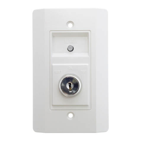
The front panel features an illuminated 2 line x 16 character LCD display, 16 Legendable LED status indicators, Power
and Data Transmission status indicator LEDs, Safety Key Lock, Activate Button and 4 Function Control Buttons.
The rear panel features AC Mains inlet and AC Fuse, Backup Battery connector, 9 / 12 V DC Modem Power supply
connector, RS-232 Modem Data connector, RS-485 Serial Bus Connector and 6 x 25 pin 'D' connectors, each
servicing 8 control inputs or outputs.
Standard configuration of the RCU-01 is as follows.
•8 Analog Inputs.
•24 Opto Isolated Inputs.
•16 Relay Outputs.
Alternate options are
•8 Analog Inputs.
•16 Opto Isolated Inputs..
•24 Relay Outputs.
•0 Analog Inputs
•24 Opto Isolated Inputs
•24 Relay Outputs
As standard, the RCU-01 Basic 'Remote Site' unit is supplied with the following
•AC Power cable.
•Battery Connector.
•Modem Power Supply Connectors.
•Owners Manual.
•Operators Manual.
Additional items required for operation of the RCU-01
•12V 7AH Lead Acid Rechargeable Gel- Cell.
•Approved Modem. (The Maestro "Woomera" Industrial Modem)
( Not required when using Radio Transceiver with built in Modem)
Recommended for RCU-01 Control Site
•Mains AC and Telephone Surge Protector.
( i.e. Dick Smith - F2852 ; Altronics - P8130 ; Jaycar - MS4025)

ELAN AUDIO - SENTINEL / RCU-01 RCU01R02 PAGE 3/49
The 12V 7AH Gel Cell is a common Re-chargeable battery, and available off the shelf from most electronics
component suppliers. ELAN Audio is unable to supply and ship these batteries by air with the RCU-01, as they
are prohibited as general Air Cargo.
ELAN Audio recommends and supplies the Maestro "Woomera" Modem. The Maestro "Woomera" is an
Industrial Modem having a number of special features, including the ability to operate from 9V DC supplied from
the RCU-01, which is essential to maintain communication with a remote site during mains power failures.
Further development is planned for the SENTINEL system where external 'Intelligent' units will plug into the RS-
485 Serial Port and expand the Input and Output numbers, and also manage 'Pairs of Transmitters' making the
SENTINEL system suitable and economical for use on shared Transmitting sites.
Control Site
Minimum Hardware Requirements
•PC running WIN95C / 98 or NT4
•Pentium 100 or better processor
•32M of RAM
•CD-ROM
•5M of free hard drive space
•VGA screen
•One spare serial port.
•One spare printer port for external alarm feature ( if required ).
•A suitable modem.
The Control site runs the SENTINEL Software which allows control of up to 100 'Remote Sites'.
The SENTINEL software features a 'Dial Out' routine which can automatically dial two designated SMS Digital
Mobile Telephones and deliver a text message to them. Each site can page to different mobiles.
Other features possible on the 'Control Site' PC is second Modem, a Relay Output Board for Alarms off the
parallel port, and a Multi Port RS-232 Board if required.
Some of these features will require Software Customisation. Please consult ELAN Audio.
Standard Program
As supplied, the SENTINEL system is programmed with a simple 'Default Program' which is suitable for
demonstration and tests of the system only.
This 'Default Program' is internally held in EEPROM in the RCU-01 as the Operating Program, and may be
altered by the customer to become a working program.
This can be done from a PC at the 'Remote Site' by temporarily connecting directly into the RS-232
Communications Port, or remotely from the 'Control Site' via the 'Modem' and Communications Link using the
SENTINEL Program.
Site related parameters, such as Site Identity and Dial Out number is normally programmed into the 'Remote Site'
unit from the 'Control Site'.

ELAN AUDIO - SENTINEL / RCU-01 RCU01R02 PAGE 4/49
2. Packing List
SENTINEL Software package;
•SENTINEL Owners Manual
•SENTINEL installation CD
For each RCU-01;
•SENTINEL Owners Manual
•One miniature XLR inline female connector for battery
•One miniature XLR inline male connector for DC out
•One DC Plug 1.3mm pin line for modem DC power
•One mains lead
3. SENTINEL System Specifications
A summary of the features the SENTINEL system provides;
•Opto isolated digital inputs with 12 character descriptions, alarm capability for active or inactive state, change
of state event logging.
•16 Status LED’s on RCU front panel assignable to any of the 24 inputs.
•16 relay outputs with floating contacts at 1amp, 12 character descriptions, momentary or latching operation
with re-assurance of operation.
•analog inputs, 8 bit, 0 to 10V, 12 character descriptions, 8 character units descriptors, scaled values, positive
or negative, alarm thresholds high and low, or reversed for window alarm, logging of crossing alarm
thresholds at 1 second scan rate.
•99 log event capacity, alarm when event threshold breached. (RCU)
•Adjustable event alarm threshold. (SENTINEL)
•99 alarm queuing capacity. (RCU)
•Mains sensing as an effective 25th input.
•Download, upload, edit and copy of site configurations.
•Printable reports of Site Configurations and Alarms.
•Alarm paging to Digital MobileNET SMS, individually assignable on a per site basis.
•Informative front panel display on RCU.
•RCU front panel control of relays.
•LOCAL mode key switch on RCU to isolate unit from operation by Control site for personnel safety.
•Alarm generation disabled in LOCAL mode. (RCU)
•Multiple modes of communications from Host to Remote.
•RCU unit provides battery backup for itself and modem/transceiver by external battery. Charger built in.
•All RCU configuration information saved in non-volatile memory.
•Internal RCU clock backed up from internal battery. (Lithium cell in holder).
Power Requirements;
•Mains 230 to 250VAC 50Hz, Maximum 40W
DC Power Consumption from 12VDC battery;
•With no modem, 130mA
•With modem idle, 230mA
•With modem active, 500mA
•With no modem and all Output relays on, 800mA
Battery Charger;
•Charging Current; 700mA max
•Battery float voltage, 14V

ELAN AUDIO - SENTINEL / RCU-01 RCU01R02 PAGE 5/49
4. Initial Setup
The procedure to install, setup and run SENTINEL covers six basic steps.
4.1 Install the SENTINEL package onto your PC
4.3 Connect the RCU to the PC via the null modem cable
4.4 Run SENTINEL and check Comms between RCU & PC
4.5 Configure Paging. (optional)
4.6 Configure a site and download to the RCU
4.7 Configure a modem for use with the RCU. (if PSTN or mobile mode only)
ELAN Audio suggests that you make a test box for the RCU-01with some switches, lamps or LEDs and
potentiometers to gain familiarity with the unit before installing at the site. Refer to the wiring examples in this
manual.
Once this is done, the RCU-01 can be installed on site. The RCU must be set up this way the first time. Changing
the site configurations after this is straightforward and can be done anytime.
4.1 Install the SENTINEL package onto your PC
Ensure the time and date is correct on your PC before commencing.
To install SENTINEL put the CD into your computer. The installation process should automatically start, if it
doesn’t, run the file ‘setup.exe’ on the CD. Follow the instructions.
•Place CD into CD-ROM
•Follow the prompts to install.
See Section 7.1 for Additional Installation Notes.
4.2 Upgrade from a previous SENTINEL Version
There are a number of fundamental changes between this version and the previous versions, and so a particular
procedure must be followed if you are going to install this over an existing SENTINEL.
To ensure that you can go back to the previous version, do the following;
1. Copy the files SENTINEL.MDB, ALARM.MDB and EVENT.MDB from the ProgramFiles\Sentinel
directory to another directory for future reference.
2. Delete the file PAGING.MDB from the ProgramFiles\Sentinel directory. Any queued paging
messages will be lost.
3. Edit the file SENTINEL.MDB with Microsoft Access by double clicking on it. If you do not have Microsoft
Access, e-mail this file to ELAN and we will make the required changes. Send to support@elan.com.au
a) Using Microsoft Access, open sentinel.mdb
b) Select the 'PagerUsers' table then press 'design'
c) Select 'ServiceID'
d) Go to the bottom of the window and change the field size to '11'
e) Close the window, when asked if you want to save the changes select 'yes'
f) Close access.
Once the new version is installed, you will need to edit the mobile phone numbers to the whole number.
4. Place the CD in the drive and let the installation begin. If installation does not automatically start, run the file
SETUP.EXE on the CD.
5. Make sure you select the destination directory to where your current version is. By default, the old install
places SENTINEL in ProgramFiles\Sentinel.
6. Allow the install to proceed and follow the instructions. You may be requested to reboot.
7. Done!
Once the mobile numbers are modified to suit the new standard, the new version should now run.
See Section 7.1 for Additional Installation Notes.

ELAN AUDIO - SENTINEL / RCU-01 RCU01R02 PAGE 6/49
4.3 Connect the RCU to the PC via the null modem cable
Using a null modem cable, (details in Appendix.), connect the RCU-01 to a serial port on the Host computer.
Generally, the 9 pin ‘D’ connector on the Host computer is COM1.
4.4 Run SENTINEL and check comms between RCU & PC
Double click the icon to start. If you want SENTINEL to automatically start when windows starts, add SENTINEL
to the start folder in the taskbar. Refer to SENTINEL Installation Reference later in this text for more details.
At this point, we can peruse the program to become familiar with it. Refer to the sample site configuration sheets
to get the feel for information required. Photocopy a blank one from the Appendix and fill one out as a record for
the site we are about to configure. This can be changed easily at any time once the system is set up. This is
especially important for PSTN mode so the phone numbers are downloaded.
Help is available on all aspects of this program on line. There is a HOST record sheet provided to record Host
specific details such as phone numbers, pager information and passwords.
Set the Host comms port in SENTINEL.
•From the pull down menus select 'Config'
•Select 'Host Comms'
•Enter the password ('ELAN' is the shipped default)
•Select the appropriate com port.
•If you intend using a PSTN modem, we need to include the 'Host Modem initialisation' string in the window
provided. This will be the following:
s0=2&c1&d2e0m1
(The 0is zero.)
If using a PSTN modem, we also need to initialise the modem for the RCU-01. This will normally be a Maestro
"Woomera". This will be the last step in the process and is the last step in the Initial Set-up description.
Another note in regard to the modem for the RCU-01 is that a DC output is provided for the modem. This is rated
at 9V or 12V at 1 amp. The voltage is set by a link inside the RCU-01 and is factory set for 9V (suitable for
modems).
•Power up the RCU-01 and then click on STATUS from the toolbar.
•Select '*MANUAL*' from the connection method pop-up and click on 'CONNECT'.
•Select the connection method (Direct) and click on 'CONNECT'.
The RCU-01 should start communicating with the Host. This can be observed by the TX and RX LED’s flashing
alternately on the RCU-01 front panel. This proves we have Comms and we can exit this to edit the site
configuration.
4.5 Configure Paging (Optional)
If you want to use the paging feature, set this up now before editing the new site in step 3.5.
•Close the Status window.
•Click on the Config pull down menu and select Paging.
•Enter the password and OK.
•Click 'Add user' and give it a unique 10 character name.
•The default service is Telstra SMS for digital mobiles.
•Enter the complete mobile phone number in the bottom window and click apply.
•Ensure you select the port the modem being used to dial out for paging is set.
•Do not tick the 'Paging Enabled' box yet. Exit from this window when you have completed your entries.

ELAN AUDIO - SENTINEL / RCU-01 RCU01R02 PAGE 7/49
4.6 Configure a site anddownload to the RCU
We now can set up the site configuration. You will of course have viewed the sample site configuration sheet and
have copied a blank one and filled it in (see appendix).
Note that you can progressively 'save' the config by clicking 'apply'.
Add Site.
•Click on 'Config' on the toolbar and select ‘ADD SITE' from the choices.
You do not need to set alarm conditions at this stage until installed.
•Enter the new site name and OK.
•Enter the password and OK.
Edit Site.
•Select the new site and click 'Edit Site'.
The opening window lets you set the connect method to the RCU, any required phone numbers and any required
RCU modem setup strings which is normally left blank.
Connection Type.
•Select the General Tab.
•Set the phone numbers if PSTN or Mobile.
Include any area codes and make sure you prefix the number with a 'T' to enable tone (DTMF) dialing. The Host
number is the phone number the Host will be using (the one the RCU will dial to connect to the Host) and the Site
number is the one the Host will dial to connect to the RCU.
Analog Inputs.
•Select the Analog Inputs Tab.
•Enter in the 12 character description and up to 8 character units descriptor, scaling values and alarm
thresholds.
With the analog inputs, it would help if you set the overall scaling values to be multiples of .255, 2.55, 255, 2550
etc. This will prevent fractional values being unnecessarily shown on the displays.
The alarm limits will equal the upper and lower scaling values until you edit them to something else. Note that the
figures you enter may change to the nearest fractional value to the entered value. If you set the low limit high and
the high limit low, the unit will alarm when the value is between those limits (opposite to normal). If logging is
enabled, it is recorded every time a threshold is crossed. If the thresholds are set to be highest and lowest
(default), then even if the input is ticked for logging, no logging will occur.
Digital Inputs.
•Select the Status Inputs Tab. (Digital inputs). These are called 'S' on the RCU front panel.
•Enter in the 12 character descriptions, alarm information and logging.
Control Outputs. ( Relays )
•Selects the Control Outputs Tab. (Relays). These are called 'C' on the RCU front panel.
•Enter the 12 character descriptions and the relay mode for each relay.
Note On standard systems, control outputs 17 to 24 are not implemented in the RCU.
Front Panel LEDs.
•Select the LED's Tab. These are the front panel LED’s.
Each front panel LED can be assigned to follow any of the 24 inputs directly or inverted or not at all. Use the
scroll bars to select each of the 16 LED’s .

ELAN AUDIO - SENTINEL / RCU-01 RCU01R02 PAGE 8/49
Security.
•Select the Security Tab, to set the RCU password and Event threshold.
This is where we set the embedded password used when connecting to RCU-01’s and the event log threshold.
The default password is 'ELANRCU'. The Event log alarm threshold is the value the RCU-01 will contact the host
to warn the user the event log is filling up. The RCU will store 99 events after which the oldest ones are lost as
newer ones come in. Set this to about 80 for most systems. Those using low speed Radio modems may wish to
set this to a lesser value as the event log upload takes considerably longer. Setting this value above 99 will result
in no alarm being generated when the event log is filled.
Mains Alarm.
•Select the Mains Alarm Tab.
This is effectively a 25th input, but sourced internally from the RCU power supply. Configure this to alarm and/or
log mains power supply if required.
Paging Setup.
•Select the Paging Tab, for site paging and local alarm. Select a paging destination suitable for this site (from
the ones you set up earlier) using the up and down arrows. Make sure the one you want is highlighted in
blue by clicking on it so that it is implemented. Two different services can be set here.
•If you are using Local Alarms, tick one or more boxes in the local alarm bitmap. Refer to section 4.9 for Local
Alarm Configuration.
•Click Apply to save all the changes you have made and exit.
Update RCU-01.
•From the Config window, highlight the correct site and click 'Update RCU'.
•A 'Connect to site' pop up appears, so select '*MANUAL*' and click 'Connect'.
•Select 'Direct.' A progress bar should appear showing the configuration transfer progress.
•Once complete, then click on 'Set time/date' to set the RCU to the PC time and date.
•Select 'Exit' which takes you to a status screen.
The RCU is now set up, except for the Communication mode of the RCU.
Please note that all alarm conditions in the RCU are reset when an update is performed. To prevent alarms
being sent unnecessarily at this time, ensure that the Front Panel Keyswitch is set to LOCAL. If you have set
inputs to go into alarm when not present or the low threshold above minimum for the analogs, after 30 seconds/3
minutes, the RCU will start sending alarms in its current connection method. The reason being that there are no
sources attached to the RCU at this time! This is not a problem if you have connected the test circuits to it and
have the quiescent states set.
We now set the connection method of the RCU-01 from the front panel.
•Ensure the unit is in LOCAL mode on the key switch.
•Scroll through the displays with the UP and DOWN button until you come to the screen 'Connection Type'.
•Hold in the ACTIVATE button, scroll through the connection choices with the ON key.
•When you have reached the correct one, press the OFF key.
The display should read 'Saved in EEPROM'. The new connection method is now saved permanently in the RCU.
SENTINEL and the RCU are now setup! If you are using a PSTN modem, then proceed to step 4.7, otherwise
you have completed the setup. The only thing left to consider is the cabling requirements to radios etc. Refer to
the Appendix.
The Maestro "Woomera" modem must be configured for use with the RCU-01. This only needs to be done once.

ELAN AUDIO - SENTINEL / RCU-01 RCU01R02 PAGE 9/49
4.7 Configure a modem for use with the RCU (If PSTN or mobile mode)
If you have purchased the modem from ELAN Audio, it should be already configured. If you are not sure, then
power the modem up and if the 'AA' (Auto Answer) LED is on, then that would indicate it has been configured.
To use a modem in the SENTINEL /RCU system it is essential that the following parameters / functions MUST be
available and configured on both the host and the remote modem. The configuration requirements are the same
for ALL modems.
1. The serial port data rate MUST be fixed to 9600.
2. The modem MUST hang up when DTR is dropped.
3. The modem DCD MUST track the line carrier.
4. The modem MUST be able to auto answer.
Most modems have the ability to configure 2, 3 & 4. Only some modems can configure 1.
Auto baud rate detection on the serial port is useless for an auto answer modem as the serial port data rate will
track whatever the line connection speed is unless there has been serial communications via the serial port
before the line connection. At the RCU it is impossible to ensure that the RCU communicates with the modem
before a connection might occur. Periodic communication could abort an incoming call and / or the modem could
be reset / replaced without the RCU knowing.
In windows, use ‘HyperTerm’ set up for direct access to the appropriate com port. 9600,8N,1
•Exit SENTINEL if running.
•Connect the modem to a serial port on the computer and apply power.
•Click on START
•Click on PROGRAMS
•Click on ACCESSORIES
•Click on HYPERTERM
•Double click on the HYPERTRM icon
•Answer NO to request to install modem now, if asked.
•Enter a name, like SENTINEL for example,
•Select a suitable icon from the icon menu.
•Select the port the modem is connected to. The 9 pin connector is generally COM1.
•Set the properties for the selected com port
Bits per second 9600, Data bits 8, Parity none, Stop bits 1, Flow control Hardware and OK
You will now be in the terminal screen. The icon you chose earlier will now be available for future use in the
HyperTerminal Window, and possibly from the DOCUMENTS choice in START.
For ‘MAESTRO WOOMERA’ (or other V90 type modem), send the following to the modem
Command Comment
at&f Reset modem
ats0=2&c1&d2e0m1&w0 Auto answer after 2 rings, DCD tracks line carrier, No echo,
DTR hang up, Speaker on until connected, Save config
at+ms=11,,,,,, Force connection speed ( NB There are six commas )
at&w0 Save configuration
An OK response should appear after each command. If no response appears, check port selected.
For ‘BANKSIA PRO34’ (or other V32 type modem), send the following to the modem
Command Comment
at&f Reset modem
ats0=2&b1&c1&d2e0m1&w0 Auto answer after 2 rings, DCD tracks line carrier, No echo,
DTR hang up, Speaker on until connected, Save config
NOTE: If you get an error response from the modem, then it is not suitable to be used at the RCU end.
Some modems will reject the &b1, fixed serial port data rate, command. This can be omitted for the host modem. It is
essential for the RCU modem. The MAESTRO Woomera modem automatically supports fixed serial port data rate and
therefore doesn’t require and doesn't support the &b1 command.

ELAN AUDIO - SENTINEL / RCU-01 RCU01R02 PAGE 10/49
4.8 Configure a Wavecom WM02 modem for use with the RCU
This section describes the configurations for using a Wavecom WM02 at the RCU-01 remote site. It is assumed
the SENTINEL control site will use a Maestro Woomera or other standard V90 modem. (See sect 4.7 for config)
After the SIM card has been fitted, connect the Wavecom modem to a spare serial port on a PC. Fit the antenna,
plug pack and interface lead. Later you will need to fit the mini XLR plug to get power from the RCU-01 with the
external power lead provided. You must also know the PIN code and phone number.
Apply power to the modem and start HyperTerminal on the computer.
Set HyperTerminal for connection direct to the appropriate com port and set it for TTY, 9600 baud, no parity, 8
data bits and 1 stop bit. Set Handshaking to none. (See 3.6 for HyperTerminal instructions.)
At this stage, the modem LED will be steady.
Press return and you should get an OK response. (You may need to send “ate1” to get an echo)
Note that some commands are case sensitive, so enter commands as shown.
Command Comment
at+clck=”SC”,0,xxxx xxxx= 4 digit PIN code. (Disables the PIN code)
The LED should give a slow flash if it has found a network to connect to.
at+cicb=0 Set the communication modes
at+cbst=7,0,0 Set the communication modes
ats0=2&c1&d2e0m1&w Remaining parameters, similar to initialisation for normal modems
The Wavecom Modem initialisation is complete. Note that the LED will fast flash whenever it is on line.
Configure SENTINEL site configuration
•Edit the site that is to use the Wavecom modem and select General settings as per capture shown below.
•Enter the Host phone number in the top line. Make sure it starts with “t”.
•Enter the mobile phone number with a “t” in front on the second line.
•Enter the string “z+cicb=0+cbst=7,0,0” into the Site modem initialisation line.
•Set the Connection type to Mobile and apply it.
•Make sure the RCU-01 is set to PSTN
Connection type when configuration is
complete.
Note: Direct cable connection will still
work if PSTN connection type is set.
•Configuration complete.

ELAN AUDIO - SENTINEL / RCU-01 RCU01R02 PAGE 11/49
4.9 Configure Local Alarms
To allow for local alarms using the ELAN local alarm interface you need to do the following.
•Exit SENTINEL.
•Find a free printer port on your computer
•Add a 'generic printer' using the standard windows printer configuration and the free printer port.
•Call the printer "Sentinel alarm'. Note: It must be called this exactly or SENTINEL will not work.
•To use the local alarm, enable 'Local Alarms' on the 'configure alarms' window.
•For each RCU that you require local alarms, configure the 'local alarm' bits required on the individual RCU
config window ( under the 'paging' tab ). When any alarm is received with local alarms enabled the selected
bits are bitwise OR'd together and output to the local alarm port.
•Pressing the 'local alarm ack' button will clear all local alarms.
ELAN can provide a suitable relay box. This unit is called the SAR-01.
The connections for the parallel port must be as follows, or you will get printer errors from Windows.
Loop pins 1 to 10.
Loop pins 18, 11 and 12.
Grounds are pins 18 to 25.
Outputs are pins 2 to 9, alarm1 to alarm 8 respectively. TTL outputs active high.

ELAN AUDIO - SENTINEL / RCU-01 RCU01R02 PAGE 12/49
5. SENTINEL Operation
To interrogate an RCU-01 -
Click on 'Status' on the toolbar. Select the name of the site to connect to and click 'Connect'. After a short time,
you should have a status screen showing, which will show the value of all inputs and outputs in real time (at about
a 2 second rate). If this does not work, you can bypass the embedded connection method by selecting Manual
instead of the site name when setting connection method. You can then manually set up how you want the
connection to proceed. Messages like 'Version Request Failed' or 'Poll Request failed' indicate communication
failure. The Host comms port could be set to the wrong port.
Note: When connecting toa RCU-01, you may get the pop up message 'There are n events pending, do you wish to upload
now?'. If you answer yes, those events will be uploaded and the event log in the RCU will be cleared. If you choose no, then
all events currently logged stay resident in the RCU until the next time you connect or the event threshold is breached. This
will send an alarm that would come in immediately while you are connected. Saying no will also prevent any new events from
prompting an upload.
To operate one of the relay outputs on a site -
Click on the Control Output Tab at the top of the Site Status screen after you have connected. A pop up will
appear with the description of the relay you are about to operate. Make sure it is the one you want and then
select 'Relay Pulse' if it is for momentary operation. If the relay action has been set to be latching, then your
choice will be either 'Relay ON' or 'Relay OFF'. SENTINEL will highlight relays that are on in blue.
NOTE: If the action did not occur, SENTINEL will report that the attempt failed. This could be due to the RCU being in
'LOCAL' mode or there has been a disruption to communication. This is re-assurance that commands get through and are not
inadvertently repeated or missed.
To view the Event log -
Click on 'Events' from the toolbar. The events are ordered by Host date and time and can be filtered to just show
one particular site or all of them.
To view the Alarm log -
Click 'Alarms' from the toolbar. The events are ordered by Host date and time and can be filtered to just show one
particular site or all of them.
To obtain a printout of the Alarm Log -
Click on the 'Report Alarm Database' button, in the Alarm Log window.
To see how a site is configured -
Click on 'Config' from the toolbar and select the site name you want to look at. Click 'Edit Site' and you can view
the setup. If changes are made, you will be prompted for a password to save it, otherwise no changes will be
effected. Note that if you do change anything in the Site Configuration, you must update the RCU in question for
these changes to be implemented.
Note: If you do not have a site name matching the one you have connected to, SENTINEL will ask if you want to upload it to a
new name. This requires a password. If the site is PSTN, then only the Host phone number will be uploaded. Paging info is
not uploaded and will be set to ***none*** on uploaded sites.
To obtain a printout of the Site Configuration -
Click on the 'Report Site Configuration' button in the Edit Window of the Site you wish to Report on.
To set the time/date from SENTINEL -
Open the 'Config' window, select a site and click on 'Set time/date'. The connect sequence will occur and the time
and date will be set in the RCU. A password is not required.
To globally Enable / Disable Paging in SENTINEL -
Check or Uncheck the tick box in 'Config', 'Paging'.
To Clear Outstanding Paging Messages -
Go to the Config Paging screen
Note: The number of Outstanding Paging messages is always shown at the base of the SENTINEL window.

ELAN AUDIO - SENTINEL / RCU-01 RCU01R02 PAGE 13/49
6. RCU-01 Operation
Using the 'UP' and 'DOWN' buttons, you can scroll through the following screens;
Listed from the power up default and scrolling using the 'UP' button.
•Site name. Use this to verify the site.
•Type and version of the firmware, time and date of compilation.
•RCU time and date
•Connection Type. Regardless of the connection type set, if connected directly to the Host, the host can
connect. However, if an alarm is generated, the current connection mode will be used to contact the Host.
•Alarm Status. The number of pending alarms will be shown. 'IDLE' means no alarms.
•Event log status. The number of logged events is shown.
•The next 8 screens are the analog inputs. The top line shows the name of the input and the bottom line
shows the decimal analog value (between 0 and 255) and the scaled value with the units description.
•The next 24 screens show the state of the digital inputs and their given names. The S prefix on the top line
denotes that these are Status inputs.
•The next 24 screens show the state of the relay outputs. By simultaneously holding the ACTIVATE button
and the ON button, the relay can be pulsed. If the button is held in for more than 2 seconds, the relay will be
latched on. The 'C' prefix denotes a Control output. Note that outputs 17 to 24 are not implemented on the
standard units.
If you want to isolate the Relays from being operated from the Host, set the Keyswitch to LOCAL. You can
remove the key and keep it with you to prevent it being switched back for safety. Make sure it is set to REMOTE
when leaving the site, or the Host will not have control. The ACTIVATE switch has a LED which will flash in
LOCAL mode to remind you of this. While the switch is in LOCAL, no alarms will be generated.
•To change Connection Type, make sure key switch is set to LOCAL, then using the UP and DOWN buttons,
select the screen that shows 'Connection Type'. Whilst holding in the ACTIVATE button, scroll through the
connection choices with the ON key. When you have reached the correct one, press the OFF key. The
display should say 'Saved in EEPROM'. The new connection method is now saved permanently in the RCU.
•The 16 Status LED’s show their respective states as per the Site configuration.
•The 'AC POWER' LED shows that mains power is available to this unit.
•The 'ON LINE' will show if a valid connection is in progress.
•The 'RS-232 RX' LED shows data is being received.
•The 'RS-232 TX' LED shows data is being transmitted.

ELAN AUDIO - SENTINEL / RCU-01 RCU01R02 PAGE 14/49
7. SENTINEL V2.2.0 Technical Reference
7.1 Installation Notes.
There are a few simple requirements to install and use SENTINEL.
Minimum Hardware Requirements
•PC running WIN95C/98 or NT4
•Pentium 100 or better processor
•32M of RAM
•CD-ROM
•5M of free hard drive space
•VGA screen
•One spare serial port.
•One spare printer port for external alarm feature ( if required ).
Installing the software
•For a NEW INSTALLATION, see Section 4.1 for full instructions.
•For a UPGRADE INSTALLATION, see Section 4.2 for full instructions.
Additional Installation Notes.
You may want SENTINEL to automatically load on power up. This can be done by placing SENTINEL in the
STARTUP folder in the TASKBAR of windows. Right click the mouse when cursor on the taskbar, then select ADD
and follow the wizard to put SENTINEL into the start menu.
For Win98/NT versions, you may need to remove the WINDOWS LOGON from NETWORKING to prevent windows
from requesting a password to start. (SETTINGS, CONTROL PANEL, NETWORK, select Windows logon, select
REMOVE, OK.)
Before SENTINEL can be effectively used, it must be configured with details of names, functionality and connection
method to be used. The RCU-01 units must be configured by direct cable connection to the Host to download the
configuration parameters the first time.
Note If PSTN modems are to be used, the modem for the RCU-01 must be configured also.
Please refer to the INITIAL SETUP section of this manual for the details of thesetup sequence.
Installing the External Alarm feature
Local alarm port configuration.
To allow for local alarms using the ELAN local alarm interface you need to do the following. Exit SENTINEL first.
•Find a free printer port on your computer
•Add a 'generic printer' using the standard windows printer configuration and the free printer port.
•Call the printer "Sentinel alarm'. Note: It must be called this exactly or SENTINEL will not work.
•To use the local alarm, enable 'Local Alarms' on the 'configure alarms' window.
•For each RCU that you require local alarms, configure the 'local alarm' bits required on the individual RCU config
window ( under the 'paging' tab ). When any alarm is received with local alarms enabled the selected bits are
bitwise OR'd together and output to the local alarm port.
•Pressing the 'local alarm ack' button will clear all local alarms.
ELAN can provide a suitable relay box. This unit is called the SAR-01.
The connections for the parallel port must be as follows, or you will get printer errors from Windows.
Loop pins 1 to 10.
Loop pins 18, 11 and 12.
Grounds are pins 18 to 25.
Outputs are pins 2 to 9, alarm1 to alarm 8 respectively. TTL outputs active high.

ELAN AUDIO - SENTINEL / RCU-01 RCU01R02 PAGE 15/49
7.2 Host / RCU Communications
Because SENTINEL communicates with an RCU via a serial connection it must know which serial port ( COM port ) to
use. At any time SENTINEL could receive an incoming alarm packet so it must know at all times which serial port to
monitor for data.
For most users the selected COM port will be either COM1 or COM2. If the port is already in use, perhaps by a serial
mouse, or doesn't exist then SENTINEL will warn the user and prompt them accordingly.
Packet Response Delay.
SENTINEL communicates with the RCU using a master - slave communications system. This system requires the
master to send a communications packet and that the host respond to that communications within a timeout period. It
is the master's responsibility to check for responses. For most communication between SENTINEL and the RCU,
SENTINEL is the master, however for alarm transactions the RCU is the master.
Because SENTINEL can use different communication systems with different communication delays the timeout period
needs to be different for the various communication mediums. The packet response delay is the maximum amount of
delay that the master will wait for a response from the slave. The default values should be sufficient for most systems
and are shown on the Site Record Sheet. Do not change these if you are not sure, as communication reliability
may be compromised.
Host Modem Initialisation. (Only applies to PSTN or MOBILE connection modes.)
If any special host modem initialisation parameters are required then they can be entered here. SENTINEL will send
this string to the modem before each dialing attempt.
NOTE: Do not use&W type commands that write the modem configuration to the internal EEPROM in the modem. These
EEPROMs have a limited number of write life cycles and would soon fail if written to at every dial attempt.
To guarantee modem operation for the Host, the following string must be entered into the window.
s0=2&c1&d2e0m1
This sets auto answer after 2 rings, DCD tracks line carrier, no echo, DTR hang-up, speaker ON till connected.
This is the same string used to set the modem to be used with the RCU with the exception of the 'at' has been omitted
(it is sent automatically) and the &w0 command which has been left off to prevent saving to EEPROM every time the
modem is accessed.
K56FLEX/V90 modems
Note that when using K56FLEX/V90 modems, you may need to add the following initialisation string into the
parameter called “Host Modem Intialisation” contained in the “Configure Host Communications” box to drop the
modulation speed.
“z +ms=11,,,,,,”
This can be done for modems that are used with the RCU-01 also (if they are V90 especially). The string to configure
it becomes;
at&f (as before)
ats0=2&c1&d2e0m1&w0 (as before)
at+ms=11,,,,,, (there are 6 commas)
at&w0
Do this with HyperTerminal at 9600 baud.

ELAN AUDIO - SENTINEL / RCU-01 RCU01R02 PAGE 16/49
7.3 Connect to Site
Before SENTINEL can communicate with an RCU a communications connection must be established. This function
allows the operator to select a site for connection. By selecting a site name then pressing the connect button
SENTINEL will use the information in the Configuration database to determine the connection method and will
automatically connect to the selected site. ( see alsoSite General Configuration )
If the site name is not known or an RCU from a site is under going maintenance then by selecting *MANUAL* a
manual connection can be established.
Connection Type
This determines the method that SENTINEL will use to communicate with the RCU.
•Direct Connection This is for a 'simple' point to point hardwired serial connection.
•Radio Connection This utilises a simplex radio modem link as the communication medium.
•PSTN modem This requires an approved modem such as the Maestro Woomera modem configured for PSTN
dial up and uses either a PABX or PSTN dial up line connection as the communication medium.
•Leased Line This requires an approved modem such as the Maestro Woomera modem configured for either two
wire or four wire leased line connection as the communication medium.
•Mobile modem This requires an approved modem such as the Maestro Woomera modem configured for PSTN
dial up and uses a mobile phone dial up line connection as the communication medium.
Site Phone Number
( Only applicable when using a PSTN connection )
This is the phone number that SENTINEL will use when it dials the modem to communicate with the RCU. Prefix the
number with 'T' if tone dialing is available.

ELAN AUDIO - SENTINEL / RCU-01 RCU01R02 PAGE 17/49
7.4 Site Status
When selected this window will automatically interrogate the RCU and retrieve version specific information from the
RCU. It will then commence periodic polling of the current RCU status. The update period is approximately twice a
second but this is dependant upon the connection mode.
This status information is a snapshot of the RCU at the time of the poll. Any analog or status input that is in the alarm
state will be highlighted in red. The state of the control outputs are also highlighted in red if they are active. The state
of the control outputs are also highlighted in red if they are active.
There are four tabs in this window:
Analog Inputs
The RCU will be connected to up to eight analog inputs. The status of each of these inputs is displayed graphically on
the Analog Inputs tab. The range over which a particular analog input would be in alarm is indicated by a red stripe in
the graphical meter. The current status of the analog input is displayed graphically by a needle. The needle is normally
black, and red if it is currently in alarm.
Status Inputs
The RCU may receive status information from up to 24 digital inputs. The Status Inputs tab displays the name and
status of each of these digital inputs. If a particular input is in alarm it will be written in red and a warning light will be
displayed.
Control Outputs
The RCU may be connected to up to 24 digital outputs. Each of these digital outputs may be configured to be latched
or pulsed. ( See also Site Control Output Configuration ).
According to the type of digital output, each will have a button adjacent to it enabling the output to either be pulsed or
latched on or off. Outputs latched on are displayed in blue text.
This function will only succeed if the RCU is in remote mode, it will not cause any change to the RCU control outputs if
the RCU is in Local mode. This is done to prevent a remote SENTINEL operator inadvertently operating a control and
potentially causing harm or damage to an technician on site.
If a control is latched on or off the control status display will show the resultant change, however if the control output is
pulsed then the status display will not show any change as it is not possible to poll the RCU during a pulse command.
Note: If there is any failure of the control command due to the RCU being in Local mode or due to communications
failure then an error will be reported to the user.
Miscellaneous
This shows various Site Specific and RCU-01 firmware information, such as;
•Name of Site
•Status of Mains
•RCU-01 Date
•RCU-01 Time
•System LOCK status (Local or Remote)

ELAN AUDIO - SENTINEL / RCU-01 RCU01R02 PAGE 18/49
7.5 Site Configuration
All of the configuration information for each RCU site ( including titles, alarm limits, connection information etc. ) is
stored in a common database. Various functions are available to allow access to that database to add, delete, copy
edit etc. the contents.
A typically process for configuring a new system would be:
1. Either copy ( Copy Site ) an existing configuration or add ( Add Site ) a new configuration.
2. Edit ( Edit Site ) site configuration.
3. Apply changes to site configuration database.
4. Update ( Update RCU ) the actual RCU with the new configuration.
Add Site
This will add a new site to the database. You are prompted for a unique site name ( max 8 characters ) to use. If the
site name already exists then an error will be reported. If the site name is unique then a new entry with default settings
will be created. This command is password protected.
Copy Site
This will copy existing site data to a new site. By selecting an existing site, single mouse click to highlight the site
name, you will then be prompted for a new unique site name to copy the data to. This command is password
protected.
Delete Site
This will delete all configuration data entries for the selected site. WARNING This deletion is permanent, the data
cannot be recovered so make sure that you really do want the site to be deleted. This command is password
protected.
Edit Site
This allows editing / viewing of the specific site configuration data. Select a site to edit by highlighting the site name
then click the edit button, alternatively double click on the selected site which will automatically start the site editor.
Update RCU
This will update the selected RCU with the data from the site database. Note the site connection type does not directly
effect the RCU. SENTINEL will use this information when it attempts a new connection to the site, the RCU requires
operator intervention via the RCU front panel to change the connection mode of the RCU. WARNING While it is
possible to alter any of the configuration via any of the connection methods, make sure that any changes are correct
before updating the RCU. Remote sites are usually just that 'remote'. This command is password protected.
Upload RCU
This will upload the configuration from the selected RCU to the site database. Note the site configuration must be
saved as a different name to that already in the site database. This command is password protected.
Set Time/Date
This will update the time and date on the RCU using the current time and date from SENTINEL.

ELAN AUDIO - SENTINEL / RCU-01 RCU01R02 PAGE 19/49
7.6 Alarms
All of the alarm information received from the RCU's is stored in a database. This alarm information is a snapshot of
the RCU at the time that the alarm was recognised by the RCU. Any analog or status input that is in the alarm state
will be highlighted in red. The state of the control outputs is also displayed.
The alarm information is date and time stamped by both the RCU and SENTINEL. The displayed alarm information is
sorted on the SENTINEL date / time stamp. The RCU date / time stamp is the time that the RCU actually accepted
the alarm as having occurred, it uses the RCU clock which cannot be guaranteed to be synchronised with other RCU's
or even SENTINEL itself. SENTINEL will date / time stamp the alarm when it is received by SENTINEL. This time will
typically be later than the RCU time ( assuming the RCU clock has been set ) and will be delayed depending upon the
communication delays etc.
In summary the SENTINEL date / time stamp will be indicative of the sequence of alarms from multiple RCU's and the
RCU date / time stamp will be indicative of the alarm sequence for a particular RCU.
The Alarm display can be filtered by selecting an RCU site name, selecting the '*ALL*' entry will select all alarms for all
sites.
Use the scroll bar to scroll through the alarm database. The latest entry is at the end of the alarm display.
Note: If the RCU firmware is version 2.2 or greater the RCU will not initiate any alarms while it is in ‘Local’ mode. This allows
normal maintenance to be performed on site without sending spurious alarms.
Report Alarm Database
Use this feature to generate a report of alarms received from a particular RCU.
Alarm Reports
The SENTINEL database may hold many alarms received from different RCU's over a long period of time. The Report
Selection Criteria window enables the user to select which alarms will appear in a report.
Any given report will only contain alarms from a single RCU. Select the RCU to report on from the first drop-down list.
Next decide if the alarms chosen to appear in the report will be defined by their date/time stamp or by the number of
alarms.
If selected alarms are to be chosen by date, use the appropriate drop-down lists to define the date/time range.
If alarms are to be chosen by number, use the final drop-down list to specify the number of alarms to appear in the
report. Alarms will be selected by date/time, most recent alarms first.
Alarm Configuration
There is a finite limit on the number of alarms that SENTINEL will keep in its database before old alarms are thrown
out.
From within the Configure Alarm window it is possible to configure the size of the alarm database.
The current number of alarms is also displayed in this window.
If the number of alarms in the database exceeds the specified limit the SENTINEL user will be warned to increase the
database limit. Otherwise, the oldest 30% of alarm records will be expunged from the database at shutdown.
•Warn that database is oversize only once
When this option is set SENTINEL warns the user the first time the alarm database size limit is exceeded, but
avoids multiple warnings.
•Enable local alarms
When this option is set SENTINEL will generate an ‘external local alarm’ to the configured alarm port.
Table of contents
