After this period allowing that no further alarm triggers are received the
system will automatically revert to the mode in which it was originally
set. Should additional triggers be received during the alarm reset time
period the system will automatically switch to the relevant cameras and
continue the warning sound.At the time of trigger the system can also
send an output to external equipment such as a time lapse VCR, in
event record mode or through an additional relay to lighting or alarm
sound etc. The alarm trigger device should be normally open. The
alarm output can be either normally open or normally closed.
7. TALK
Press and hold this button to communicate through selected camera
channel. Release to hear sound from selected camera channel.
8. QUAD / AUTO SWITCHING BUTTON
This button is used to change mode between QUAD andAUTO mode.
Pressing this button wig change from full screen display to quad
display. Pressing this button again changes from quad display to full
screen display with automatic switching of four cameras.
Quad function - Display up to four cameras on the screen at one time.
The pictures are reduced in size to one-fourth of the screen. The
screen is divided into four quadrants. If you want to see full screen
picture of any camera on the Monitor, press desired camera button and
if you want to see quad mode, press quad button. When turning the
system on, the monitor displays quadrant picture.
Auto function - Selecting system in auto switching mode with more
than one camera will automatically display the locations one by one.
When turning the system on. Camera 1 will be operate automatically.
After turning on the system, you can program theAuto Switching
sequence of the Cameras Being viewed. By pressing the Quad/Auto
button again or 1~4 camera button the automatic switching function is
switched off. NOTE :AUTO appear on the screen.
9. CAMERA-1,2,3,4 BUTTONS
Press each button to monitor the desired channel.
10. MENU(ON SCREEN DISPLAY)
This monitor provides on screen programming function including
camera identification, sequence, scan dwell time, alarm reset time
and time/date.
SETTING UP
To enter on-screen programming, press the MENU button located on
the front of the monitor. The main menu as identified below will appear.
NOTE: USE THE (UP / DOWN)AND (LEFT / RIGHT)
ARROW BUTTONS LOCATED ON THE FRONT OF THE MONITOR
TO MOVEAROUND THE CURSOR.
1) TITLE SET (CAMERAIDENTIFICATION)
Press the MENU button to enter title set (Camera Identification)
mode. The first letter on the camera 1 will automatically flash. Use
the (UP/DOWN) and (LEFT/RIGHT) buttons to name the
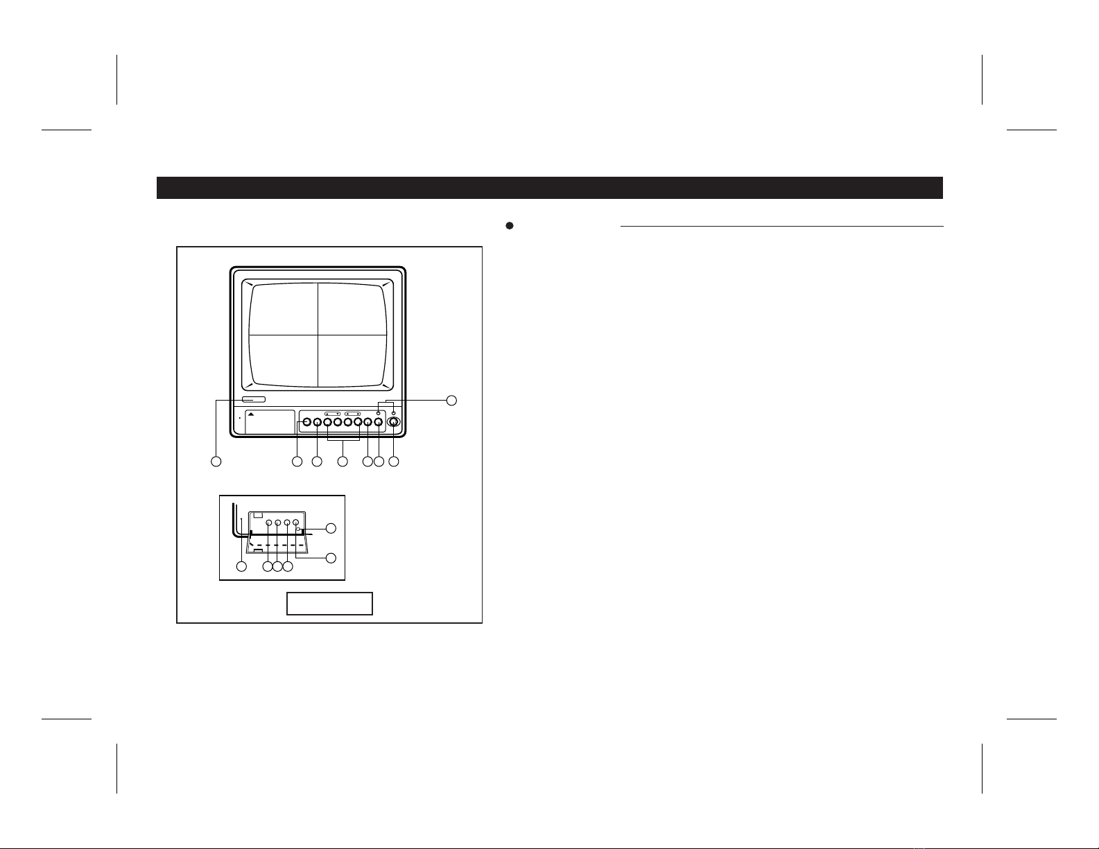
DESCRIPTION OF CONTROLS & OPERATION
5
( MAIN MENU )
1. TITLE SET
2. SEQUENCE
3. SCAN DWELL TIME
4. ALARM RESET TIME
5. TIME DATE
6. EXIT