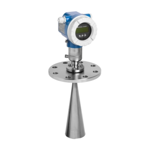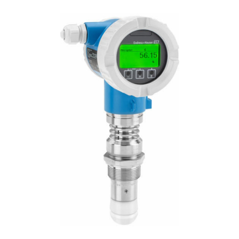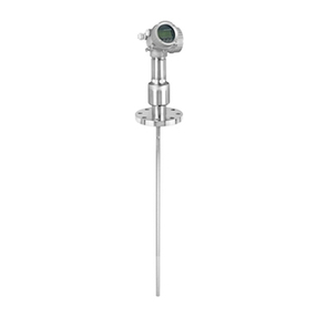
Micropilot FMR60/62/67
Endress+Hauser 9
Safety function
Definition of the safety
function
The device's safety functions are:
Safety function (level measurement)
• Maximum point level monitoring (overfill protection)
• Minimum point level monitoring (dry run protection)
• Level range monitoring
The safety functions include level measurement of a liquid or bulk solid.
Safety-related signal The safety-related signal is the analog output signal: 4 to 20 mA. All safety measures refer to this
signal exclusively.
For devices with current output and switch output (ordering feature 020 "Power Supply; Output",
option B "2-wire; 4-20 mA HART, switch output"), only the current output (terminals 1 and 2) is
approved for safety functions. The switch output (terminals 3 and 4) can, if necessary, be wired for
non-safety-oriented purposes.
For devices with two current outputs (ordering feature 020 "Power Supply; Output", option C "2-wire;
4-20 mA HART + 4-20 mA analog"), only the first current output (terminals 1 and 2) is approved for
safety functions. The second output (terminals 3 and 4) can, if necessary, be wired for non-safety-
oriented purposes.
The device additionally communicates for information only via HART and contains all HART features
with additional device information.
The safety-related output signal is fed to a downstream logic unit, e.g. a programmable logic
controller or a limit signal transmitter where it is monitored for the following:
• Exceed and/or undershoot a specific level limit.
• The occurrence of a fault, e.g. error current (≤3.6 mA, ≥21.0 mA, interruption or short-circuit of
the signal line).
In case of fault it must be ensured that the equipment under control achieves or maintains a
safe state.
Restrictions for use in safety-
related applications
• The measuring system must be used correctly for the specific application, taken into account the
medium properties and ambient conditions. Carefully follow instructions pertaining to critical
process situations and installation conditions from the Operating Instructions. The application-
specific limits must be observed.
• Information on the safety-related signal, (→ 9).
• The specifications from the Operating Instructions must not be exceeded, (→ 7).
• The following restrictions also applies to safety-related use:
– Strong, pulse-like EMC interference on the line can cause transient (< 1 s) deviations ≥ ±2% in
the output signal. For this reason, filtering with a time constant of ≥ 1 s should be performed in
the downstream logic unit.
– The error range is device specific and is defined according to FMEDA (Failure Modes, Effects and
Diagnostic Analysis) on delivery. It includes all influential factors described in the Technical
Information (e.g. non-linearity, non-repeatability, hysteresis, zero drift, temperature drift, EMC
influences).
According to IEC / EN 61508 the safety related failures are classified into different categories,
see the following table. The table shows the implications for the safety-related analog output
signal and for measuring uncertainty.
