Elan City EVOLIS User manual
Document REF:
MIU
-
5100
-
A_Evolis Solution GB elancity
Page
1
/
46
Date: 03/01/2018
Confidential document, property of ELANCITY. All copies and transfers are unauthorized without prior consent.
The EVOLIS RADAR SPEED SIGN
User Guide
ELAN CITY Ltd.
208 Blythe Road
London
W14 0HH
(020) 3936 0920

User Guide
Product: Evolis
Document REF:
MIU
-
5100
-
A_Evolis Solution GB elancity
Page
2
/
46
Date: 03/01/2018
Confidential document, property of ELANCITY. All copies and transfers are unauthorized without prior consent.
1 WARNING ................................................................................................................................................3
2 DELIVERY .................................................................................................................................................4
2.1 UNPACKING ............................................................................................................................................4
2.2 PACK CONTENTS.....................................................................................................................................4
3 PRODUCT DESCRIPTION ...........................................................................................................................6
4 TEST YOUR DEVICE BEFORE INSTALLATION ..............................................................................................7
4.1 AUTO-TEST ................................................................................................................................................7
4.2 DATE AND TIME SET-UP: ...............................................................................................................................8
4.3 TEST YOUR SETTINGS ....................................................................................................................................9
5 INSTALLATION ....................................................................................................................................... 11
5.2 FIX YOUR DEVICE SECURELY .................................................................................................................12
5.3 ALWAYS MAKE SAFETY A PRIORITY .................................................................................................................12
5.4 POWER SUPPLY .........................................................................................................................................13
5.4.1 The Mains or Street Lighting Model: ..............................................................................................14
5.4.2 The Solar power Model: ..................................................................................................................15
5.4.3 The Battery operated - Mains Mobile Model: .................................................................................15
6 MANAGING YOUR EVOLIS RADAR SPEED SIGN ...................................................................................... 16
6.1 ICONS .....................................................................................................................................................19
6.2 THREE-COLOUR DISPLAY : ...........................................................................................................................19
6.3 SCHOOL-ZONE MODE (‘TIME SLOT DISPLAY MODE’): .........................................................................................20
6.4 WARNING TRIANGLE DISPLAY .......................................................................................................................21
6.5 MESSAGE DISPLAY .....................................................................................................................................22
6.6 PARAMETERS FOR ADVANCED STATISTICS MANAGEMENT FEATURES .....................................................................25
6.7 DOWNLOADING DATA FROM THE EVOLIS TO A COMPUTER .................................................................................26
6.8 SUMMARY PAGE .......................................................................................................................................27
7 DATA ANALYSIS: .................................................................................................................................... 29
7.1 GRAPHIC VISUALIZATION: ...........................................................................................................................29
7.2 AVERAGE SPEED ........................................................................................................................................31
7.3 PERCENTILES ............................................................................................................................................35
7.4 OTHER EVOGRAPH FEATURES ..............................................................................................................36
7.5 CONNECTING YOUR COMPUTER TO THE EVOLIS VIA BLUETOOTH ..........................................................................37
8 MISCELLANEOUS .................................................................................................................................... 40
9 TECHNICAL SPECIFICATIONS:.................................................................................................................. 40
10 IF THE EVOLIS DOESN’T WORK : ............................................................................................................. 42
11 CUSTOMER SERVICE – TERMS AND CONDITIONS GUARANTEE............................................................... 43
11.1 WARRANTY .............................................................................................................................................44
11.2 SPARE PARTS ........................................................................................................................................46
11.3 USER MANUALS / SOFTWARE ..............................................................................................................46

User Guide
Product: Evolis
Document REF:
MIU
-
5100
-
A_Evolis Solution GB elancity
Page
3
/
46
Date: 03/01/2018
Confidential document, property of ELANCITY. All copies and transfers are unauthorized without prior consent.
1 WARNING
This equipment generates, uses and can radiate radio
frequency energy and, if not installed and used in accordance
with the instructions, may cause interference to radio
communications.
If this equipment does cause interference to radio or television
reception, (which can be determined by turning the Evolis off
and on), the user is encouraged to try to correct the interference
by one or more of the following measures:
- Reorient or relocate the receiving antenna.
- Increase the separation between the equipment and
receiver.
- Connect the equipment into an outlet on a circuit
different from that to which the receiver is connected.
- Consult the dealer or an experienced radio/TV
technician for help.
R
F Emission
Warning: The Evolis contains radio-frequency transceivers and
antennas which emit and receive in the 24GHz frequency band.
It can interfere with, and its functionality can be impacted by,
other nearby equipment operating in the same frequency band.
RF Exposure
Warning: Exposure to Radio Frequency Energy: The radiated
power output of the radar module is below the RF exposure
limits. This device should be operated with a minimum distance
of at least 20 cm between the antenna and a person’s body.
Elan City Company notices
The information within in this document can be changed without notice. All rights are reserved.
Reproduction, adaptation, or translation of this material is prohibited without prior written
permission from Elan City except as allowed under copyright law.
Elan City shall not be liable for technical or editorial errors or omissions contained in the
document.
Please note that the associated software (Evocom & Evograph) is continually being developed
and we advise you to update your version on a regular basis via the Customer Zone section
of our website www.elancity.co.uk.

User Guide
Product: Evolis
Document REF:
MIU
-
5100
-
A_Evolis Solution GB elancity
Page
4
/
46
Date: 03/01/2018
Confidential document, property of ELANCITY. All copies and transfers are unauthorized without prior consent.
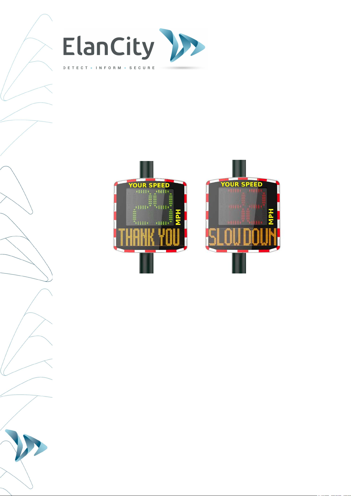
Thank you for choosing the EVOLIS Radar Speed Sign!
The EVOLIS Radar Speed Sign is a highly powerful yet budget-friendly traffic-calming tool.
Ideal for both rural and urban environments, this pole-mounted radar is visible at 300 yards
thanks to its ultra-bright, triple-colour, LED speed digits and its simultaneous display of
programmable messages.
Its traffic data collection function will function for both oncoming/outgoing traffic flows & the
pack includes the analysis software you’ll need.
The Evolis Radar Speed Sign‘s lightweight design and choice of full power-autonomy or
battery-powered options, means that its installation is easily within the scope of 1 person.
Constructed from highly durable UV resistant ABS injected Resin, this robust yet aesthetic
product can be trusted to operate in the most hostile weather conditions. With over 11,000
units installed worldwide, the Evolis Radar Speed Sign has become a global favorite!
In this user-guide, you’ll learn how to install, start-up, communicate with and if desired, re-
configure your Evolis radar so as to match your project’s specific needs and conditions!
2 DELIVERY
2.1 UNPACKING
RETAIN ALL THE ORIGINAL PACKING MATERIALS!
Elan City radars are covered by a 2 year parts & labour warranty. In the eventuality
that your device requires a workshop diagnosis or repair, the ORIGINAL packaging
MUST be used for the return transport to Elancity.
Not doing so may invalidate the warranty.
If you have discarded the original packaging will need to purchase replacement
packaging from Elan City before we can arrange for the factory return. Please
review the Warranty for more details.
Upon delivery, please verify that the contents noted on the packing list correspond with those
delivered. If you believe that there is some form of anomaly or that the goods have been
damaged you MUST make Elan City aware within 2 working days from the date of delivery.
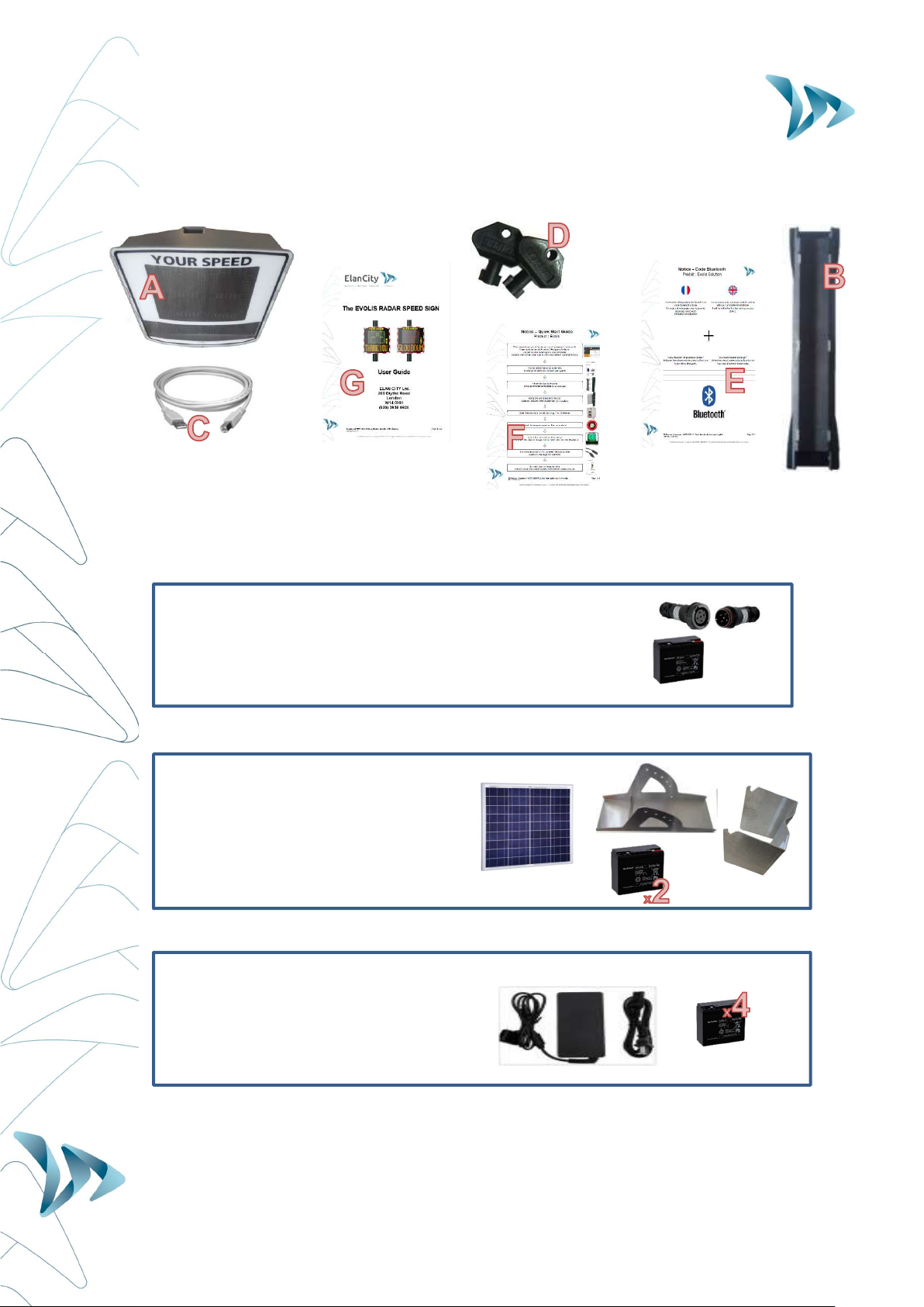
2.2 PACK CONTENTS
EVERY Evolis Pack (Mains/Street Light, Solar or Mains Mobile) will contain:
A) 1 x EVOLIS Radar Speed Sign
B) 1 x Vertical mounting bar
C) 1 x USB cable (15ft)
D) 2 x keys for the battery compartment
E) 1 x Bluetooth code
F) 1 x Quick-Start Guide
G) …As well as this user guide
User Guide
Product: Evolis
Document REF:
MIU
-
5100
-
A_Evolis Solution GB elancity
Page
5
/
46
Date: 03/01/2018
Confidential document, property of ELANCITY. All copies and transfers are unauthorized without prior consent.
Over & above the items listed above and dependent on the type of pack purchased, you will
find a number of additional items:
MAINS Pack (Street-lighting or Mains): Additional Items
Waterproof plugs for outdoor use (1 x male, 1 x female)
1 X battery (12V/22AH)
SOLAR Pack: Additional Items
1 x Solar panel
1 x Solar panel mounting bracket
1 x orientation adaptor
2 x batteries (12V/22AH)
Mains MOBILE Pack (Battery Operated): Additional Items
- External charger (12V)
- 4 X batteries (12V/22AH)
Please note that the images above may differ slightly from actual the products.
Batteries, solar panel, solar panel mounting bracket, and external chargers are delivered in
separate packages to that of the radar sign.
User Guide
Product: Evolis
Document REF:
MIU
-
5100
-
A_Evolis Solution GB elancity
Page
6
/
46
Date: 03/01/2018
Confidential document, property of ELANCITY. All copies and transfers are unauthorized without prior consent.
Batteries are delivered with an 80% charge and are ready for use.
Please note that neither the pole/lamp post, nor the fixing straps (jubilee clips) are included in
the purchase pack.
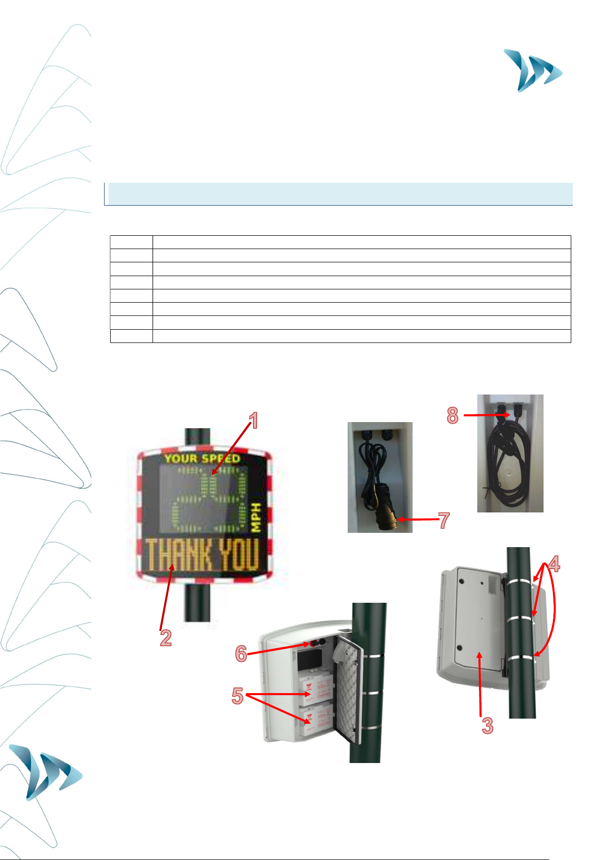
3 PRODUCT DESCRIPTION
1 LED speed display: green, red and amber
2 Message / graphic display (amber)
3 Access door to battery compartment, control dial, USB port and fuse
4 Fixing Collar/Jubilee Clips (not included)
5 Battery compartment (can hold up to 2 batteries)
6 Control dial; Waterproof USB port; Fuse for power supply
7 Electric plug for mains (Mains and Mains Mobile packs only)
8 Cables and plugs for solar panel connection (Solar packs only)

User Guide
Product: Evolis
Document REF:
MIU
-
5100
-
A_Evolis Solution GB elancity
Page
7
/
46
Date: 03/01/2018
Confidential document, property of ELANCITY. All copies and transfers are unauthorized without prior consent.
4 TEST YOUR DEVICE BEFORE INSTALLATION
We strongly recommend that you conduct an initial start-up & manipulation of your Evolis
device BEFORE installing it at the final desired location. In the unlikely event of a malfunction,
a telephone diagnosis (and also, in the worst case scenario, a factory return) is far simpler if
the unit is not already installed onto its post ‘in-situ’.
The very first step is to connect the battery.
4.1 AUTO-TEST
Once you have connected the battery, turn and set the dial switch to
any position OTHER than ‘off’ (standby).
The Evolis will run a quick auto-test (this is perfectly normal and there
is no need to intervene but it IS advisable to observe the display):
1 Speed display
‘
188
’
should be displayed in green and is
quite simply the device testing all the LEDs
in the display.
2 Speed display Then,
Three further numbers
will then be
displayed. These equate to the battery
voltage. (e.g. : ‘147’ = 14.7 Volts). A
normal reading will be situated between 11
and 13
Text display
‘
Init…
’
will then be displayed in the lower
part of the device
3 Speed display
‘
8
’
in red : signifies Bluetooth
‘1’ in green : signifies a GPRS connection
User Guide
Product: Evolis
Document REF:
MIU
-
5100
-
A_Evolis Solution GB elancity
Page
8
/
46
Date: 03/01/2018
Confidential document, property of ELANCITY. All copies and transfers are unauthorized without prior consent.
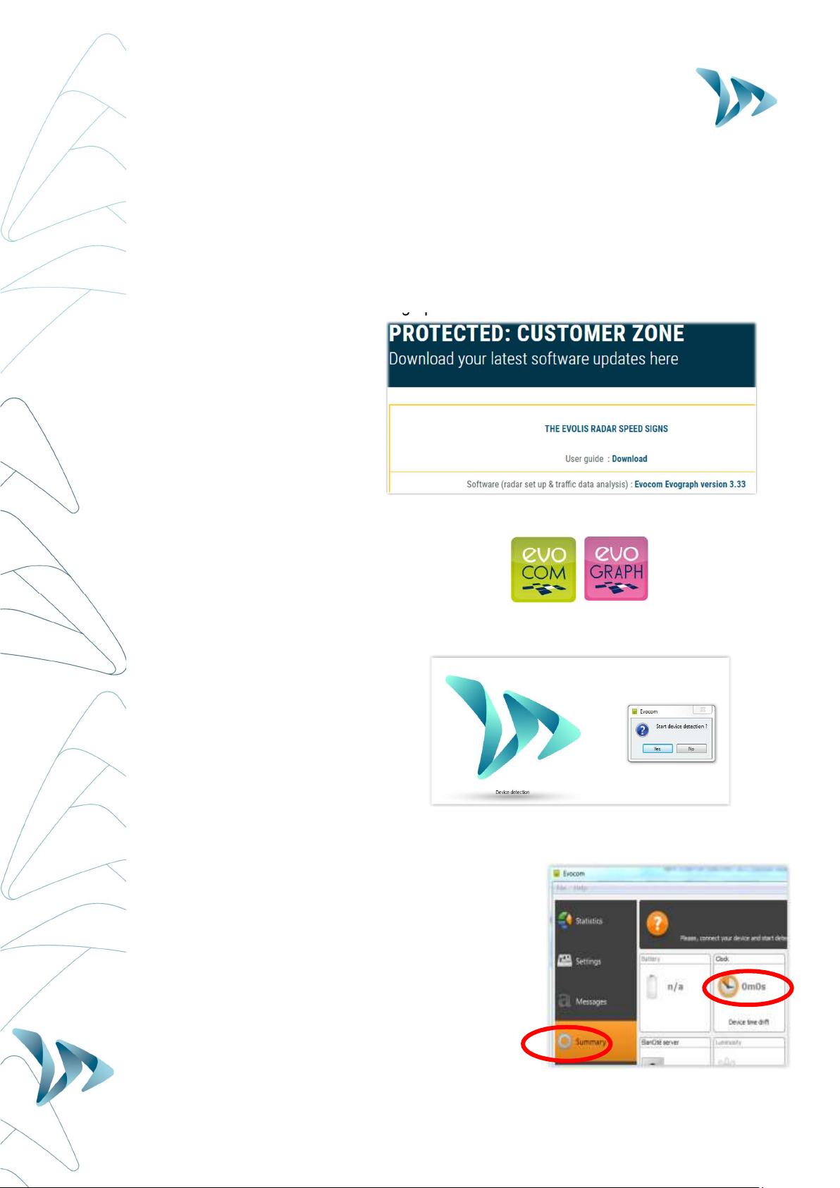
4.2 DATE AND TIME SET-UP:
The next step is to download the device software and then make the connection between the
software & the Evolis. All of our software programs are available for download through our
website.
Go to: www.elancity.co.uk and in the upper right hand corner click on “Customer Zone”
You’ll be asked for a password. The password required is "radarevolis.”
Download the Evocom – Evograph software.
Install using "Setup.exe".
Follow the instructions that will appear in the pop up dialogue boxes
Two shortcuts will appear on your desktop:
Connect the Evolis radar sign to your computer. (by USB cable or by Bluetooth)
Launch the EVOCOM software and it will propose an automatic detection of the device:
select “YES.”
Go to Summary / Clock: Update the Evolis internal clock to your local time. All you
need to do is click once on the clock symbol
(See section 6 for further details on installation
and advanced use of the software packages)

User Guide
Product: Evolis
Document REF:
MIU
-
5100
-
A_Evolis Solution GB elancity
Page
9
/
46
Date: 03/01/2018
Confidential document, property of ELANCITY. All copies and transfers are unauthorized without prior consent.
4.3 TEST YOUR SETTINGS
At this point (again, before the eventual installation ‘in-situ’) it is highly recommended to
perform a quick test run of your preferred settings.
For quick start-up, the radar’s parameters are pre-set with standard speed thresholds (based
on commonly used speed limits) and 3 pre-programmed messages (“THANK YOU”, “SLOW
DOWN” and “TOO FAST”).
These thresholds and messages can be re-programmed if desired.
The following thresholds/settings are pre-programmed but can be re-configured if desired:
Minimum speed display : to conserve power, the vehicle’s speed is only displayed if
it exceeds a certain threshold. This threshold is set at 9mph for all speed limit settings
Colour change threshold : the speed at which the Evolis display switches from
GREEN to RED)
Amber activation: The factory setting uses two colours for the speed display: green
and red. You can also add AMBER as an ‘intermediate’ colour if desired.
Maximum speed display : to eliminate any potential ‘race effect’, the speed display
will disappear if the recorded speed exceeds the limit by 12mph or more.
Message programming : You can program your own messages as well as the speed
thresholds at which they are activated. See the table below for the factory setting
messages as well as their activation thresholds.
Flash Threshold : The speed display is programmed to flash if the recorded speed
exceeds the limit by more than 5mph (factory setting ; can be modified)
The dial switch, in the battery compartment, allows you to easily select the speed according
to the local speed limit. This will automatically activate the pre-programmed thresholds
(Factory Settings). Please see the chart below for an outline view of the factory settings.
User Guide
Product: Evolis
Document REF:
MIU
-
5100
-
A_Evolis Solution GB elancity
Page
10
/
46
Date: 03/01/2018
Confidential document, property of ELANCITY. All copies and transfers are unauthorized without prior consent.
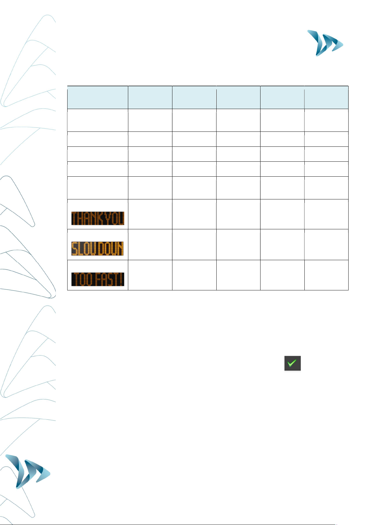
Factory Settings:
Dial
Switch
Position 20 mph 30 mph 50 mph 60 mph 70 mph
Minimum speed
displayed 9 mph 9 mph 9 mph 9 mph 9 mph
Color change 21 mph 31 mph 51 mph 61 mph 71 mph
Amber Zone * 2 mph 2 mph 2 mph 2 mph 2 mph
Flash threshold 26 mph 36 mph 56 mph 66 mph 76 mph
Maximum speed
displayed 31 mph 41 mph 61 mph 71 mph 81 mph
Message n°1
From 9 to
20 mph
From 9 to
30 mph
From 9 to
50 mph
From 9 to
60 mph
From 9 to
70 mph
Message n°2
From 21 to
30 mph
From 31 to
40 mph
From 51 to
60 mph
From 61 to
70 mph
From 71 to
80 mph
Message n°3
From 31
mph
From 41
mph
From 61
mph
From 71
mph
From 81
mph
Before looking at how to re-program your device (change the text messages, modify speed
thresholds etc…) later on in this manual, try this fairly simple manipulation that will allow
you to see how the Evolis works under the factory settings.
Set the dial to the desired speed limit setting (20, 30, 50, 60, or 70).
Then on the Evocom software, select the green tick symbol to launch a display that will
allow you to see your selected settings on the radar screen.
User Guide
Product: Evolis
Document REF:
MIU
-
5100
-
A_Evolis Solution GB elancity
Page
11
/
46
Date: 03/01/2018
Confidential document, property of ELANCITY. All copies and transfers are unauthorized without prior consent.
5 INSTALLATION
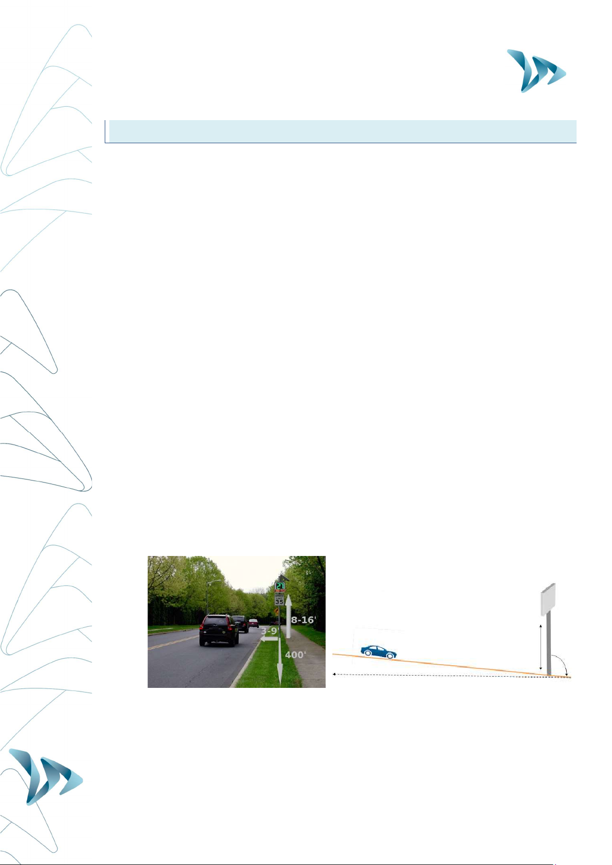
5.1 HOW BEST TO LOCATE YOUR RADAR SPEED SIGN
For optimal performance, select the radar's location according to the following criteria:
Choose a straight section road with at least 400ft of unobstructed vision.
This area and the radar beam should be free of any objects (trees, poles, parked
vehicles, other road signs…) as they may disturb the radar's beam.
Do not install radars at cross-roads, round-abouts or on bridges : vehicles arriving from
a sideways direction can have a confusing influence upon the radar sign's display and
the traffic data it captures.
Verify that the radar sign does not block the visibility of existing road signs.
Ensure that the bottom edge of the radar sign is no lower than 8ft and no higher than
16ft from ground level. (too low and there is a risk of collision with pedestrians)
To avoid accidental collision, ensure that you leave a gap of at least 3ft between the
radar screen and the road. We recommend a gap of between 3ft and 9ft.
The display screen should be positioned so that it points in a direction that is parallel
to the direction of the road. For example, if the screen is at the maximum distance of
9ft from the road, it should be positioned so as to point at an imaginary line that runs
parallel to the road at a distance of 9ft.
The sign must be installed straight (at 90°), unless there is a steep gradient (+/- 5°). In
this case, the sign should as far as is possible, be angled so that is matches the
gradient (using a wedge).
If you wish to install your Evolis on a gradient that exceeds 5%, please contact us.

User Guide
Product: Evolis
Document REF:
MIU
-
5100
-
A_Evolis Solution GB elancity
Page
12
/
46
Date: 03/01/2018
Confidential document, property of ELANCITY. All copies and transfers are unauthorized without prior consent.
5.2 FIX YOUR DEVICE SECURELY
Note: When moving, installing or de-installing the sign, always remove the batteries first.
This significantly reduces the weight of the device as well as the risk of stress related cracking.
.
For safety reasons, it is highly recommended to install the radar sign using a scissor lift or
small scaffolding.
1. Attach the (furnished) mounting-bar to the designated post/pole with the aid of fixing
collars/jubilee clips without overtightening them at this stage. Make sure the end that
is stamped ‘TOP’ does indeed get attached at the top.
1) Attach the main body of the radar sign (with batteries removed) by sliding the hooks of
the sign onto the mounting-bar.
2) Adjust the radar sign's position/height and then fully tighten the fixing collars.
3) The radar sign can be further secured to the mounting bar with the aid of a padlock
(padlock is not furnished but there is an ‘eye-hole’ built into the structure for this
purpose)
4) Install the batteries, and / or connect the sign with mains electricity or street lights.
For solar-powered radar signs, the first step is to install the solar panel to the
pole/lamp-post. (using the furnished solar mounting kit). Then procede to the
installation of the radar sign. (See the Solar-power user guide)
5.3 ALWAYS MAKE SAFETY A PRIORITY
- CHECK and COMPLY with current regulations concerning working at a height.
- CHECK and COMPLY with local regulations regarding traffic and road sign installation
- VERIFY that the designated pole is stable and has a sufficient diameter.
(Min. 3inch diameter for AC models, and min. 5inch diameter for Solar models).
If in doubt, consult our sales or customer service representatives.
- If your installation involves connections to mains electricity either directly or through
street lighting, ensure you CHECK and COMPLY with local regulations.
User Guide
Product: Evolis
Document REF:
MIU
-
5100
-
A_Evolis Solution GB elancity
Page
13
/
46
Date: 03/01/2018
Confidential document, property of ELANCITY. All copies and transfers are unauthorized without prior consent.
5.4 POWER SUPPLY
Power source:
The Evolis is 12V powered and designed to operate with either:
- Mains: A connection to a permanent mains network. OR to street lighting network in
combination with a battery (12V/22Ah).
- Solar: A solar panel and 2 batteries (12V22Ah).
- Mains Mobile: Battery operated (12V22Ah). Pack includes 4 batteries in total and an
external 12V/4A charger. NOTE: the casing can hold two batteries at one time.
Power consumption:
Thanks to its low power consumption, the battery charging cycle guarantees an extended
duration of operation. Average consumption and wattage as follows:
- Speed: 0.3 A (3.6 Watts at 12V).
- Speed + Message: 0.8 A (9.6 Watts at 12V).
- Standby: 0.1 A (1.2 Watts at 12V).
Power safety / security:
If and when the Evolis radar runs out of power, it has a built-in safeguard that is based on
various thresholds of the battery voltage.
- At 11.5V: The message display wil be de-activated
- At 11.3V: The speed display will be deactivated. The radar will display a small square
to indicate that the speed display is off. NOTE: the radar will still continue to collect
traffic data.
- At 11.1V: The radar will shut down in order to avoid damaging to the battery
Electrical fuse:
To protect the device in case of reversed polarity, a 6.3A fuse is located within the casing.

User Guide
Product: Evolis
Document REF:
MIU
-
5100
-
A_Evolis Solution GB elancity
Page
14
/
46
Date: 03/01/2018
Confidential document, property of ELANCITY. All copies and transfers are unauthorized without prior consent.
5.4.1 The Mains or Street Lighting Model:
For power through the permanent mains network or the street lighting system, the Evolis is
supplied with:
- A 4Ah transformer
- A 12V / 22Ah battery
- IP66 male plug pre-cabled into the Evolis
- IP66 female plug for connection to the mains electricity supply
Connect the FEMALE plug to the mains electricity supply:
- Wire the neutral wire (commonly blue colour) cable on the "N"
- Wire the live wire (commonly brown colour) on the "1"
- Wire the earth wire (commonly green/yellow) on the CENTRE connection
- The other two prongs in the plugs are not used
- Then, simply plug the Evolis into the mains by plugging the male plug into the female.
The plugs are equipped with a twist mechanism that not only renders them waterproof but
also prevents them from being pulled apart. Don’t forget to activate this final twist before use.
The only difference between the permanent mains and the mains street lighting schema is that
the street light system requires the addition of a battery whereas the permanent mains system
does not (apart from instances where there is a localised power cut) .
Under the street lighting system,the Evolis will still function without a battery but ONLY during
the hours that the street lighting is functioning. With a battery added, it will charge during street
lighting hours and then take over as a power source from the street lighting as soon as daylight
hours dictate that they are switched off.
We strongly recommend adding a 30mA calibre 16A type AC circuit breaker
between the mains current & the radar speed sign. ELANCITY cannot be held
responsible for damages caused by a poor quality installation. In the absence of
a circuit breaker and the subsequent failure of the internal electrical charger, the
warranty will be invalidated.

User Guide
Product: Evolis
Document REF:
MIU
-
5100
-
A_Evolis Solution GB elancity
Page
15
/
46
Date: 03/01/2018
Confidential document, property of ELANCITY. All copies and transfers are unauthorized without prior consent.
5.4.2 The Solar power Model:
Ideally, the solar panel should be positioned in a south facing direction and then
secured with a padlock attached through the ‘eyehole’ at the bottom (padlock not
included). The solar panel’s mounting bracket can be adjusted to the desired vertical
angle.
Make sure you have fitted and connected the batteries inside the Evolis BEFORE
making the connection between the solar panel and the radar sign.
To connect the Radar Sign to the Solar Panel you simply plug the 2 cables from the radar into
the panel.
Mounting: please refer to the solar-panel user guide.
The solar panel’s location must have, as far as possible, an unobstructed view of the sky to
benefit from maximum charging capacity. Trees and buildings can cast shadows on to the
solar panel which can considerably reduce the performance of the solar cells.
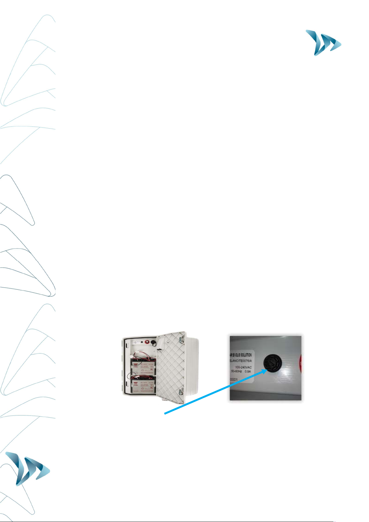
5.4.3 The Battery operated - Mains Mobile Model:
Battery operated using two batteries:
In the case of mobile use (i.e. where the device is intended to be moved from place to place),
the Evolis is designed to function using either one or two sealed, 12V / 22Ah batteries. After
opening the back door of the unit, install the charged batteries into the slot between the two
retaining hooks.
Check the polarity orientation and connect to the terminals.
Turn the dial switch to select your speed.
Check the auto startup display on the Evolis (auto-test: ‘188’ / battery voltage / ‘8’ in
red for Bluetooth version).
25°
-
65°

User Guide
Product: Evolis
Document REF:
MIU
-
5100
-
A_Evolis Solution GB elancity
Page
16
/
46
Date: 03/01/2018
Confidential document, property of ELANCITY. All copies and transfers are unauthorized without prior consent.
Power autonomy – One sole battery will generally provide sufficient power for 3 to 8 days
dependent on traffic flow. The radar will indicate low-battery by showing a tri-colored square
on the bottom right corner of the speed display. When you see this display (or before), the
batteries should be replaced with the two charged batteries.
Elan City batteries discharged to 11.1V require approximately 5 hours to charge. The charging
time may vary depending on the remaining battery charge and the conditions under which the
charge is made. The batteries can be charged at any time (i.e. there is no requirement to wait
until it is ‘flat’.
Battery charger light RED Signifies the start of the charge
Battery charger light ORANGE Signifies that charging is underway
Battery charger light GREEN Signifies that the battery is fully charged
A charged battery will gradually discharge even when not in use. Remember to
charge the battery before use using the provided battery charger.
Remember to remove the batteries before moving, installing or de-installing the radar
sign. Removing the batteries significantly reduces the weight of the device as well as
the risk of stress related cracking.
Use of batteries, chargers or other accessories not provided by Elan City will
invalidate the Warranty.
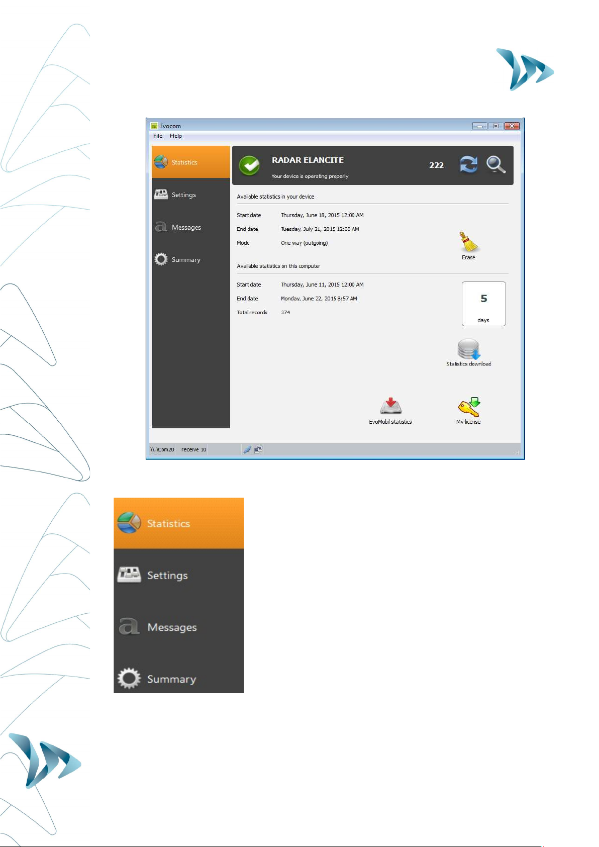
6 MANAGING YOUR EVOLIS RADAR SPEED SIGN
Evocom : The Evocom software allows you to set-up and program your radar sign.
Above, in section 4.2 you’ll have seen how to install the software and effect your first test.
When you open Evocom, the default opening page will display a summary of the available
statistics.
User Guide
Product: Evolis
Document REF:
MIU
-
5100
-
A_Evolis Solution GB elancity
Page
17
/
46
Date: 03/01/2018
Confidential document, property of ELANCITY. All copies and transfers are unauthorized without prior consent.
→ Home page, your statistics and the connection to the
Smartphone app, Evomobile.
→ Where you can over-ride the factory settings and program
the radar with your own settings. For this, the dial switch
inside the Evolis must be at the "SP " setting. Only the
‘Statistics’ & ‘Spy Mode’ will function with the dial switch at
any other setting.
→ Message and graphics programming
→ Summary page, the technical information about your radar

User Guide
Product: Evolis
Document REF:
MIU
-
5100
-
A_Evolis Solution GB elancity
Page
18
/
46
Date: 03/01/2018
Confidential document, property of ELANCITY. All copies and transfers are unauthorized without prior consent.
SETTINGS PAGE:
All of the programmable controls and thresholds are displayed on the “SETTINGS” page. The
displayed settings are those currently in the Evolis radar’s memory. To program or modify
these thresholds; select the desired setting(s), and then validate your choice by clicking the
blue arrow icon, which will send this information to the Evolis radar’s memory.
The message "Device configuration done" indicates that the set-up was completed correctly.
To save your new configuration for use at a later date, click the save icon:
‘SP’ : Remember, in order to modify the settings/thresholds via the ‘SETTINGS’ page, the
control dial inside the case of the device must be set to ‘SP’. If the control dial is set to any
other setting, 70mph for example, then the settings you see on this page are NOT active.
Only speed settings can be saved for use as a future configuration. Re-
configured text messages cannot be saved.
User Guide
Product: Evolis
Document REF:
MIU
-
5100
-
A_Evolis Solution GB elancity
Page
19
/
46
Date: 03/01/2018
Confidential document, property of ELANCITY. All copies and transfers are unauthorized without prior consent.
SPY MODE:
This option allows the radar to continue collecting traffic data as usual, but the motorist will
only see a blank radar screen. This allows you to test the radar’s efficiency by comparing the
traffic statistics recorded when the radar is ON against those when it is (seemingly) OFF.
STATISTICS:
Allows you to enable/disable the two-way traffic data recording.
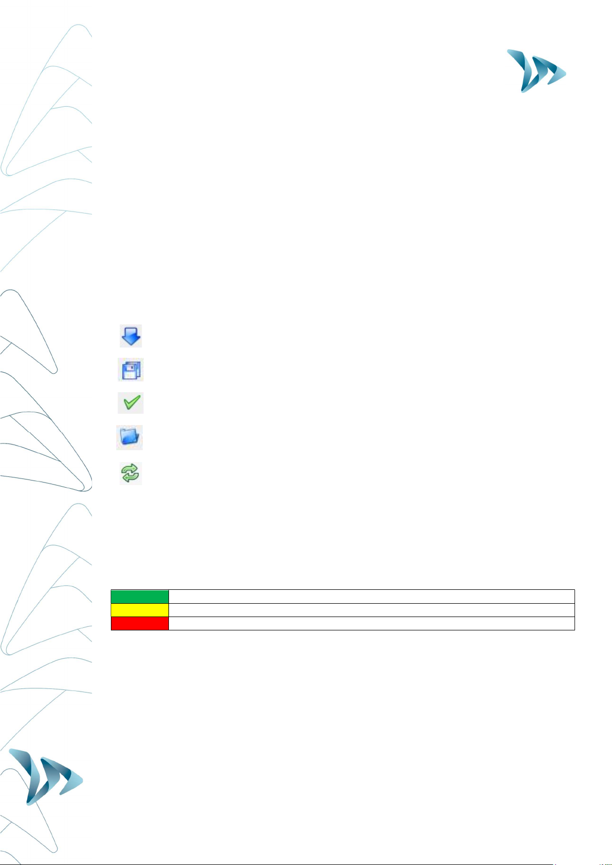
6.1 ICONS
SEND the new settings to the Evolis radar.
SAVE the setting for future use (speed settings only)
SEE your new settings displayed on the Evolis radar screen
OPEN a previously saved setting
RELOAD the parameters of a previously recorded setting into the Evolis radar
6.2 THREE-COLOUR DISPLAY :
The Evolis radar can display up to 3 colours: (Note : The factory setting uses two colours
only for the speed display: green and red.).
GREEN for speeds
below
the speed limit
AMBER for speeds
close to
the speed limit
RED for speeds
above
the speed limit
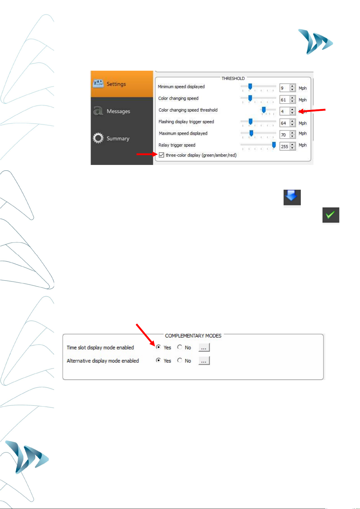
* Amber activation: To activate additional amber colour follow the directions below:
Ensure the control dial is set to ‘SP’
Go to Settings, select the check box “three-color display (green/amber/red).”
User Guide
Product: Evolis
Document REF:
MIU
-
5100
-
A_Evolis Solution GB elancity
Page
20
/
46
Date: 03/01/2018
Confidential document, property of ELANCITY. All copies and transfers are unauthorized without prior consent.
Then set the margins within which you wish the display in Amber in the ‘Colour
changing Speed Threshold’. i.e. in the example above, at 4mph before the display will
turn to RED.
Upload the new settings to the device by clicking the blue arrow.
Select the green tick to launch a display that will preview your selected settings.
6.3 SCHOOL-ZONE MODE (‘TIME SLOT DISPLAY MODE’):
The radar can be configured to switch between two different settings – Ideal for school zones!
This can be done through the Evocom software in the section “time slot display mode.” The
radar will automatically switch the speed threshold and messages / graphics at a certain time
of day. For example, the radar can be configured to feature a lower speed limit when school
is out and children are present, AND display a special message such as: « CAUTION
SCHOOL »
- Ensure the control dial is set to ‘SP’
- Go to Complementary modes
- Select “yes” for the “time slot display mode enabled”
By selecting « Yes », the following window will appear:
This manual suits for next models
1
Table of contents
Other Elan City Radar manuals

Popular Radar manuals by other brands

Endress+Hauser
Endress+Hauser Micropilot FMR63B Brief operating instructions

Endress+Hauser
Endress+Hauser Levelflex FMP53 PROFIBUS PA Brief operating instructions

GE
GE RCR-PET installation instructions

Cobra
Cobra 15 BAND ULTRA XRS 9845 operating instructions

AGD
AGD 318 product manual

Endress+Hauser
Endress+Hauser Micropilot FMR60 Functional safety manual

Blackbe;rry
Blackbe;rry Radar R2 installation guide

TERMA
TERMA SCANTER 5102 Technical maintenance manual

Escort
Escort MAX Ci 360 owner's manual

Traffic Logix
Traffic Logix SafePace 700 installation manual

Nobeltec
Nobeltec IR2-HD2 Installer's guide

Endress+Hauser
Endress+Hauser Levelflex FMP55 operating instructions


