©2007 ELAN Home Systems • All Rights Reserved 1
¸
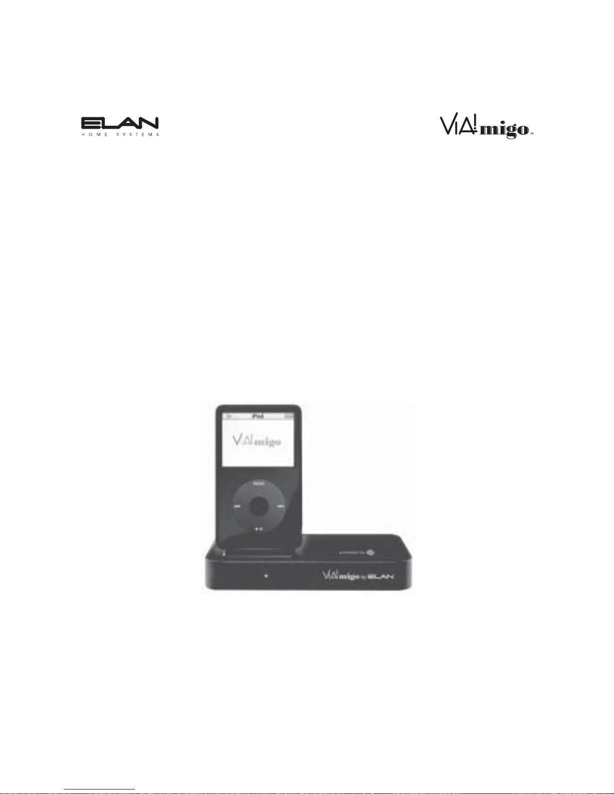
Contents
Introduction ........................................................................................ 3
Features & Specifications...................................................................... 4
Features ............................................................................................ 4
Specifications ................................................................................... 7
Getting Started ................................................................................ 8
Connections ........................................................................................... 9
Connecting the VIA!migo to a Home Stereo or A/V Receiver........ 10
Control Connections ........................................................................ 11
Connecting VIA!migo to an ELAN Multi-Room Controller.............. 14
Connecting To Your A/V System...................................................... 20
Connecting Your iPod ...................................................................... 21
Adjusting VIA!migo to Fit Your iPod ................................................ 21
Operation.............................................................................................. 23
VIA!migo Modes..................................................................................... 23
Dock Mode (On-Screen Navigation)................................................ 23
iPod Mode ........................................................................................ 25
Basic On-Screen Display Navigation.................................................... 26
On-Screen Display Navigation Page Layout................................... 27
On-Screen Navigation Tips & Tricks ..................................................... 30
Shuffle Functions.............................................................................. 30
Speed-Scroll Functions.................................................................... 30
Screen Savers................................................................................... 31
Playing & Controlling Music .................................................................. 32
Tips & Tricks For Playing Music ...................................................... 32
How to Switch Between NTSC and PAL .............................................. 33