Elan Z-025 User manual

025
SPEAKER RELAY/
AUDIO DETECT
SWITCHING
MODULE
INSTALLATION
MANUAL
P/N: 40615-121-03

©Copyright 1999 ELAN Home Systems, LLC. ELAN, ELAN Home Systems, Z•025 Z•026, Z•080, Z•090, Z•630, Z•100, Z•150, Z•PAD, Series HD™ are
registeredtrademarks of ELAN Home Systems, 2428 Palumbo Drive, Lexington, KY 40509. Elan reserves the right to change product specifications
without notice.
ELAN HOME SYSTEMS INSTALLATION MANUAL
© ELAN Home Systems • 2003 • All rights reserved. 2/03 page 2
025
TABLE OF CONTENTS
INTRODUCTION . . . . . . . . . . . . . . . . . . . . . . . . . . . . . . . . . . . . .3
SETTINGS AND ADJUSTMENTS . . . . . . . . . . . . . . . . . . . . .4
MOUNTING THE Z•025 to the Z•100 . . . . . . . . . . . . . . . . . .5
MOUNTING THE Z•025 to the Z•250 . . . . . . . . . . . . . . . . . .6
CONNECTIONS . . . . . . . . . . . . . . . . . . . . . . . . . . . . . . . . . . .7-12
Connecting Z•025s to the Z•630 PreAmp Controller . .6-7
Conntecting Z•025s to the Series HD™ MCU . . . . . . .8-9
Connecting Z•025s to the Z•080 Stand-Alone
Keypad Interface . . . . . . . . . . . . . . . . . . . . . . . . . .10
Adding a Dedicated TV Amplifier . . . . . . . . . . . . . . . . .11
Connecting the Z•600 Comm Controler’s Page &
Doorbell Override Signal . . . . . . . . . . . . . . . . . . . .12
APPLICATIONS . . . . . . . . . . . . . . . . . . . . . . . . . . . . . . . . . .13-15
Zone/Sub-Zone (Scenario 1) . . . . . . . . . . . . . . . . . . . .13
Zone/Sub-Zone (Scenario 2) . . . . . . . . . . . . . . . . . . . .14
Zone/Sub-Zone (Scenario 3) . . . . . . . . . . . . . . . . . . . .15
Limited Warranty
ELAN HOME SYSTEMS, L.L.C. (“ELAN”) warrants the Z•025 Speaker Relay/Audio Detect Switching Module manufactured by it to be free from defects in materials and workmanship for
two (2) years from the date of purchase. If within the applicable warranty period above purchaser discovers such item was not as warranted above and promptly notifies ELAN in writing,
ELAN shall repair or replace the items at the company’s option. This warranty shall not apply (a) to equipment not manufactured by ELAN, (b) to equipment found to have been installed
by other than an authorized ELAN installer, (c) to installed equipment which is not installed to ELAN’s specifications, (d) to equipment found to have been repaired or altered by others than
ELAN, (e) to equipment found to have been subjected to negligence, accident, or damage by circumstances beyond ELAN’s control, including, but not limited to, lightning, flood, electrical
surge, tornado,
earthquake, or any other catastrophic events beyond ELAN’s control, or to improper operation, maintenance or storage, or to other than normal use of service. With respect to equipment
sold by, but not manufactured by ELAN, the warranty obligations of ELAN shall in all respects conform and be limited to the warranty actually extended to ELAN by its supplier. The fore-
going warranties do not cover reimbursement for labor, transportation, removal, installation, or other expenses which may be incurred in connection with repair or replacement.
Except as may be expressly provided and authorized in writing by ELAN, ELAN shall not be subject to any other obligations or liabilities whatsoever with respect to equipment manufac-
tured by ELAN or services rendered by ELAN.
THE FOREGOING WARRANTIES ARE EXCLUSIVE AND IN LIEU OF ALL OTHER EXPRESSED AND IMPLIED WARRANTIES EXCEPT WARRANTIES OF TITLE, INCLUDING BUT
025
SPEAKER RELAY/
AUDIO DETECT
SWITCHING MODULE
2428 Palumbo Drive • Lexington, KY 40509 • 1.859.269.7760 • FAX 1.859.269.7972

© ELAN Home Systems • 2003 • All rights reserved. 2/03 Page 3
ELAN HOME SYSTEMS INSTALLATION MANUAL
025
INTRODUCTION:
025
The Z•025 is a multi-purpose module that plugs right onto the back of a Z•100
keypad. The Z•025 can be easily configured to:
• Automatically switch between the System Audio and Local Source
Audio in any room.
• Manually switch between System Audio and Local Source Audio in any
room.
• Mute the speakers in one room of a zone without muting other rooms/
speakers in that zone.
When designing a System, it is
important to decide which
room(s) or zone(s) will have
Z•025’s in them as these areas
will be wired differently than
rooms without Z•025’s.
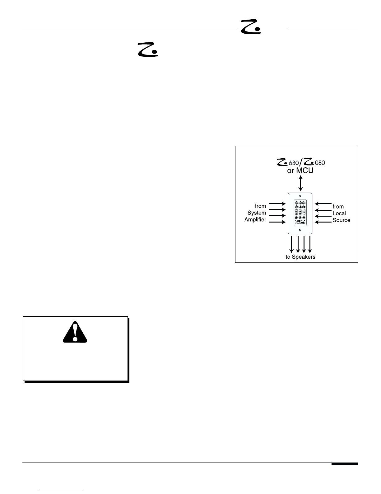
In rooms/zones without Z•025’s,
speaker and/or volume control
wire runs are pulled directly back
to the amplifier. In rooms/zones
with Z•025’s, all audio wire runs
are pulled to the keypad location
first before being routed to the
speakers.
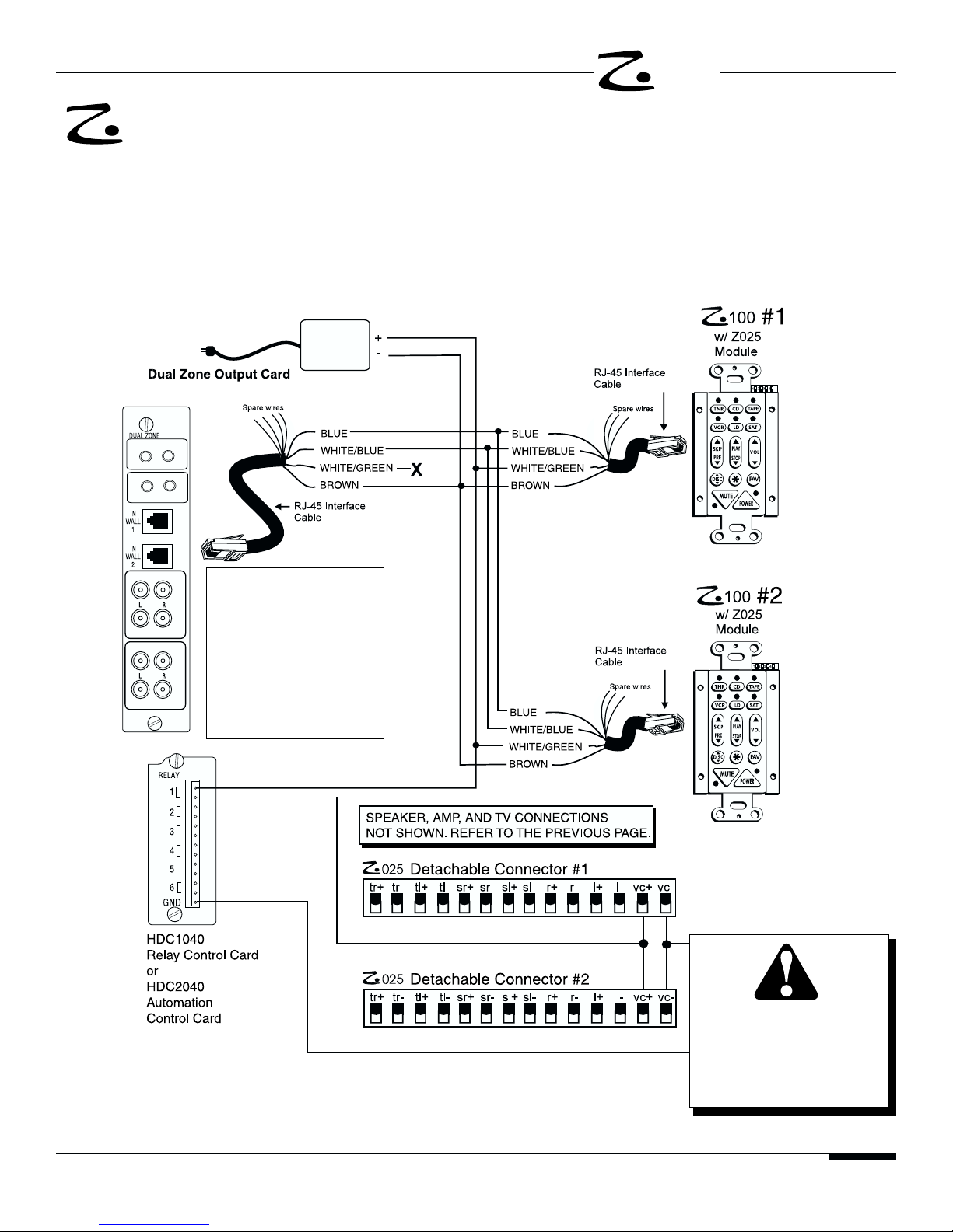
The Z•025 combines audio
detect circuitry and low-voltage
relays to perform its various functions. Dip switches located on the back of the
Z•025 determine the “mode” it is in.
• When in TV Detect Mode, the Z•025 will “detect” speaker-level audio from a
local source (i.e. TV) and automatically route the signal from the TV to the
speakers when the TV is turned on. Turning OFF the TV (or selecting anoth-
er source) will automatically re-route the speakers back to the ELAN system.
The Z•025 will also automatically switch back to the ELAN system whenever
a Page or Door Chime is detected, then revert back to the local source when
the Page or Door Chime has ended. For this feature, the Page and Door
Chime override signal from a Z•600 Comm Controller must also be routed to
the Z•025 (see Page 12).
The TV Detect feature can be overridden, enabling the user to manually
switch between System Audio and local TV Audio simply by selecting “TV”
from the ELAN Z•150/250 Keypad or System Audio from any ZPAD. Once
again, the relays on the Z•025 will automatically switch the speakers back to
System Audio for the duration of a Z•600 Page or Door Chime signal, then
revert back to TV Audio.
• The Z•025 also allows you to mute the speakers in one room of a zone inde-
pendently of other speakers in that zone, OR turn on the speakers in one
room without turning on the speakers in another room of the same zone.
MUTE MODE is used when a zone is comprised of more than one room (i.e.
Master Bedroom/Master Bath). This enables the user to wake up in the
morning, go into the Master Bath and turn on the music in the Bath without it
coming on Master Bedroom, even though it is part of the same zone.
System6
DO NOT OVERTIGHTEN MOUNT-
ING SCREWS––HAND TIGHTEN
ONLY.
Z•100 Keypads must be downloaded
to by a Z•090 Keypad Programming
Module before the Z•025 Switching
Module will function.
SPEAKER RELAY/AUDIO
DETECT SWITCHING MODULE

ELAN HOME SYSTEMS INSTALLATION MANUAL
© ELAN Home Systems • 2003 • All rights reserved. 2/03 Page 4
025
SETTINGS AND ADJUSTMENTS
025
DDiippSSwwiittcchhSSeettttiinnggss
MUTE RRELAY DDISABLED
When the MUTE dip switch is in the OFF position, pressing the
MUTE key on the Z•100/250 will mute the source audio in a zone via
an IR command. If using only one keypad in a zone, this switch can
be kept in the OFF position.
MUTE RRELAY EENABLED
When the MUTE dip switch is in the ON position, pressing the MUTE
key on the Z•100/250 will mute the speakers connected to the Z•025
via the mute relay instead of sending a Mute IR command.
TV DDETECT OON
In this mode the automatic signal
detect feature is active. The Z•025 will automatically switch from
System Audio to TV Audio when the TV is turned on and back to
System Audio when the TV is turned off or another source is select-
ed.
TV DDETECT OOFF
In this mode the automatic signal detect feature is bypassed. To
switch from System Audio to TV Audio, you must manually select TV
at the Z•150/250 keypad.
PPootteennttiioommeetteerrSSeettttiinnggss
THRESHOLD ((P2)
When the Z•025 is in the TV DETECT mode (see above), the
THRESHOLD adjustment sets the level at which the Z•025 will
detect TV Audio and automatically switch the speakers from System
Audio to TV Audio.
THRESHOLD sensitivity can be adjusted from <10mV RMS to >1.1 V RMS
Threshold adjustments should be made before adjusting the HOLD pot.
HOLD ((P1)
When the Z•025 is in the TV detect mode (see above), the HOLD
adjustment is used to set the amount of time the Z•025 will wait before
switching back to System Audio once TV Audio has been turned off.
HOLD time can be adjusted between 3 to 60 seconds.
(Dip Switch to the left––
Factory Default)
(Dip Switch to the right)
(Dip Switch to the left––
Factory Default)
(Dip Switch to the right)

© ELAN Home Systems • 2003 • All rights reserved. 2/03 Page 5
ELAN HOME SYSTEMS INSTALLATION MANUAL
025
DO NOT OVERTIGHTEN MOUNT-
ING SCREWS––HAND TIGHTEN
ONLY.
DO NOT MACHINE TIGHTEN.
OVERTIGHTENING MAY CAUSE
SHORT
SPACERS
SHORT
SPACER
ADD
LONG
SPACERS
ADD
LONG SPACER
LONG
MOUNTING
SCREWS
MOUNTING THE TO THE
025
INSTALLATION TIP:
OVERTIGHENING CAN CAUSE
KEYPADS TO STICK
After mounting the Z•025, it is important
to check that all the keycaps are making
proper contact with the switches below
them. If not, loosen the Z•025 mounting
screws 1/4 turn until all keycaps move
freely.
1. Remove the detachable 14 pin header from the Z•025.
2. Remove the three screws (indicated in FIGURE 1) from the back of the
Z•100. BE CAREFUL NOT TO LOSE THE SHORT SPACERS LOCATED
BETWEEN THE Z•100’S TWO PC BOARDS. Do not remove the screw
located at the bottom-right of the Z•100.
3. Align the 6-pin plug located on the back left of the Z•025 with the 6-pin jack
on the left side of the Z•100 and carefully push the pins into the jack (see
FIGURE 2).
4. Insert a long spacer in the upper left corner between the Z•100 and Z•025.
Align the spacer with the mounting holes and insert a long screw through
the top of the Z•025 and through both the long and short spacers (see
FIGURE 2). Tighten the screw two or three turns. DO NOT TIGHTEN ALL
THE WAY.
5. Repeat Step 4 for the upper right corner and then the lower left corner.
6. Once all three spacers and screws are in, HAND TIGHTEN with a Phillips-
head screw driver until the head of the screw is flush with the Z•025 PC
board. DO NOT OVERTIGHTEN. DO NOT MACHINE TIGHTEN.
Overtightening can compress the nylon spacers, causing the PC boards to
bend or crack.
DO NOT OVERTIGHTEN MOUNTING
SCREWS––HAND TIGHTEN ONLY.
DO NOT MACHINE TIGHTEN.
OVERTIGHTENING MAY CAUSE
DAMAGE TO THE Z•100 PC BOARD
DO NOT LEAVE OUT THE SHORT SPACERS.
DO NOT COMPRESS NYLON SPACERS.
FIGURE 2
FIGURE 1

ELAN HOME SYSTEMS INSTALLATION MANUAL
© ELAN Home Systems • 2003 • All rights reserved. 2/03 Page 6
025
CONNECTIONS:
025
In the diagram below, the Z•630 or System6’s internal
power supply is used to power both a Z•100 and a Z•025
Same as Z250 though not shown). Refer to the table
below for the maximum number of Z•PADs/Z•025s that
can be connected directly to the Z•630 or System6 without
use of an external 12 VDC power supply.
C45P
Do not exceed the maximum num-
ber of keypads/Z•025s that can be
run off the Z•630’s internal power
supply as this will result in the loss
of keypad functionality.
# of ZPADS MAX # of Z025s
5-6 1
2-4 2
IMPORTANT SYSTEM6 NOTE:
Each ZONE KEYPAD INPUT on the
System6 provides 12VDC 300mA.
You may choose to load the S6’ with
any combination of ZPADS, IR
Receivers, or VSEs as long as the
total of all connected devices DOES
NOT EXCEED 300mA.
ZPADS=65mA Z025=85mA,
VSE=40mA IR Rcvrs =10mA
Use of the ELAN
Z•027 12 VDC
Regulated Power
Supply is required
when the number of
keypads and Z•025s
exceeds the maxi-
mums specifed in
the table on this
page.
MOUNTING THE Z025 SPEAKER
RELAY/AUDIO DETECT MODULE
TO THE Z250
1. Remove the Z025's deplugable connector.
This gives you easier access to the
mount-
ing holes.
2. Place the Z250 face-down on a flat sur-
face.
3. Align the 6-pin connector on the back of
the Z025 with the 6-pin jack located on the
back of the Z250 and carefully push the
pins down into the jack.
4. Insert the three nylon spacers (included
with the Z025) between the Z250 and the
Z025 and align them with the three mount-
ing holes.
5. Insert the three short mounting screws
through the three mounting holes on the
Z025. (Note: the Z025 ships with two sets
of screws. The longer screws are for
mounting the Z025 to a Z100 keypad).
6. Hand-tighten the screws two to three
turns only. DO NOT OVERTIGHTEN!
DOING SO CAN COMPRESS THE
SPACERS AND CAUSE THE PC
BOARDS TO BEND OR CRACK.
or System6
(see pages 10
and 11of the S6
Manual for
details)
Connecting Z•025s to the Z•630 PreAmp Controller or System6

© ELAN Home Systems • 2003 • All rights reserved. 2/03 Page 7
ELAN HOME SYSTEMS INSTALLATION MANUAL
025
CONNECTIONS:
025
Connecting Z•025s to the Z•630 PreAmp Controller Using the Z•027
12 VDC Regulated Power Supply
The Z•025 requires the use of the Z•027 12 VDC
Regulated Power Supply when more than two (2) Z•025s
are being connected to the Z•630 PreAmp Controller.
This diagram shows all the connections between the three
zones of a Z•630 PreAmp Controller and three ZPADS
with Z•025 modules using a Z•027 for power. Up to three
ZPADS with Z•025 modules can be run off of one Z•027
power supply.
C45P
C45P
C45P
ELAN Z027
12VDC Regulated
Power Supply
or System6
(see Sys6
Manual for
details)

ELAN HOME SYSTEMS
© ELAN Home Systems • 2003 • All rights reserved. 2/03 Page 8
025
INSTALLATION MANUAL
CONNECTIONS:
025
Connecting the Z•025 to the MCU
MAX one (1) Z•025
per zone unless
using the Z•027 12
VDC Regulated
Power Supply (See
Page 9).
The MCU can power one keypad with a Z•025 per zone.
Zones requiring more than one Z•025 will require the use
of the ELAN Z•027 12 VDC Regulated Power Supply (see
the following page). Refer to the table on this page for the
maximum number of keypads/Z•025s that can be
connected to the MCU.
In order to receive a Page or Doorbell override signal from
an MCU, the Z•025 will need to be triggered by the
HDC2040 Automation Control Card. In MCU Relay
Programming, the relays should be programmed to either
P+D+TM+ if using Wholehouse Page only or to VCO1,
VCO2, etc. if Zone-Specific paging is desired (see page
4.17 and 5.11 in the Series HD™ Installation Manual.)
2010
(C45P)
(C45P)
ELAN Z027
Regulated
Power Supply
VAR
FIXED
VAR
FIXED
SENSE A
SENSE B
SENSE A
SENSE B
2010
# of Keypads MAX # of
per Zone Z025s
1 1
2-4 0
# of Keypads MAX # of
per MCU Z025s
10 8
12 7
14 6
16 5
18 4
20 3

© ELAN Home Systems • 2003 • All rights reserved. 2/03 Page 9
ELAN HOME SYSTEMS
025
INSTALLATION MANUAL
CONNECTIONS:
025
Connecting Two Z•025s in One Zone to the MCU
Connecting more than one Z•025 per zone requires the
use of the ELAN Z•027 12 VDC Regulated Power Supply.
In the diagram bewlow, two Z•PADs with two Z•025 mod-
ules are connected back to the same zone on an
HDC2010 Dual Zone Output Card.
HDC2010
(C45P)
(C45P)
(C45P)
VAR
FIXED
VAR
FIXED
SENSE A
SENSE B
SENSE A
SENSE B
Z027
12VDC
Regulated
Power Supply
DO NOT OVERTIGHTEN
MOUNTING
SCREWS––HAND TIGHT-
EN ONLY.
Never connect the 12VDC
from the HDC2010 Zone
Card to the keypads when
using an external power
supply.
NOTE:
Program Relays to
P+D+TM if using
Wholehouse Page only, or
to VCO1, VCO2, etc. if
using Zone-Specific Page
(see HD Installation
Manual Pages 4.17 and
5.11).

ELAN HOME SYSTEMS
© ELAN Home Systems • 2003 • All rights reserved. 2/03 Page 10
025
INSTALLATION MANUAL
CONNECTIONS
025
Connecting Z•025s to the Z•080 Stand-Alone Keypad Interface
The Z•080 Stand-alone Keypad Interface can power up to
six Z•Pads with Z•025 Switching Modules.
BLUE
WHITE/BLUE
ORANGE
WHITE/ORANGE
WHITE/GREEN
WHITE/BROWN
BROWN
WHITE/BLUE
WHITE/GREEN
WHITE/BROWN
BROWN
WHITE/BLUE
ORANGE
GREEN
WHITE/GREEN
BROWN
WHITE/BROWN
C45P
7

© ELAN Home Systems • 2003 • All rights reserved. 2/03 Page 11
ELAN HOME SYSTEMS
025
INSTALLATION MANUAL
CONNECTIONS:
025
Adding a Dedicated TV Audio Amplifier
If a TV has Line-Level Outputs only (no Speaker-Level
Out), it will be necessary to add an amplifier between the
TV’s line-level output jacks and the Z•025’s speaker-level
inputs. Just about any low-power amp will do for this
Series HD Automation Card

ELAN HOME SYSTEMS
© ELAN Home Systems • 2003 • All rights reserved. 2/03 Page 12
025
INSTALLATION MANUAL
C45P
ELAN Z027
Regulated
Power Supply
CONNECTIONS:
025
Connecting The Z•600 Comm Controller’s Page & Door Chime
Override Signal to the Z•025
This diagram utilizes the Z•600’s internal power supply to
send the Override control signal to both the Z•025 and the
volume controls. Refer to the table on the Page 12 for the
maximum number of Volume Controls with override and
Z•025s supported by the Z•600’s internal power supply.
DO NOT EXCEED THE Z•600’s INTERNAL POWER SUP-
PLY SPECIFICATIONS. If additional volume controls are
needed, an external 12VDC power supply will be needed
(see below).
C45P
In the diagram below, the voltage needed to trigger the
override relays on both the Z•025s and the volume controls
is being provided by the Z•027 12 VDC Regulated Power
Supply. Refer to the tables on Page 16 for the number of
Z•025’s/volume controls with override that can be
connected when using a Z•027.
NOTE:
VCO connections to
the Z•025 will interrupt
a zone for the duration
of a page or doorchime
signal unconditionally,
EVEN IF THE ZONE IS
IN DO-NOT-DISTURB.

© ELAN Home Systems • 2003 • All rights reserved. 2/03 Page 13
ELAN HOME SYSTEMS
025
INSTALLATION MANUAL
APPLICATIONS: ZONE/SUB-ZONE (SCENARIO 1)
025
Main Zone with a Keypad, Z•025, and a Volume Control/Sub-Zone with
a Volume Control
In this scenario, the Main Zone will have System/TV audio
switching capabilities, and the Sub-Zone will be listening to
whatever source is selected in the Main Zone. If using a
Z•630 PreAmp Controller or Series HD™ MCU, or
System6, the volume level in each room is controlled inde-
pendently by each volume control. In a standlaone applica-
tion, independent volume control in each room is available
but dependent upon the receiver’s volume setting.
Automation Card
ZPAD
,MCU,
or System 6.
Optional
TV IR Emitter

ELAN HOME SYSTEMS
© ELAN Home Systems • 2003 • All rights reserved. 2/03 Page 14
025
INSTALLATION MANUAL
Automation Card
Automation Card
,
or System 6
APPLICATIONS: ZONE/SUB-ZONE (SCENARIO 2)
025
Main Zone & Sub-Zone with Keypad, Z•025 & a Volume Control
In this scenario, the Main Zone can switch between
System Audio and the TV Audio from the TV in that room,
and the Sub-Zone can switch between System Audio and
the TV Audio from the TV in that room. Both rooms retain
independent volume control. System source select is not
independent.
Optional
TV IR Emitter
Optional
TV IR Emitter

20 6
21 2
1 0-2 6
13 2
0 0-3 6
04 4
05 2
ELAN HOME SYSTEMS
© ELAN Home Systems • 2003 • All rights reserved. 2/03 Page 15
INSTALLATION MANUAL
C
ONNECTIONS
025
LABEL TRANSLATION CONNECTION
tr+ TV Right + from TV speaker level out Right +
tr- TV Right - from TV speaker level out Right -
tl+ TV Left + from TV speaker level out Left +
tl- TV Left - from TV speaker level out Left +
sr+ System Right + from system amplifier speaker level out Right +
sr- System Right - from system amplifier speaker level out Right -
sl+ System Left + from system amplifier speaker level out Left +
sl- System Left - from system amplifier speaker level out Left -
r+ Speaker Right + to speaker Right +
r- Speaker Right - to speaker Right -
l+ Speaker Left + to speaker Left +
l- Speaker Left - to speaker Left -
vc + Volume Control Override + 1. If using a Z•600 Comm Controller
a. from Z•600 VC+
b. to ELAN Volume Control w/ Override VC+
2. Series HD™––from one pole of designated relay output (see Page 8 for
wiring diagram)
vc- Volume Control Override - 1. If using a Z•600 Comm Controller
a. from Z•600 VC-
b. to ELAN Volume Control w/ Override VC-
2. Series HD™––from GROUND connection on HDC2040 (see
Page 8 for wiring diagram
Z•025 DETATCHABLE CONNECTOR
Z•026 to Z•100 to Z•630 to MCU (Series HD™)
+ WHITE/GREEN (+12V) no connection Relay Card
- BROWN (GND) BROWN (GND) BROWN (GND)
The tables below list the maximum combinations of Volume Controls with Override and Z•025 Override Signals that
can be run off of the Z•600’s internal power supply or if using a Z•027 12VDC external power supply. EXCEEDING
THESE SPECIFICATIONS CAN RENDER INOPERABLE THE PAGE & DOOR CHIME OVERRIDE FEATURE.
If using this many
Stereo Volume
Controls with
Override
70 2
60 6
61 5
62 1
5 0-2 6
53 5
54 1
4 0-4 6
45 5
46 1
3 0-6 6
37 5
38 1
2 or less 8 or less 6
you can use this
many Mono
Volume Controls
with Override
and send the over-
ride signal (VC+/VC-)
from the Z•600 to
this many Z•025s
If using this many
Stereo Volume
Controls with
Override
you can use this
many Mono
Volume Controls
with Override
and send the over-
ride signal (VC+/VC-)
from the Z•600 to
this many Z•025s
Z•600 INTERNAL POWER SUPPLY Z•600/Z•027 POWER SUPPLY
P
OWER
S
UPPLY
C
ONNECTIONS
MAX
MAX
MAX
025

© ELAN Home Systems • 2003 • All rights reserved. 2/03 Page 16
ELAN HOME SYSTEMS
025
INSTALLATION MANUAL
APPLICATIONS: ZONE/SUB-ZONE (SCENARIO 3)
025
Main Zone & Sub-Zone with Keypads and Z•025s
Automation Card
Automation Card
or System 6
,
630,
In this scenario, both rooms in this one zone would have
independent TV Audio switching and independent speaker
muting capabilities. Zone volume and system source
select would not be independent. Two pair of amp chan-
nels are being used because there are no impedance
matching volume controls.
Optional
TV IR Emitters
Table of contents
Other Elan Recording Equipment manuals