Elba PX 906G Installation and operating instructions

EXCELLENCE
COOKER
PX 906G
GB
Instruction for the use - Installation advice
KEEP IN A SAFE PLACE

2
Read the instructions carefully before installing and using the appliance.
CAUTION: this apparatus must only be installed in a permanently ventilated room in
compliance with the applicable regulations.
Dear Customer,
Thank you for having purchased and
given your preference to our product.
The safety precautions and
recommendations reported below are
for your own safety and that of others.
They will also provide a means by
which to make full use of the features
offered by your appliance.
Please preserve this booklet
carefully. It may be useful in future,
either to yourself or to others in the
event that doubts should arise relating
to its operation.
This appliance must be used only
for the task it has explicitly been
designed for, that is for cooking
foodstuffs. Any other form of usage
is to be considered as inappropriate
and therefore dangerous.
The manufacturer declines all
responsibility in the event of damage
caused by improper, incorrect or
illogical use of the appliance.
IMPORTANT INSTRUCTIONS AND
ADVICE FOR THE USE OF
ELECTRICAL APPLIANCES
The use of any electrical appliance
requires the compliance with some basic
rules, namely:
– do not touch the appliance with wet or
damp hands (or feet)
– do not use the appliance whilst in bare
feet
– do not allow the appliance to be
operated by children or unqualified
persons without supervision.
The manufacturer cannot be deemed
responsible for damages caused by
wrong or incorrect use.
AFTER SALES SERVICE
If you require After Sales Service contact
the MASTERCARE Domestic Appliance
Helpline Telephone 08701 565550.
This cooker has been designed, constructed and marketed in compliance with:
- safety requirements of EEC Directive “Gas” 90/396;
- safety requirements of EEC Directive “Low voltage” 73/23;
- protection requirements of EEC Directive “EMC” 89/336;
- requirements of EEC Directive 93/68.
Important:
This appliance is designed and manufactured solely for the cooking of domestic
(household) food and is not suitable for any non domestic application and therefore
should not be used in a commercial environment.
The appliance guarantee will be void if the appliance is used within a non domestic
environment i.e. a semi commercial, commercial or communal environment.

3
FIRST USE THE OVEN
It is advised to follow these instructions:
– Clean the interior of the oven with cloth
soaked in water and detergent
(neutral) then dry carefully.
– Furnish the interior of the oven by
placing the wire racks as described at
chapter “Cleaning and maintenance”.
– Insert shelves and tray.
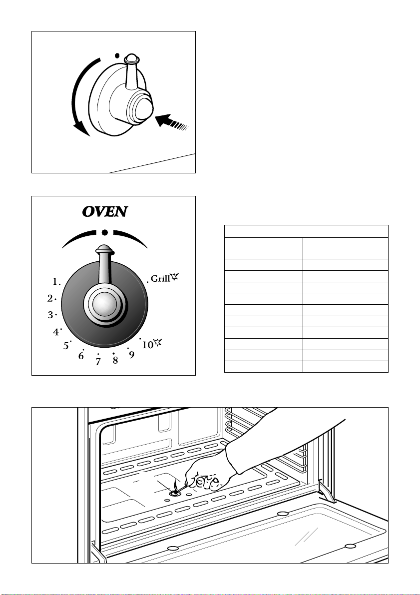
– Turn the oven on to the maximum
temperature (position ) to
eliminate possible traces of grease
from the oven burner. The same
operation should be followed for grill
burner.
IMPORTANT PRECAUTIONS
AND RECOMMENDATIONS
After having unpacked the appliance,
check to ensure that it is not damaged
and that the oven door closes correctly.
In case of doubt, do not use it and
consult your supplier or a professionally
qualified technician.
Packing elements (i.e. plastic bags,
polystyrene foam, nails, packing straps,
etc.) should not be left around within
easy reach of children, as these may
cause serious injuries.
●ATTENTION: please peel plastic
cover of both sides and front
before use.
●Do not attempt to modify the technical
characteristics of the appliance as
this may cause danger to users.
●Do not carry out cleaning or
maintenance operations on the
appliance without having previously
disconnected it from the electric
power supply.
●If you should decide not to use this
appliance any longer (or decide to
substitute another model), before
disposing of it, it is recommended that
it be made inoperative in an
appropriate manner in accordance to
health and environmental protection
regulations, ensuring in particular that
all potentially hazardous parts be
made harmless, especially in relation
to children who could play with
unused appliances.
●After use, ensure that the knobs are
in off position.
●Do not allow children or other
unqualified people to use the
appliance without your supervision.
●During and after use of the cooker,
certain parts will become very hot. Do
not touch hot parts.
●Keep children away from the cooker
when it is in use.
●Some appliances are supplied with a
protective film on steel and aluminium
parts. This film must be removed
before using the appliance.
●Fire risk! Do not store flammable
material in the oven and in the
storage compartment.
●Make sure that electrical cables
connecting other appliances in the
proximity of the cooker cannot come
into contact with the hob or become
entrapped in the oven door.
●Do not line the oven walls with
aluminium foil. Do not place baking
trays or the drip tray on the base of
the oven chamber.
●The manufacturer declines all liability
for injury to persons or damage to
property caused by incorrect or
improper use of the appliance.
●The various components of the
appliance are recyclable. Dispose of
them in accordance with the
regulations in force in your country. If
the appliance is to be scrapped,
remove the power cord.

4
1 - COOKING HOB
Fig. 1.1
23
4
5
6
1
COOKING HOB
1. Double-ring burner (PB) 3,45 kW
2. Semi-rapid burner (SR) 1,90 kW
3. Rapid burner (R2) 2,95 kW
4. Auxiliary burner (A) 1,00 kW
5. Semi-rapid burner (SR) 1,90 kW
6. Auxiliary burner (A) 1,00 kW

5
2 - CONTROL PANEL
Fig. 2.1
12 3456789
CONTROL PANEL - Controls description
1. Gas oven control knob
2. Minute counter
3. Front left burner control knob
4. Rear left burner control knob
5. Front central burner control knob
6. Rear central burner control knob
7. Rear right burner control knob
8. Front right burner control knob
9. Rotisserie/oven light control knob

6
3 - USE OF COOKING HOB
GAS BURNERS
Each burner is controlled by a gas tap
assuring the opening and the closing of
the gas supply.
Make the lever of the knob match with
the indicator on the control panel to
obtain:
– symbol ●: off
– symbol : full on (nominal rate)
– symbol : reduced rate
To reduce the gas flow to minimum,
rotate the knob anti-clockwise to point
the lever towards the small flame
symbol.
Fig. 3.1
Other intermediate operating adjust-
ments can be achieved by positioning
the lever between the maximum and
minimum aperture positions, and never
between the maximum aperture and off
positions.
LIGHTING THE BURNERS
To ensure maximum burner efficiency
when using the hob in conjunction
with the main oven, is preferable to
ignite hob burners only after the oven
has been preheated to the desired
temperature (about 10 minutes).
To ignite the burner, the following
instructions are to be followed:
1) Lightly press and turn the knob anti-
clockwise, and position the knob
indicator to the symbol printed on the
control panel (fig. 3.2).
2) Press the knob to operate the electric
ignition; or, in the case of a mains
failure light the burner with a match or
lighted taper.
3) Adjust the burner according to the
setting required.
Fig. 3.2
The maximum aperture position permits
rapid boiling of liquids, whereas the min-
imum aperture position allows slower
warming of food or maintaining boiling
conditions of liquids (simmering).

Fig. 3.4b
Fig. 3.4a
WRONG
CORRECT
CORRECT USE OF
DOUBLE-RING BURNER
The flat-bottomed pans are to be placed
directly onto the pan-support.
When using a WOK you need to place
the supplied stand in the burner to avoid
any faulty operation of the double-ring
burner (Fig. 3.4).
7
CHOICE OF THE BURNER
On the control panel, near every knob,
there is a diagram that indicates which
burner is controlled by that knob.
The suitable burner must be chosen
according to the diameter and the
capacity used.
As an indication, the burners and the
pots must be used in the following way:
It is important that the diameter of the
pot be suitable to the potentiality of the
burner so as not to compromise the high
output of the burners and therefore
energy waste.
A small pot on a large burner does not
give you a boiling point in a shorter
amount of time since the capacity of
heat absorption of a liquid mass
depends on the volume and the surface
of the pot.
Fig. 3.3
BURNERS POT DIAMETER
Auxiliary 12 - 16 cm
Semi-rapid 16 - 22 cm
Rapid 20 - 24 cm
Double-ring up to 30 cm
do not use pans with concave or convex bases

8
Attention: the oven door becomes
very hot during operation.
Keep children away.
4 - GAS OVEN
GENERAL FEATURES
The oven is supplied completely clean; it
is advisable, however, upon first use, to
turn the oven on to the maximum tem-
perature (position ) to eliminate
possible traces of grease from the oven
burner. The same operation should be
completed for grill burner.
The gas oven is provided with two burn-
ers:
a) Oven burner, mounted on the lower
part of the oven (wattage: 6,20 kW)
b) Grill burner, mounted on the upper
part of the oven (wattage: 4,65 kW).
If hob burners are already in use it is
preferable to await about 10 minutes
before operating the oven.
OVEN BURNER
This carries out normal “oven cooking”.
The gas flow to the burner is regulated
by a thermostat which maintains the
oven temperature constant.
The control of the temperature is
assured by a thermostatic probe posi-
tioned inside the oven.
The probe must be always kept in its
housing, in a clean condition, as an
incorrect position or encrustment may
cause an alteration in the control of the
temperature.
IGNITION OF THE OVEN BURNER
The thermostat allows the automatic
control of the temperature.
The gas delivery to the oven burner is
controlled by a two way thermostatic tap
(oven and grill burners) with flame-fail-
ure device.
To light the oven burner operate as fol-
lows:
1) Open the oven door
2) Lightly press and turn the thermostat
knob anti-clockwise to max position
“”.
3) Press the knob right down to prime
the electric ignition.
WARNING: Risk of explosion! The
oven door must be open during
this operation.
In case of power cut, press the knob
and immediately approach a lighted
match to the opening “A” (fig. 4.3).
Never continue this operation for
more than 15 seconds. If the burn-
er has still not ignited, wait for
about 1 minute prior to repeating
the ignition.
4) Wait about 10/15 seconds after the
burner lighting before releasing the
knob (time of priming of the valve).
5) Close the oven door slowly and adjust
the burner according to the power
required.
If the flame extinguishes for any reason,
the safety valve will automatically shut
off the gas supply to the burner.
To re-light the burner, first turn the oven
control knob to position ●, wait for at
least 1 minute and then repeat the
lighting procedure.

9
Fig. 4.1
Fig. 4.2
Fig. 4.3
A
OVEN THERMOSTAT
The numbers 1 to 10 printed on the con-
trol panel (fig. 4.2) indicate the increas-
ing oven temperature value (see table
below - THERMOSTAT GRADE TABLE).
To regulate the temperature, set the
chosen number onto the knob indicator.
THERMOSTAT GRADE TABLE
Thermostat Oven
indicator temperature
1 150 °C
2 165 °C
3 180 °C
4 195 °C
5 210 °C
6 225 °C
7 240 °C
8 255 °C
9 270 °C
10 285 °C

10
OVEN COOKING
Before introducing the food, preheat the
oven to the desired temperature.
For a correct preheating operation, it is
advisable to remove the tray from the
oven and introduce it together with the
food, when the oven has reached the
desired temperature.
Check the cooking time and turn off the
oven 5 minutes before the theoretical
time to recuperate the stored heat.
COOKING EXAMPLES
Temperatures and times are approxi-
mate as they vary depending on the
quality and amount of food.
The times shown apply to the oven
already heated to the required cooking
temperature.
Remember to use ovenproof dishes and
to adjust the oven temperature during
cooking if necessary.
DISHES TEMPERATURE
Lasagne 190°
Baked pasta 190°
Pizza 220°
Creole rice 190°
Baked onions 190°
Spinach crêpes 185°
Potatoes baked in milk 185°
Stuffed tomatoes 180°
Cheese soufflé 170°
Roast veal 180°
Grilled veal chops 210°
Chicken breasts with tomato 180°
Grilled chicken - roast chicken 190°
Veal loaf 175°
Roast beef 170°
Fillet of sole 175°
Aromatic hake 170°
Beignets 160°
Ring cake 150°
Plum tart 170°
Jam tartlets 160°
Sponge cake 170°
Sweet dough 160°
Sweet puffs 170°
Plain sponge cake 170°

11
IGNITION OF THE GRILL BURNER The grill burner generates the infra-red
rays for grilling.
To light the grill burner operate as follow:
1) Open the oven door.
2)
Lightly press and turn
the thermostat
knob clockwise to the
position (fig. 4.4).
3) Press the knob right down to prime
the electric ignition.
WARNING: Risk of explosion!
The
oven door must be open during this
operation.
In case of power cut, press the knob
and put a lighted match to the right
and left side of the burner (fig. 4.5).
Never continue this operation for
more than 15 seconds. If the burn-
er has still not ignited, wait for
about 1 minute prior to repeating
the ignition.
4) Wait about 10/15 seconds after the
burner lighting before releasing the
knob (time of priming of the valve).
5) Half-close the oven door slowly.
If the flame extinguishes for any reason,
the safety valve will automatically shut
off the gas supply to the burner.
To re-light the burner, first turn the oven
control knob to position ●, wait for at
least 1 minute and then repeat the
lighting procedure.
Do not grill with oven door closed.
Always fit the heat shield supplied
with the cooker under the front
panel before commencing
operations (Fig. 4.6).
WARNING. The heat shield and the
oven door reaches a very high
temperature whilst in use. Keep
children away and allow to cool
before removing.
Fig. 4.4
Fig. 4.5

12
Notes:
– The grill burner has only one setting, that is full-on
– It is important that the heat shield is fitted the correct way up, as shown in the figure 4.6.
Fig. 4.7
OVEN LIGHT
The cooker is equipped with a light that illumi-
nates the oven to enable visually controlling the
food that is cooking.
This light is controlled by a switch knob (fig. 4.7).
Fig. 4.6
IMPORTANT WARNING
For best results when using the grill, place the shelf on the second level and when
using the grill pan handle avoid contact with the heat shield which will be
HOT during use

13
ROTISSERIE
This is used for spit roasting under the
grill and comprises:
– an electric motor fitted to the rear of the
oven
– a stainless steel skewer provided with
slide-out heatless handgrip and two
sets of adjustable forks
– a skewer support to be fitted in the mid-
dle runner.
The rotisserie motor is operated by the
oven switch (Fig. 4.8).
USE OF THE ROTISSERIE
– Insert the tray into the lowest rack holder of the oven and insert the rod support into
the intermediate rack holders.
– Put the meat to be cooked onto the rod, being careful to secure it in the center with the
special forks.
– Insert the rod into the side gear opening “P” (fig. 4.9)
– Remove the grip “H” by turning it to the left.
– Insert completely the rotisserie support; the shaft “S” must be inserted in the spit motor
collar “G”.
The rotation direction of the rotisserie can be either clokwise or counter-clockwise.
Fig. 4.8
Fig. 4.9
G
S
H
P

14
5 - MINUTE COUNTER
Fig. 5.1
MINUTE MINDER (Fig. 5.1)
The minute counter is a timed acoustic
warning device which can be set for a
maximum of 60 minutes.
The knob (Fig. 5.1) must be rotated
clockwise as far as the 60 minute posi-
tion and then set to the required time by
rotating it anticlockwise.

15
6 - CLEANING AND MAINTENANCE
IMPORTANT NOTES
Installation, and any demonstration, information or adjustments are not included in
the warranty.
The cooker must be installed by a qualified person in accordance with the Gas
Safety (Installation and Use) (Amendment) Regulations 1990 and the relevant
building/l.E.E Regulations.
Failure to install the appliance correctly could invalidate any manufacturers warranty
and lead to prosecution under the above quoted regulation.
In the UK C.O.R.G.I registered installers are authorised to undertake the installation
and service work in compliance with the above regulations. All Curry’s authorised
installers are C.O.R.G.I. registered.
Attention
The appliance gets very hot, mainly around the cooking areas. It is very
important that children are not left alone in the kitchen when you are cooking.
Do not use a steam cleaner because the moisture can get into the appliance
thus making it unsafe.

16
S
D
B
C
Fig. 6.1
ASSEMBLING THE BACKGUARD
1. Insert the side supports S and D into the backguard B (see fig. 6.1)
2. Insert the backguard group into the support guides in the cooker
3. The backguard can be removed for cleaning or fixed with a screw through the hole
C.
CLEANING
All the enamelled parts must be cleaned
with a sponge and soapy water or other
non-abrasive products.
Dry preferably with a soft cloth.
Acidic substances like lemon juice,
tomato sauce, vinegar etc. can damage
the enamel if left too long.
STAINLESS STEEL SURFACES
The stainless steel front panels on this
cooker (facia, oven door, drawer or
storage compartment) are protected by
a finger-print proof lacquer.
To avoid damaging this lacquer, do not
clean the stainless steel with abrasive
cleaners or abrasive cloths or scouring
pads.
ONLY SOAP/WARM WATER MUST
BE USED TO CLEAN THE STAINLESS
STEEL SURFACES.

17
Fig. 6.2
REPLACING THE OVEN LIGHT BULB
Switch the oven off at the mains.
When the oven is cool unscrew and
replace the bulb with another one
resistant to high temperatures (300°C),
voltage 230 V (50 Hz), 15 W, E14.
Note: Oven bulb replacement is not
covered by your guarantee.
INSIDE OF OVEN
This must be cleaned after every use.
Remove and refit the side runner frames
as described on the next chapter.
With the oven warm, wipe the inside
walls with a cloth soaked in very hot
soapy water or another suitable product.
The bottom of the oven, side runner
frames, tray and rack can be removed
and washed.
BURNERS
They can be removed and washed only
with soapy water.
Detergents can be used but must not be
abrasive or corrosive.
Do not use abrasive sponges or pads.
Do not put in dishwasher.
After cleaning or washing, check that
burner-caps and burner-heads are dry
before placing them in the respective
housings.
Special attention has to be paid in
order not to exchange the housing of
the small burners shown in fig. 6.2.
It is absolutely necessary to check the
perfect housing of the burner-ring as an
incorrect housing may cause serious
problems.
Check also that the electrodes for
ignition are always clean in order to
ensure a regular spark.
N.B. To avoid damage to the electric
ignition, do not use it when the burners
are not in place.
Burner-cap ring
partially drilled Burner-cap rings
fully drilled
FLEXIBLE TUBE
From time to time, check the flexible
tube connecting the gas supply to the
cooker.
It must be always in perfect condition;
in case of damage arrange for it to be
replaced by a C.O.R.G.I. registered
installer.

18
STORAGE COMPARTMENT
The storage compartment is accessible
through the pivoting panel (fig. 6.4).
Fig. 6.4
Fig. 6.3
OVEN DOOR
The internal glass panel can be easily
removed for cleaning by unscrewing the
4 retaining screws (Fig. 6.3)
Do not store flammable material in
the oven or in the storage
compartment.

19
ASSEMBLY AND DISMANTLING OF
THE SIDE RUNNER FRAMES
– Fit the side runner frames into the
holes on the side walls inside the
oven (Fig. 6.5).
– Slide the tray and rack into the run-
ners (Fig. 6.6).
– To dismantle, operate in reverse
order.
Fig. 6.5
Fig. 6.7
L
F
Fig. 6.6
OVEN FLOOR
The oven floor “F” (fig. 6.7) can be easily
removed to facilitate cleaning.
Remember to replace the floor correctly
afterwards.
Be careful not to confuse the tray “L”
with the oven floor “F”.

20
The oven door can easily be removed as
follows:
– Open the door to the full extent (fig.
6.8A).
– Attach the retaining rings to the hooks
on the left and right hinges (fig. 6.8B).
– Hold the door as shown in fig. 6.8.
– Gently close the door and withdraw the
lower hinge pins from their location
(fig. 6.8C).
– Withdraw the upper hinge pins from
their location (fig. 6.8D).
– Rest the door on a soft surface.
– To replace the door, repeat the above
steps in reverse order.
Fig. 6.8D
Fig. 6.8C
Fig. 6.8B
Fig. 6.8A
REMOVING THE OVEN DOOR
Fig. 6.8
Table of contents
Other Elba Kitchen Appliance manuals

Elba
Elba EIC-1600P User manual

Elba
Elba EJE-J7580(SS) User manual

Elba
Elba ETP-F3218 User manual

Elba
Elba N96 EX 939 S Technical manual

Elba
Elba EJE-9811A User manual

Elba
Elba EJE-A2050 User manual

Elba
Elba EHP-G1583G(RD) User manual

Elba
Elba ESM-2085 User manual

Elba
Elba EEC 563 series User manual

Elba
Elba ETP-G5083(CG) User manual

Elba
Elba EJE-9811A User manual

Elba
Elba CX 906 DF Technical manual

Elba
Elba E K55..220 series Installation and operating instructions

Elba
Elba TP-3511DGT User manual

Elba
Elba EMC-N5017 User manual

Elba
Elba EJE-1302 User manual

Elba
Elba EMC-N9015 User manual

Elba
Elba EMC-F4316 User manual

Elba
Elba EC 967F SS User manual

Elba
Elba EMC-K5015PK User manual