manuals.online logo
Brands
  1. Home
  2. •
  3. Brands
  4. •
  5. SEIAOTEK
  6. •
  7. Switch
  8. •
  9. SEIAOTEK ST-M2404PX User manual

SEIAOTEK ST-M2404PX User manual

User Manual
Packing List
PoE+ Switch
User Manual
Power Cable
Bracket kits
Product description
Device Installation
Installation Precautions
Note
A tamper-evident seal is sealed on a mounting screw of the switch chassis. When the
agent maintains the switch, the maintenance switch is required The seal remains intact.
If the user needs to open the switch case, please obtain the permission of the local agent.
Otherwise, due to all consequences caused by opening the cabinet will be borne by the
user himself.
Prepare the installation tools
1. Static bracelet
2. Screw driver
3. Optional: flat-blade screw driver, needle-nose pliers, diagonal pliers
Install the switch into a 19-inch standard cabinet
Step 2: Use the screws to fix the two L-shaped brackets on both sides of the switch.
Step 1: Check the grounding and stability of the rack-mountable.
To avoid damage to the switch or personal injury caused by improper use, please follow up
the below precautions:
1. During the installation procedure, wear an anti-static wristband, keep the switch powered off.
Ensure that the input voltage under the input voltage range.
2. Ensure that the heat dissipation holes of the switch are well ventilated.
3. Do not disassemble the switch.
4. Do not supply power to the switch before cleaning it. Do not use any liquid to scrub the switch.
5. Keep the switch far away from power lines, lights, and power grids.
Step 3: Place the switch in a proper position in the rack, and fix the L-shaped brackets on the
guide grooves at both ends of the rack with screws (if users required) to ensure that the
switch is installed on the rack smoothly
Install the switch to the desktop
After sticking the foot pads on the four corners of the bottom surface of the switch, please place
and keep the switch face up on the stable desktop.
PoE ports
SFP Slots
Console
Default
Ground terminal
Power connector
Interface/button Description
1-24: 10/100/1000M PoE+ ports, Support Auto-MDI/MDIX function.
1X-4X: 10G SFP+ Slots.
Console port: Connect the Serial Cable to the Serial port of the computer
to manage and configure the switch.
Restart or reset buttons: Press and hold this button around 10 seconds,
the switch will recovery to factory settings.
Connect the power cable with the switch.
Connect the protective ground wire to prevent lightning strikes.
Hardware connection
Connect SFP+ Slots
Step 1: Grab the handle end of the optic fiber module, confirm that the handle of the optic fiber module
facing upwards, and then insert the optical module into the 1X~4X SFP+ Slots of the switch.
Step 2: After confirming the Rx and Tx ports on the optic fiber module, insert the two fiber connectors at
one end of the fiber into the Rx and Tx ports of the optical module respectively, and then plug the
two fiber connectors at the other end of the fiber into the opposite device. Tx and Rx ports.
R
PWR
Link/Act
Indicator light
ON
OFF
ON
Flashing
OFF
Switch power supply is normal
The switch is not powered on or the power supply is abnormal
Port is connected
Port is transmitting data
The port is not connected, or the connection is abnormal
Status Description
24-Port Gigabit Managed Layer 3
PoE+ Switch with 10G SFP+ slots
ST-M2404PX
Power Switch Switch on/off.
PWR
Foot pad
Foot pad
Link/Act 1~24 10/100/1000M PoE+ Ports
1X~4X: 10G SFP+ Slots
Default
Console
Ground terminal
Power connector
Power switch
Warranty Card
Note: Please refer to the User Manual for Detail Warranty policy
Model NO.
Serial NO.
Purchase Date
RMA Number
Return Reason
Customer Name
Customer Address
Customer Email
Interface
PoE Ports 1~24: 10/100/1000M PoE+ Ports
SFP Slots 1X~4X: 10G SFP+ Slots
Name
Model
24-Port Gigabit Managed Layer 3 PoE+ Switch with 10G SFP+ Slots
ST-M2404PX
Connect Rj45 port
Connect one end of the network cable to the Rj45 port of the switch, and the other end to the
RJ45 Ethernet port of the opposite network device.
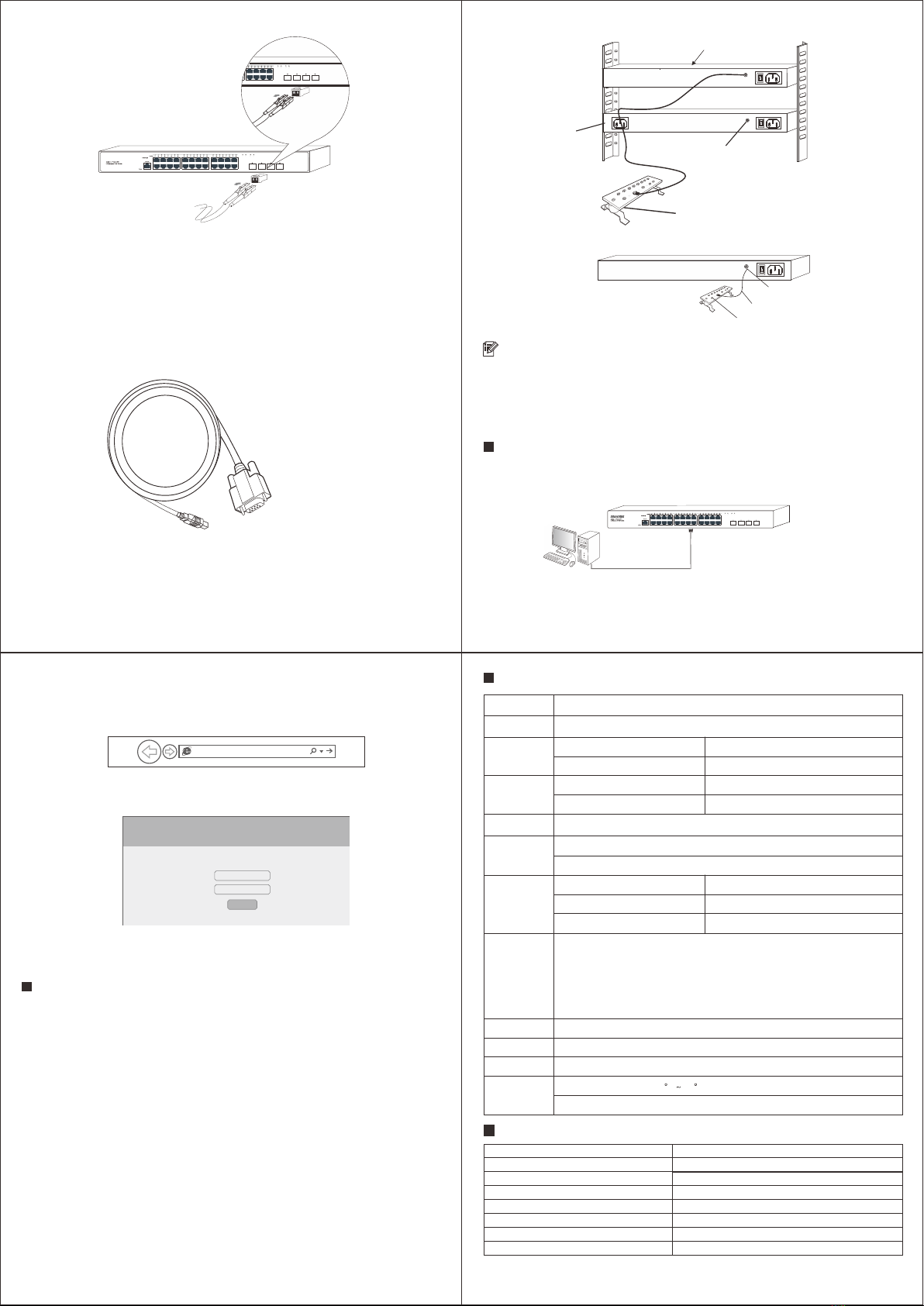
Connect to the console port
Connect the RS232 DB9 male end of the serial cable to the computer, and connect the Rj45end
to the Conport port of the switch.
Connect the ground wire
Step 1: Connect one end of the ground wire to the ground terminal of the switch.
Step 2: Connect the other end of the ground wire to other equipment that has been grounded,
or directly connect it to the ground bar of the equipment room engineering terminal.
Note

Log in to the WEB Management Page
1. Connect the computer to the switch through a network cable.
2. Set the computer's local IP address to 192.168.1.X (X is 2~254, and is not occupied by other
devices), and the subnet mask is 255.255.255.0.
The ground wire of the switch should be connected to the engineering ground of the equipment
room. The grounding fire water pipe and the lightning rod of building are not properly grounded.
3. Open the computer's local browser (take IE as an example), enter http://192.168.1.1 into
the address, and press Enter to log in Switch Web Management page.
http://192.168.1.1
4. Enter the user name and password (the default is admin), and then click the login button.
Username:
Password:
Login
5. Log in to the switch web management page and start to configure the switch.

Specifications

Common Tips
What should I do if I can’t log in to the switch's web management page?
Please try the following solutions:
Confirm that the switch is powered on.
1. Confirm that the computer and the switch network cable are connected properly.
2. Confirm that the computer's Ethernet (or local connection) IP address has been set to
192.168.1.X (X is 2~254, and it is not occupied by other devices).
3. Clear the cache of the browser, or change the browser, and confirm that the connection
method of the browser is never dial connection.
4. Turn off the computer's firewall or replace a computer.
5. Confirmed that there is no other devices whose IP address is also 192.168.1.1.
6. If you still cannot log in after the above operations, please restore the factory settings.
The specific operations as follows:
7. When the Power indicator is on, press and hold the Default button on the front
panel of the switch around 10 seconds.
8. Release when all the indicators are on. When the Power indicator keeps on or the
SYS indicator flashing again, the factory settings recovery successfully.
LED
PWR , Link / Act
Store-and-forward
Half-duplex back pressure and IEEE802.3x full-duplex flow control
Bandwidth 128Gbps
Packet Forwarding Rate 95.23Mpps
MAC Address 32K
Network
Standards
IEEE802.3i 10BASE-T, IEEE802.3u 100BASE-TX, IEEE802.3ab 1000BASE-T,
IEEE802.3z 1000BASE-LX, IEEE802.3x 10G BASE-R,
IEEE802.3x Flow Control, IEEE802.3az EEE,
IEEE802.1p, IEEE802.1x, IEEE802.1d, IEEE802.1s,
IEEE802.3af Power over Ethernet,
IEEE802.3at Power over Ethernet
Processing
Types
Performance
Specification
Power lnput AC 100~240V 50~60Hz
Dimension 440mm (L) x 285mm (W) x 44mm (H)
Cables UTP Cat 5 or above
Environment
Specification
Working Temperature: 0 C 45 C, Humidity: 10% ~ 90% RH non-condensing
Storage Temperature: 20°C ~ 70°C, Humidity: 5% ~ 95% RH non-condensing
PoE Power Max PoE Output (Channel)
PoE Power Budget
30W
450W

Rs232 DB9 male end
Rj45 end
This switch
Other devices
Or
Ground terminal
Ground wire
Ground bar
Ground terminal
Ground wire
Ground bar
Switch
PC Cable

Other SEIAOTEK Switch manuals

SEIAOTEK ST-G16T User manual

SEIAOTEK

SEIAOTEK ST-G16T User manual

SEIAOTEK ST-IND0402TS User manual

SEIAOTEK

SEIAOTEK ST-IND0402TS User manual

SEIAOTEK ST-F0802PE User manual

SEIAOTEK

SEIAOTEK ST-F0802PE User manual

SEIAOTEK ST-M4804TS User manual

SEIAOTEK

SEIAOTEK ST-M4804TS User manual

SEIAOTEK ST-IND0402MPS User manual

SEIAOTEK

SEIAOTEK ST-IND0402MPS User manual

SEIAOTEK ST-M1602PS User manual

SEIAOTEK

SEIAOTEK ST-M1602PS User manual

SEIAOTEK ST-G08T User manual

SEIAOTEK

SEIAOTEK ST-G08T User manual

SEIAOTEK ST-M4804TX User manual

SEIAOTEK

SEIAOTEK ST-M4804TX User manual

SEIAOTEK ST-M2404PS User manual

SEIAOTEK

SEIAOTEK ST-M2404PS User manual

SEIAOTEK ST-IND0802PS User manual

SEIAOTEK

SEIAOTEK ST-IND0802PS User manual

SEIAOTEK ST-IND0806MPS User manual

SEIAOTEK

SEIAOTEK ST-IND0806MPS User manual

SEIAOTEK ST-M2402TS User manual

SEIAOTEK

SEIAOTEK ST-M2402TS User manual

Popular Switch manuals by other brands

Avaya ERS 3500 Series manual

Avaya

Avaya ERS 3500 Series manual

ZyXEL Communications GS2200 Series manual

ZyXEL Communications

ZyXEL Communications GS2200 Series manual

LEGRAND Pro 21 7756 31 manual

LEGRAND

LEGRAND Pro 21 7756 31 manual

Siemens SIRIUS S0 Original operating instructions

Siemens

Siemens SIRIUS S0 Original operating instructions

D-Link DES-7200 Hardware installation guide

D-Link

D-Link DES-7200 Hardware installation guide

Phoenix Contact PSR-CT Series operating instructions

Phoenix Contact

Phoenix Contact PSR-CT Series operating instructions

Assa Abloy Securitron WSS Wave Sense installation instructions

Assa Abloy

Assa Abloy Securitron WSS Wave Sense installation instructions

THOMSON GRASS VALLEY TRITON TTN-BTS-3232/140 installation manual

THOMSON

THOMSON GRASS VALLEY TRITON TTN-BTS-3232/140 installation manual

Orei UHD-401MV user manual

Orei

Orei UHD-401MV user manual

3Com Security Switch 6200 Hardware and Software Users Guide

3Com

3Com Security Switch 6200 Hardware and Software Users Guide

TC Communications TC3720 user manual

TC Communications

TC Communications TC3720 user manual

Microsens MS650850M Application

Microsens

Microsens MS650850M Application

StarTech.com 5G4AINDNP-USB-A-HUB quick start guide

StarTech.com

StarTech.com 5G4AINDNP-USB-A-HUB quick start guide

GESTRA NRS 1-51 installation instructions

GESTRA

GESTRA NRS 1-51 installation instructions

H3C S5120-HI Series quick start

H3C

H3C S5120-HI Series quick start

MHZ PowerView instruction manual

MHZ

MHZ PowerView instruction manual

SMC Networks TigerSwitch SMC6948L2 Specifications

SMC Networks

SMC Networks TigerSwitch SMC6948L2 Specifications

LEGRAND HA7110 installation instructions

LEGRAND

LEGRAND HA7110 installation instructions

manuals.online logo
manuals.online logoBrands
  • About & Mission
  • Contact us
  • Privacy Policy
  • Terms and Conditions

Copyright 2025 Manuals.Online. All Rights Reserved.