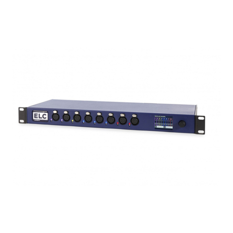
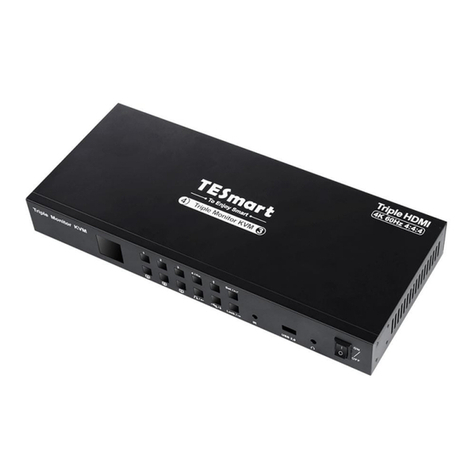
ELC dmXLAN switch8GB User manual

Users manual for
dmXLAN switch8GB

dmXLAN switch8GB
Gigabit Ethernet switch with fast redundancy loop, easy vlan support and dmx-ethernet filtering
options.
The switch as an easy to use graphical user interface with an encoder with push function.
Connections
8x Cat5e 1000/100/10 ruggedized XLR style RJ46 connections.
2x SFP Cages for fiber optic modules.
AC power supplied via a fixed mains load (100-240Vac)
Function of an Ethernet switch
A Ethernet switch is used to connect multiple Ethernet devices. An Ethernet connection cannot be
passively daisy changed or y-split. It needs an active unit to split the signal, either a hub or a switch.
Hubs have a lot of disadvantages like changes of collisions, unable to mix network speeds and no
intelligence. A Ethernet switch can be linked multiple in a row. All connections are full-duplex and there
are no collisions. The dmXLAN switch8GB also integrates a processor to add functionality like: an
easy graphical user interface, fast redundancy loops and dmx-ethernet filtering options. All functions
and ports settings can be programmed on the unit or via the free dmXLAN software.
Explanations on vlan’s
In a “normal”network situation, all devices share 1 network and are possible to communicate. In
some situations this is not a desirable situation and a separation of networks is needed. One option is
to physically create 2 networks, running twice the cabling. A other option is the use of vlan’s or virtual
lan. A vlan is created by creating trunk-lines between switches and labeling the device connections on
the switch. The device connections (port on the switch that connects to a device) are labels with a v-
lan number. There are more then 4000 possible v-lan’s, but only a few are normally used. The trunk-
line between the switches will carry all the network data of all v-lan’s but the packets are labeled so a
receiving switch can determine what signal goes to what device connection.
Example use below is mixing a audio network with a lighting control network.

Fast Redundancy loops
In a show situation, a network failure will bring down the show. As all communication from front of
house to the stage runs thru a single network, this becomes a single point of failure. If this link goes
wrong all communication to the stage is gone and there is no show. To solve this a backup loop can
be easily created. In a network situation connecting switches in a loop is “dangerous” to the network,
as packets with go round and round in this loop and there by filling up the complete network bandwidth
with useless data.
The switches need to be setup for this loop to work. A loop programmed on a switch always has 2
ports, the port and a partner. Multiple loops can be created on a switch that work independently. This
loop functions needs to be setup in each switch in the loop. The switches then workout the rest. One
network link will automatically be assigned as a backup and the loops integrity is continually checked.
If a link failure occurs, the backup network link is enabled and a message will be send to the dmXLAN
control software. When the failed network link is back, the backup link is automatically disabled again.
The activation time is 100 milliseconds, compared to office time backup systems like RSTP (rapid
spanning tree protocol) that have a recovery time of almost a minute.
Fiber Optic links
Cat5e cables can be used for Ethernet with 1 Gigabit with no problems, but only up to 100 meters. To
go longer length, fiber optic cables are needed. To connect fiber optic links to the switch8GB, SFP
modules are needed to be plugged into the back of the unit in the Option slots for ports 7 and 8.
Looking from the back the most left slot is for port 7 and the right option slot (next to port 8) is used for
port 8.
The SFP fiber optic modules need to match the fiber cable
used. These modules can be sources from multiple vendors.
The type that can be supplied by ELC lighting is the
TP-SM311LM:
- 1.25Gbs
- Max 550 meter
- 50/125um or 62.5/125um Multi-Mode
- LC connector

Operation
The dmXLAN switch8GB can be operated in 2 ways. Either thru the front panel user interface or via
the free dmXLAN software. The software can be downloaded from www.elclighting.com
Control via the User interface
Main display
The main display has multiple information pages. The page can be selected with the rotary encoder.
The lower row indicates the status of each port. If a port is setup to be a loop and the loop is faulty, the
indicator will blink.
Page 1 name of the switch and link indications
Page 2 vlan / Trunk / Loop settings of each port
The lower row of the ports indicate the vlan id / trunk mode / or loop partner. If empty, the port is
operating in a special mode.
Page 3 switch ID number that can be used by the dmXLAN software
Page 4 IP address of the unit
Page 5 Firmware version of the unit
To go into the setup menu, press the encoder button
Setup Menu
The setup menu as a number of options:
- Exit: return to the main screen and save all settings
- Create loop: easy way to quickly setup a loop, automatically setup the ports used
- Port 1 – 8: changes settings of the network ports. The line also indicates the current setting
- Set ID: change the dmXLAN id
- Rename Config: change the name of the switch (and its configuration) as seen on the main
display and in the dmXLAN software.
- Network settings: set the ip address and v-lan settings of the unit.
- Backlight: change the display backlight timing
- Factory Defaults: change all the settings back
Use the encoder to select an item and press enter to select. In the sub menus, select a setting to
change and press the encoder. The line will then show a box around the selected item and turn the
encoder to change the value. When done press the encoder again to go back to the selection mode.

Create Loop
This menu will make the correct settings for the 2 ports used in the loop.
First select the first port and then the partner (second) port of the loop.
Next select “Set Loop Now” to make the adjustment, or select cancel if you don’t want to make the
change.
Change port settings for port 1 – 8
The port mode can be
- Disabled: port function is disabled
- Normal: the port acts as a normal device port with a vlan id. The default vlan id is 1.
- Trunk/Loop: in this mode, the port is used as a connection between 2 switches. The port on
both sides of the connection needs to be set in this mode ( trunk/loop ). This connection will
carry all the data from all vlans, but with the vlan label added.
- Artnet Filter: special feature to limit the dmx-ethernet output of the port. This can help when
devices are connected that cannot handle a lot of dmx-ethernet traffic. You can setup what
dmx-ethernet universes are able to go to the device. Changing the filter setup requires the
dmXLAN software. The filter always is working on the “Control VLan”. The control vlan is
described in the section “Network Settings”.
The type of the connection is by default set to auto, but can be limited to 10 or 100mbit if needed.
Fiber optic Modules
On ports 7 and 8 it is also possible to set the type to Fiber. This will enable the SFP fiber optic module
in the corresponding option slot. Please Note: after making this change, you’ll first need to exit the
setup menu so that the changes are saved and the do a power cycles (power off and back on the
unit). The modules need to be inserted before power on. Of the modules cannot be found or there is a
problem during power on, the switch will use the cat5 option of that port.
If the Mode is set to Trunk/Loop, a loop partner can be given to create a loop. If no loop partner is set,
the port will act as a trunk with no backup mode.
Then select Save and Exit to confirm, or Cancel and Exit to discard the changes.
Set ID
In this menu it is possible to change the ID of the unit. The ID is used by the dmXLAN software to
match predefined devices in the software to detected devices on the network, instead of using ip-
addresses.
Turn the encoder to change the digits and press the encoder to select the next one. After the third
digit, the menu exits.
Rename Configuration
Change the name of the configuration. Turn the encoder to change the character, and press to select
the next one. After the last character the menu exits.

Network Settings
Change the ip address settings in this menu. The ip address settings can be set to dynamic (if used on
a network with a DHCP server), or with a static ip address and netmask. The ip[ address settings are
only needed for use with the dmXLAN software. When a dmXLAN system is used with the art-net
protocol, most of the time it will be working in the 2.x.x.x ip address range. The switch then needs an
ip address of 2.x.x.x (where the value of x can be between 1 and 254, but no 2 devices should have
the same address). The netmask needs to be set to 255.0.0.0.
Explanation on IP-address and Netmask
In order for 2 devices on a ip network to be able to communicate, then ip-address range needs to
match. Network address ranges are matched using the netmask. The numbers when the netmask has
255 need to be the same, where the netmask is 0 the numbers are not compared.
A device with settings 192.168.1.3/255.255.255.0 cannot communicate with a device that has
192.168.2.5/255.255.255.0 as the third number (1 and 2) are not the same.
Control VLan ID setting
The switch is used on a vlan based network. In order for a computer running the dmXLAN software,
both the computer and the cpu of the switch need to be on the same vlan. The vlan would normaly be
the vlan used for the dmx-ethernet lighting protocols. As the CPU is “connected” to this vlan, dmXLAN
software can communicate with the switch and also the dmx-ethernet filter functions will work.
Backlight
Here it is possible to change the displays backlight behavior.
Factory Default
Recall the factory settings
General Information
CE – Product
The dmXLAN switch8gb permits to the CE requirements set up by the European Community. This can
be recognized by this label on the outside of the product.
Technical Specifications switch8GB:
Power: 100-240 VAC 47-440 Hz 10VA max
Dimensions 483 x 44 x 150 mm (19"1HE)
Table of contents
Other ELC Switch manuals
Popular Switch manuals by other brands

VONROC
VONROC GP804AA Original instructions
Moxa Technologies
Moxa Technologies EtherDevice EDS-P510 Series Hardware installation guide
Cisco
Cisco Catalyst Series Switch 2940 datasheet

LEGRAND
LEGRAND 7 521 90 quick start guide
TRENDnet
TRENDnet TL2-E284 Quick installation guide

Phonocar
Phonocar 5-981 Mounting instructions
