Elcometer 4340 User manual

English
Elcometer 4340
Motorised Film Applicator
Operating Instructions
4340_TMA_0319_00_06.fm Page -1 Thursday, January 21, 2010 10:15 AM

R
English
This product meets the Electromagnetic Directive, Low Voltage
Directive and the Machinery Directive.
The product is Class A, Group 1 ISM equipment according to CISPR 11
Group 1 ISM product: A product in which there is intentionally generated and/
or used conductively coupled radio-frequency energy which is necessary for
the internal functioning of the equipment itself.
Class A product are suitable for use in all establishments other than domestic
and those directly connected to a low voltage power supply network which
supplies buildings used for domestic purposes.
is a registered trademark of Elcometer Limited.
All other trademarks acknowledged.
© Copyright Elcometer Limited. 2010.
All rights reserved. No part of this Document may be reproduced, transmitted,
transcribed, stored (in a retrieval system or otherwise) or translated into any
language, in any form or by any means (electronic, mechanical, magnetic,
optical, manual or otherwise) without the prior written permission of
Elcometer Limited.
A copy of this Instruction Manual is available for download on our Website via
www.elcometer.com.
Doc.No. TMA-0319 Issue 06
Text with Cover No: 19335
R
4340_TMA_0319_00_06.fm Page 0 Thursday, January 21, 2010 10:15 AM

1
R
CONTENTS
Section Page
1 About your applicator . . . . . . . . . . . . . . . . . . . . . . . . . . . . . . . . . . . . . . 2
2 Getting started . . . . . . . . . . . . . . . . . . . . . . . . . . . . . . . . . . . . . . . . . . . . 4
2.1 The parts of your applicator . . . . . . . . . . . . . . . . . . . . . . . . . . . . . . . . . . . 4
2.2 Power input . . . . . . . . . . . . . . . . . . . . . . . . . . . . . . . . . . . . . . . . . . . . . . . 4
2.3 The control panel . . . . . . . . . . . . . . . . . . . . . . . . . . . . . . . . . . . . . . . . . . . 5
2.4 Product overflow tray . . . . . . . . . . . . . . . . . . . . . . . . . . . . . . . . . . . . . . . . 7
2.5 Caution. . . . . . . . . . . . . . . . . . . . . . . . . . . . . . . . . . . . . . . . . . . . . . . . . . . 7
2.6 Setting the carriage start and stop positions . . . . . . . . . . . . . . . . . . . . . . 8
2.7 Fitting attachments to the carriage. . . . . . . . . . . . . . . . . . . . . . . . . . . . . . 9
3 Mounting the substrate . . . . . . . . . . . . . . . . . . . . . . . . . . . . . . . . . . . . 10
3.1 Mounting using the spring clamp . . . . . . . . . . . . . . . . . . . . . . . . . . . . . . 10
3.2 Mounting using vacuum. . . . . . . . . . . . . . . . . . . . . . . . . . . . . . . . . . . . . 10
4 Using film applicators . . . . . . . . . . . . . . . . . . . . . . . . . . . . . . . . . . . . . 12
5 Using spiral bar coaters . . . . . . . . . . . . . . . . . . . . . . . . . . . . . . . . . . . 14
6 Producing a specimen. . . . . . . . . . . . . . . . . . . . . . . . . . . . . . . . . . . . . 15
6.1 Before you start . . . . . . . . . . . . . . . . . . . . . . . . . . . . . . . . . . . . . . . . . . . 15
6.2 Procedure . . . . . . . . . . . . . . . . . . . . . . . . . . . . . . . . . . . . . . . . . . . . . . . 15
6.3 After application . . . . . . . . . . . . . . . . . . . . . . . . . . . . . . . . . . . . . . . . . . . 16
7 Heated tables . . . . . . . . . . . . . . . . . . . . . . . . . . . . . . . . . . . . . . . . . . . . 17
7.1 Water heated table. . . . . . . . . . . . . . . . . . . . . . . . . . . . . . . . . . . . . . . . . 17
7.2 Electrically heated table. . . . . . . . . . . . . . . . . . . . . . . . . . . . . . . . . . . . . 18
8 Maintenance . . . . . . . . . . . . . . . . . . . . . . . . . . . . . . . . . . . . . . . . . . . . . 19
9 Technical specification . . . . . . . . . . . . . . . . . . . . . . . . . . . . . . . . . . . . 19
10 Accessories . . . . . . . . . . . . . . . . . . . . . . . . . . . . . . . . . . . . . . . . . . . . . 20
11 Related equipment. . . . . . . . . . . . . . . . . . . . . . . . . . . . . . . . . . . . . . . . 21
4340_TMA_0319_00_06.fm Page 1 Thursday, January 21, 2010 10:15 AM

2
R
hank you for purchasing this Elcometer Motorised Film Applicator.
Welcome to Elcometer.
Elcometer are world leaders in the design, manufacture and supply of
inspection equipment for coatings and concrete.Our products cover all aspects
of coating inspection, from development through application to post application
inspection.
The Elcometer Motorised Film Applicator, is a world beating product. With the
purchase of this product you now have access to the worldwide service and
support network of Elcometer. For more information visit our website at
www.elcometer.com
1 ABOUT YOUR APPLICATOR
The Elcometer Motorised Film Applicator is a robust, reliable and extremely
flexible machine. The machine is used to prepare a wide variety of product
samples including paint, varnish, cosmetics, glue, etc., on various substrates
such as contrast charts, sheet steel, plastic foils and glass.
The Motorised Film Applicator is designed for use with spiral bar coaters and
film applicators (depending upon attachments specified at time of ordering).
The substrate is held securely in place on the table of the machine by clamp or
vacuumaand the machine spreads the product in a consistent and reproducible
film across the surface.
1.1 These instructions
These instructions describe the operation of the following Elcometer Motorised
Film Applicators:
Model No. Vacuum table type Table heating
Elcometer 4340/10- non-vacuum none
Elcometer 4340/11- non-vacuum external water bathb
Elcometer 4340/12- non-vacuum internal electric element
Elcometer 4340/100 perforated none
Elcometer 4340/101 single channel none
Elcometer 4340/102 double channel none
Elcometer 4340/110 perforated external water bathb
a. Substrate securing method depends upon model.
b. Supplied ready to be fitted with a temperature bath. Temperature bath not included.
T
4340_TMA_0319_00_06.fm Page 2 Thursday, January 21, 2010 10:15 AM

3
R
Elcometer 4340/111 single channel external water bathb
Elcometer 4340/112 double channel external water bathb
Elcometer 4340/120 perforated internal electric element
Elcometer 4340/121 single channel internal electric element
Elcometer 4340/122 double channel internal electric element
1.2 Standards
The Elcometer Motorised Film Applicator can be used in accordance with the
following standard, ASTM D 823-C.
1.3 What the box contains
• Elcometer Motorised Film Applicator
• Substrate securing clip on table
• Bubble spirit level
• Operating instructions
Your Motorised Film Applicator may be supplied with additional attachments,
depending upon which options were specified at the time of ordering:
• Film applicator attachment (with weight and hexagonal wrench)
• Spiral bar coater attachment (with weight x 2, hexagonal wrench, rubber
mat x 2, and zero bar)
• Film applicator and spiral bar coater attachment (with weight x 3, hexagonal
wrench, rubber mat x 2 and zero bar)
The Elcometer Motorised Film Applicator is packed in a cardboard and foam
package. Please ensure that this packaging is disposed of in an
environmentally sensitive manner. Consult your local Environmental Authority
for further guidance.
To maximise the benefits of your new Elcometer Motorised Film
Applicator please take some time to read these Operating Instructions. Do
not hesitate to contact Elcometer or your Elcometer supplier if you have
any questions.
4340_TMA_0319_00_06.fm Page 3 Thursday, January 21, 2010 10:15 AM

4
R
2 GETTING STARTED
This section of the instructions is intended for first-time users of the Motorised
Film Applicator. It contains information on the parts and controls of your
Applicator and advice on safe use of the equipment. When you have finished
reading this section you will be ready to start using the Applicator.
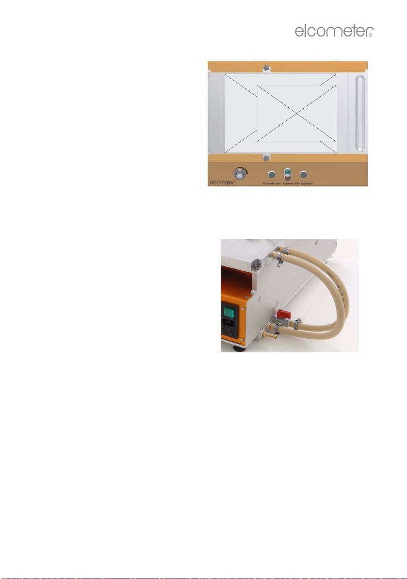
2.1 The parts of your applicator
Figure 1. Parts of the Applicator
(this model fitted with spiral bar coater attachment)
2.2 Power input
The power input socket at the rear of the Applicator (Figure 2) is protected by
two fuses - see “Technical specification” on page 19 for fuse rating.
Figure 2. Power input socket, main on/off switch and fuse holder
Table
Controls
Carriage Substrate
4340_TMA_0319_00_06.fm Page 4 Thursday, January 21, 2010 10:15 AM
5
R
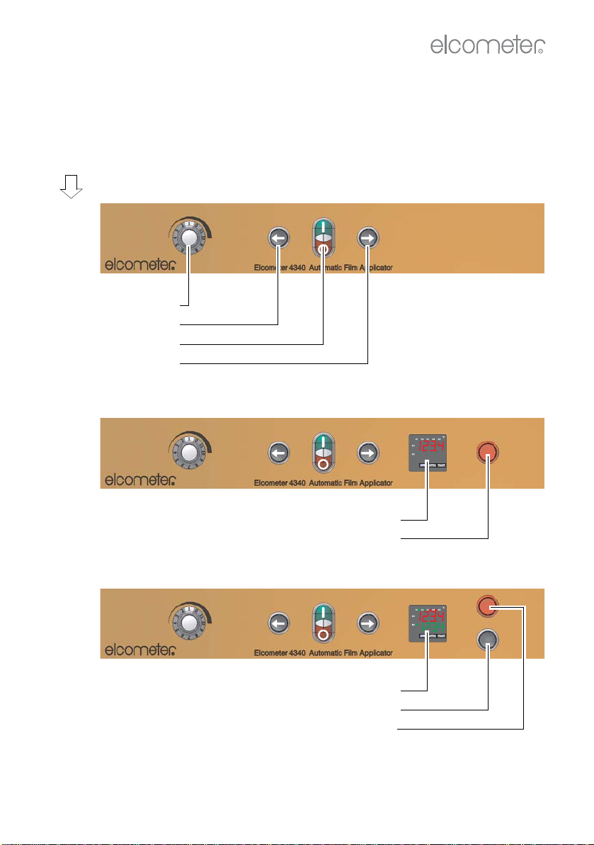
2.3 The control panel
The Applicator is operated using the controls mounted on the front panel of the
machine. The controls fitted to your Applicator depend upon model number:
Figure 3. Control panels - all models
10-
100
101
102
Carriage speed
Carriage return
Power on/off
Carriage start
Model
Number
11-
110
111
112
Temperature display
Hot surface warning lamp
12-
120
121
122
Temperature control/display
Electrically heated table on/off
Hot surface warning lamp
4340_TMA_0319_00_06.fm Page 5 Thursday, January 21, 2010 10:15 AM

6
R
2.3.1 Power on/off
To switch on the Applicator, ensure the main power on/off switch at the rear of
the Applicator is in the ‘on’ position and then press the green button on the
control panel. The indicator light in the centre of the button will illuminate.
To switch the Applicator off, press the red button on the control panel.
2.3.2 Carriage start and return
To start the carriage, press carriage start . The carriage will stop when it
reaches the stop position.
To return the carriage to the start, press carriage return . The carriage will
stop when it reaches the start position.
To stop the carriage movement at any time, press the red button on the control
panel.
The start and stoppositions can be adjusted-see“Settingthecarriagestart and
stop positions” on page 8.
2.3.3 Setting the carriage speed
Carriage speed is adjustable; there are 11 preset speeds which are selected by
rotating the carriage speed selector knob.
Note: Do not adjust the carriage speed while the carriage is moving.
Carriage speed
selector position Carriage speed
(mm per second)
15
210
320
430
540
650
760
870
980
10 90
11 100
4340_TMA_0319_00_06.fm Page 6 Thursday, January 21, 2010 10:15 AM
7
R
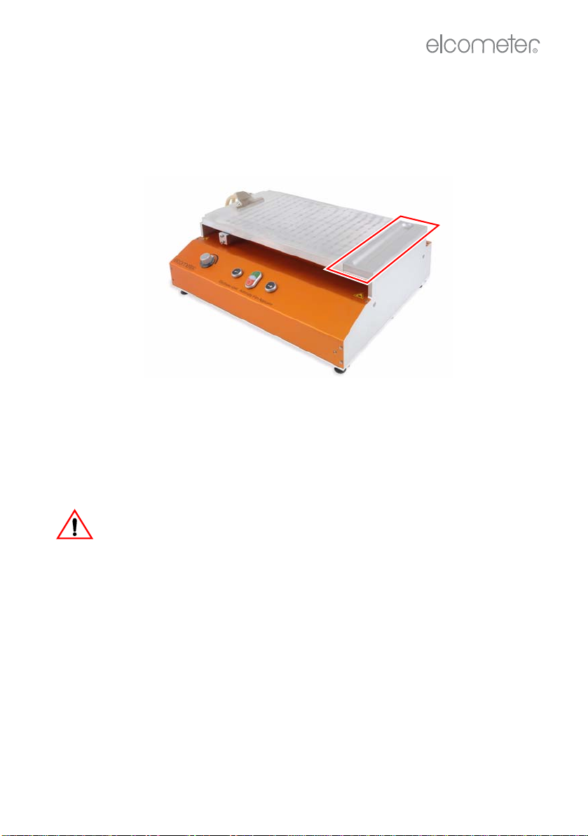
2.4 Product overflow tray
(These instructions apply only to models fitted with a vacuum table)
The product overflow tray acts as a small reservoir to catch waste product which
is pushed off the end of the table by the applicator. The tray can be removed to
allow waste product to be cleaned off.
Figure 4. Product overflow tray
2.5 Caution
The Elcometer Motorised Film Applicator has been manufactured with your
safety in mind. However, improper use can result in damage to the Applicator.
Please observe the precautions discussed in these operating instructions.
To reduce the risk of electric shock do not open the housing of the
Applicator. There are no user-serviceable parts inside.
To reduce the risk of fire or electric shock, do not expose the Applicator to rain
or excess moisture.
The mains plug on your Applicator may be fitted with a fuse. When replacing
this fuse, ensure a fuse of the correct rating is used.
4340_TMA_0319_00_06.fm Page 7 Thursday, January 21, 2010 10:15 AM
8
R
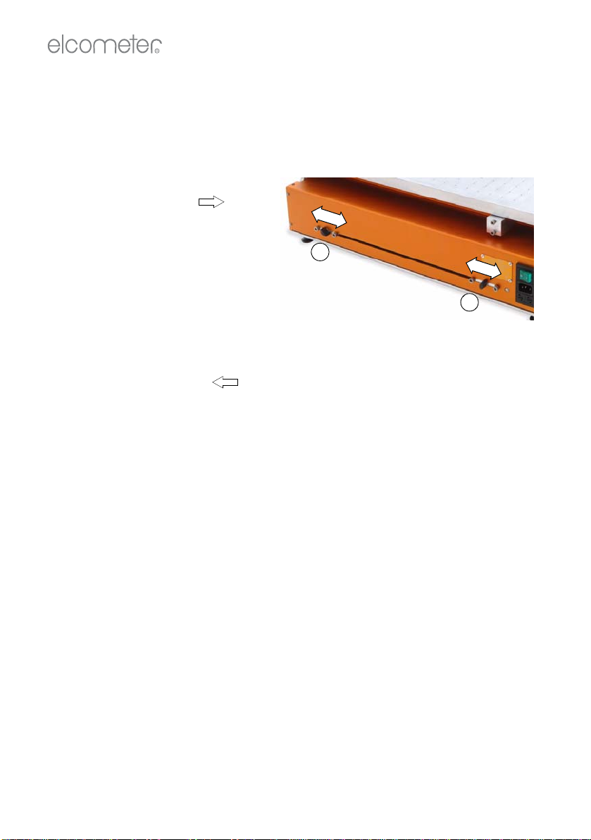
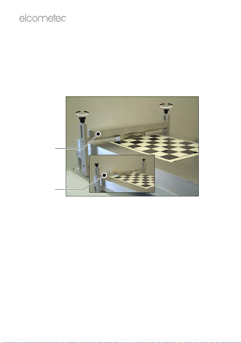
2.6 Setting the carriage start and stop positions
Set the start and stop positions of the carriage to adjust the distance the
carriage travels during operation.
To adjust start position
1. Switch machine on.
2. Press carriage start . The
carriage will stop automatically
when it reaches the stop
position.
3. Unscrew knob (2), (Figure 5).
4. Slide knurled knob to new
position and tighten.
To adjust stop position
1. Switch machine on.
2. Press carriage return . The carriage will stop automatically when it
reaches the start position.
3. Unscrew knob (1), (Figure 5).
4. Slide knurled knob to new position and tighten.
Figure 5. Rear of machine showing
carriage start and stop adjustments
1
2
4340_TMA_0319_00_06.fm Page 8 Thursday, January 21, 2010 10:15 AM

9
R
2.7 Fitting attachments to the carriage
Any additional attachments which may have been ordered with your Motorised
Film Applicator are supplied loose and must be fittedto the carriage before use.
Three attachments are available: Film Applicator, Spiral Bar Coater and
Combined Film Applicator/Spiral Bar Coater - See “Accessories” on page 20.
All the attachments are fitted to
the carriage in an identical
manner using the four screws
shown (A).
To fit an attachment:
• Using the hexagonal wrench
supplied with the attachment,
loosen and remove the four
screws.
• Place the attachment onto the
carriage, align the mounting
holes, refit the four screws and
then tighten.
The illustration shows the Spiral
Bar Coater attachment fitted to the
carriage and secured by the
screws (A). The Film Applicator is
fitted to the carriage using the
same procedure.
Note: The table fitted to your Motorised Film Applicator may be different to the
table shown in the images above, but the attachments are fitted to the carriage
in the same way.
A
A
A
4340_TMA_0319_00_06.fm Page 9 Thursday, January 21, 2010 10:15 AM
10
R
3 MOUNTING THE SUBSTRATE
To ensure an even application of the product film, the substrate must be
mounted carefully on the table.
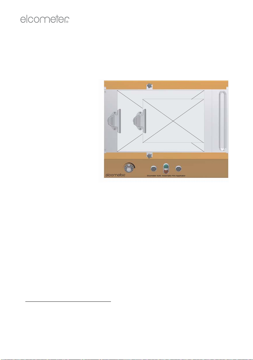
3.1 Mounting using the spring clamp
1. There are two
mounting positions for
the clamp. Screw the
clamp onto the table in
the position which suits
the dimensions of the
substrate (Figure 6).
2. Clean the surface of
the table and the
underside of the
substratec.
3. Position the substrate
on the table and clamp
in place; A3 size
substrate occupies
virtually all of the table,
A4 size substrate
should be positioned
on the right side of the
table as shown (Figure 6).
3.2 Mounting using vacuum
These instructions apply to models fitted with a perforated vacuum table. A
channelled vacuum table only works with A3-size substrates.
1. Clean the surface of the table and the underside of the substrate.
c. When using a spiral bar coater to apply the product film, place the soft rubber mat supplied
with your applicator between the table and the substrate. Use of the rubber mat raises the
substrate sufficiently to ensure it comes into contact with the spiral bar coater. Ensure both
sides of the rubber mat are clean before use.
A3
A4
Figure 6. Clamp and substrate positioning
4340_TMA_0319_00_06.fm Page 10 Thursday, January 21, 2010 10:15 AM
11
R
2. Position the substrate on the
table; A3 size substrate
occupies virtually all of the
table, A4 size substrate should
be positioned on the right side
of the table as shown (Figure
7).
3. Attach the vacuum pump (see
“Accessories” on page 20)
using the hose to the
connection on the left hand
side of the machine (Figure 8).
4. If the specimen size is A3, turn
the vacuum control marked ‘A3
ON/OFF’ to the ‘on’ position
(in-line with the hose), as
shown in Figure 8.
If the specimen size is A4, turn
the vacuum control marked ‘A3
ON/OFF’ to the ‘off’ position (at
right angles to the hose).
5. Switch on the vacuum pump.
The substrate will then be drawn onto the table and held firmly.
6. Mask off areas of the table not covered by the specimen. Use ‘Scotch Tape’
or a similar removable thin tape. This prevents product getting into the
vacuum table or into the gap between the end of the table and the product
overflow tray.
Note: The single channel and double channel vacuum tables are used for thin
substrate materials such as paper (single channel) and foils (double channel)
A3
A4
Figure 7. Substrate positioning on
vacuum table
Figure 8. Vacuum pump connection
and control valve
4340_TMA_0319_00_06.fm Page 11 Thursday, January 21, 2010 10:15 AM
12
R
4 USING FILM APPLICATORS
4.1 Film applicators with a film applicator carriage
1. Mount substrate on table (see “Mounting the substrate” on page 10).
2. Place film applicator on substrate until it is touching the pushing bar.
3. Check to ensure the top surface of the pushing bar is below the top of the
film applicator tool. If adjustment of the height of the pushing bar is
required, rotate the knobs (Figure 9) an equal amount.
Figure 9. Standard carriage
Rotate knobs to adjust height of pushing bar
4. When using a light applicator such as the Baker, place the weight onto the
two locating pegs. The weight rests on top of the film applicator and holds it
firmly in contact with the substrate.
The film applicator is now mounted correctly and is ready for application of the
product film.
Pushing bar
Weight
4340_TMA_0319_00_06.fm Page 12 Thursday, January 21, 2010 10:15 AM

13
R
4.2 Film applicators with a spiral bar coater carriage
1. Rotate carriage to raised position.
2. Fit applicator pushing bar into position
and tighten knurled screws (Figure
10).
3. Mount substrate on table (see
“Mounting the substrate” on page 10).
4. Place applicator onto substrate in front
of pushing bar (Figure 11).
5. Check that the top surface of the
pushing bar is below the top surface of
the applicator. Adjust the height of the
pushing bar if necessary.
6. When using a light applicator such as
the Baker, place the weight onto the
two locating pegs. The weight rests on
top of the film applicator and holds it
firmly in contact with the substrate
(Figure 12).
Your film applicator is now mounted
correctly and is ready for application of the
product film.
Figure 10. Applicator
pushing bar
Figure 11. Applicator in
position on substrate
Figure 12. Weight pressing
down on applicator
4340_TMA_0319_00_06.fm Page 13 Thursday, January 21, 2010 10:15 AM

14
R
5 USING SPIRAL BAR COATERS
Spiral bar coaters can only be used on Motorised Film Applicators fitted with a
bar coater carriage. The rubber mat must be placed on the table when using a
spiral bar coater.
1. Rotate carriage to raised position.
2. Remove weights.
3. Open clamps.
4. Fit spiral bar coater.
5. Close clamps.
6. Refit weights.
7. Clean the surface of the table and the rubber mat.
8. Position the rubber mat on the table and secure using the clamp.
Note: The rubber mat must be positioned accurately along the centre line of the
table. Ensure that the carriage does not touch the rubber mat during its travel.
9. Rotate carriage to lower position.
Check to ensure the spiral bar coater
is touching the surface of the rubber
mat. To adjust the height of the spiral
bar coater, rotate the two screws (1) at
the rear of the carriage (Figure 13).
10.Clean the underside of the substrate,
position the substrate on the rubber
mat and secure using the clamp.
Note: Never start the carriage without a
substrate in place on the rubber mat.
Friction between the rubber and the bar/
spiral bar coater will cause the carriage to
become jammed.
1
Figure 13. Bar height
adjustment screw
Figure 14. Bar coater carriage
with spiral bar coater
4340_TMA_0319_00_06.fm Page 14 Thursday, January 21, 2010 10:15 AM

15
R
6 PRODUCING A SPECIMEN
6.1 Before you start
•Ensure the Applicator table is level.
Place the supplied bubble level on the table and adjust the feet of the
Applicator until the table is level.
•Select carriage speed.
See “Setting the carriage speed” on page 6.
•Set carriage travel distance.
See “Setting the carriage start and stop positions” on page 8.
•Mount the substrate.
See “Mounting using vacuum” on page 10.
•Mount the applicator tool.
See “Using film applicators” on page 12 and “Using spiral bar coaters” on
page 14.
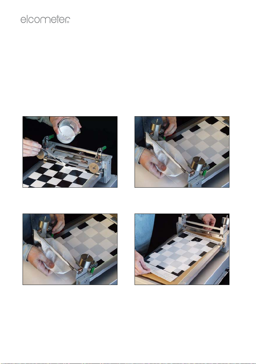
6.2 Procedure
See Figure 15.
1. Apply the product
Pour the product onto the substrate in front of the applicator tool. Use a
brush or similar tool to spread out the product across the width of the
substrate.
2. Start the carriage
Press the green button to switch on the Applicator. Press carriage start
. The carriage will travel across the substrate and will stop
automatically when it reaches the stop position.
3. Clean the applicator tool
If using a spiral bar coater, rotate the carriage to its raised position and
immediately wipe away any excess product to prevent product dripping on
the substrate.
If using a film applicator, lift the film applicator from the substrate and wipe
away any excess product to prevent product dripping on the substrate.
4. Return carriage
Press carriage return . The carriage will return to the start position.
Press the red button to switch off the Applicator.
4340_TMA_0319_00_06.fm Page 15 Thursday, January 21, 2010 10:15 AM
16
R
5. Remove substrate
Switch off the vacuum pump (vacuum table models only) and remove the
substrate from the table.
6.3 After application
1. If your Applicator is fitted with a product overflow tray, lift the tray off the
machine, remove all product residue and refit.
2. Clean all splashes of product off the machine.
3. Clean your applicator tool very thoroughly.
Figure 15. Film application procedure (using spiral bar coater)
Apply the product Start the carriage
Clean the applicator tool Remove the substrate
4340_TMA_0319_00_06.fm Page 16 Thursday, January 21, 2010 10:15 AM

17
R
7 HEATED TABLES
Some Elcometer Motorised Film Applicator models are fitted with vacuum and
non-vacuum heated tables. Heating is either by an external water bath or
internal electrical elements.
Take care when using a heated table. The temperature of the table can
reach 200°C and can cause serious burns.
The outlet pipe of the vacuum pump must be located in a safe place to
avoid burns caused by the waste hot air.
The vacuum pump must be compatible with operation at temperatures
up to 100°C or 200°C (depending upon model). It is advisable to switch
the pump on when the equipment is ready for applying the coating on the
substrate and to switch the pump off immediately after the coating
application. Extended use of the pump at high temperature can cause
grease in bearings to dissolve and pipes to soften.
When using a rubber mat with a heated table, do not allow the
temperature of the table to exceed +50°C. Temperatures in excess of
+50°C can cause the rubber to degrade.
Always bear in mind that the low thermal conductivity of the rubber material will
tend to insulate the substrate from the heat of the table. A temperature probe
placed on the top surface of the rubber mat will provide a more accurate
measure of temperature than the temperature display on the front panel of the
instrument (contact Elcometer or your Elcometer supplier for details of our wide
range of digital thermometers).
7.1 Water heated table
Elcometer models 4340/11-, 110, 111 & 112 include a table designed to be
heated by water (maximum temperature 100°C).
These models have a temperature display mounted on the front panel. This
display does not control the temperature of the table, it only displays the
temperature. The buttons and controls on the temperature display have no
function.
A red indicator will illuminate (when the Applicator is switched on) when
the table is above 50°C.
Do not touch the table when the red indicator is illuminated.
Control of the temperature of the hot water must be provided by an external
water heating system (not supplied with the instrument).
4340_TMA_0319_00_06.fm Page 17 Thursday, January 21, 2010 10:15 AM

18
R
7.2 Electrically heated table
Elcometer models 4340/12-, 120, 121 & 122 include a table
heated by electricity (maximum temperature 100°C or
200°C).
This model has a temperature display/controller mounted on
the front panel.
A red indicator will illuminate (when the Applicator is
switched on) when the table is above 50°C.
Do not touch the table when the red indicator is illuminated.
Operation
1. To switch on the Applicator, press the green start button and the heat switch
located below the hot surface temperature indicator.
2. The temperature display will show the current temperature of the table (PV).
3. To adjust the temperature of the table:
• Use the (increase) and (decrease) buttons to adjust the set-
point temperature (SV).
• When the desired set-point temperature is displayed press . The
temperature PV will increase up to SV.
4. Place the substrate on the table and leave the Applicator and the substrate
to reach the set temperature:
At 50°C: allow 20 minutes
At 100°C: allow 60 minutes
At 200°C: allow 90 minutes
The film applicator must also be heated to the correct temperature. This
can be done in an oven or by placing the applicator on the table and leaving
it long enough to heat through completely.
Note: The temperature of the table will always be slightly lower than the set
point shown on the temperature controller. This is due to heat loss from the
surface of the table. For accurate temperature measurement it is advisable to
use a digital thermometer with a probe to measure the temperature of the
surface directly.
Note: Take care and observe the following limitations when using a rubber mat
on a heated table; the rubber has a maximum working temperature of 50°C and
it will provide an effective layer of insulation between the specimen and the
heated table.
4340_TMA_0319_00_06.fm Page 18 Thursday, January 21, 2010 10:15 AM
Other manuals for 4340
1
Table of contents
Other Elcometer Industrial Equipment manuals


