ELDAN MPR200T User manual

ELDAN MULTI PURPOSE RASPER
MPR200T
Serial number: 34222
Delivery date:
Customer:

Manual for
ELDAN MULTI PURPOSE RASPER
MPR200T
1.1

ELDAN Recycling A/S Page 1
TABLE OF CONTENTS Page
1. INTRODUCTION...........................................................................3
2. SAFETY INSTRUCTIONS .............................................................4
3. MACHINE INFORMATION ............................................................7
3.0 Equipment description of MPR200T..............................................................8
3.1 Input definition:..............................................................................................8
3.2 Technical Specifications for MPR200T..........................................................9
4. SAFETY EQUIPMENT.................................................................11
4.0 Introduction .................................................................................................12
4.1 Main switch .................................................................................................12
4.2 Emergency stops.........................................................................................12
4.3 Safety switch ...............................................................................................12
4.4 Service switch .............................................................................................13
4.5 Fire equipment for MPR200T ......................................................................14
4.6 Fire Hazard. ................................................................................................15
5. INSTALLATION..........................................................................16
5.0 Introduction .................................................................................................17
5.1 Lifting points ................................................................................................17
5.2 Gravity and weight statement......................................................................18
5.3 Recommended floor fixing methods ............................................................18
5.4 Dimensions of clearance needed for service and maintenance ..................19
5.5 Power and service details and requirements...............................................19
5.6 Test before starting .....................................................................................19
5.7 Foundations ................................................................................................19
6. SETTING THE MPR200T............................................................20
6.0 Introduction .................................................................................................21
6.1 Safety information .......................................................................................21
6.2 Opening the upper part with hopper ............................................................23
6.3 Cleaning the Rasper and surrounding areas...............................................24
6.4 Information regarding adjustment/exchange of knives ................................25
6.5 Exchange of the static knives......................................................................27
6.6 Exchange of the flying knives......................................................................30
6.7 Adjustment of the distance between static and flying knives.......................33
6.8 Dismounting and mounting of knife holders for 25mm flying knives............34
6.9 Checking .....................................................................................................36
6.10 Closing the upper part with hopper..............................................................36
6.11 Removing the discharge hopper and the screen.........................................37
6.12 Mounting of the screen and discharge hopper ............................................40

ELDAN Recycling A/S Page 2
6.13 Torque.........................................................................................................42
6.14 Motor ...........................................................................................................43
7. OPERATION ...............................................................................44
7.0 Introduction .................................................................................................45
7.1 Safety statements........................................................................................45
7.2 Operational procedure.................................................................................48
7.3 Useful information regarding the process....................................................49
7.4 Steel and dust outlet....................................................................................51
7.5 Safety statement regarding emergency stops .............................................52
8. MAINTENANCE..........................................................................53
8.0 Introduction .................................................................................................54
8.1 Maintenance directions ...............................................................................56
8.2 Lubrication scheme summary .....................................................................58
8.3 Adjustment of clutch....................................................................................60
8.4 Adjustment of belt drive...............................................................................62
8.5 Grinding of knives........................................................................................63
9. SPARE PARTS............................................................................66
9.0 Introduction .................................................................................................67
9.1 Spare parts philosophy................................................................................67
9.2 Spare parts stock level recommendations...................................................67
10. DISPOSAL OF THE MPR200T ....................................................69

1. INTRODUCTION
1.1 Congratulations on your purchase of an ELDAN machine. Like many cus-
tomers who have gone before you, you hav e just entered into what we hope
will be a long and beneficial partnership with us.
1.2 To ensure that you get the very best from your machine, we give you this
manual, which forms an indispensable part of your operation.
Please read it carefully as you will find it contains the necessary information to in-
stall, set, operate and maintain the machine in a safe and efficient manner.
1.3 You will notice that we suggest safe operation before efficient operation, not
because we don't think the machine is effi cient but because we feel it is im-
portant for everybody that the machine is operated safely.
To reinforce this you will see in the text the symbol The section on
safety explains what this means, but for the purpose of this introduction,
wherever you see as part of an instruction, it is essential that you
carry out the instruction exactly as s pecified and that you do not attempt to
overlook the safety element in any way.
1.4 Should you require clar ification regarding any of the information or should
you wish to purchase further copies of this manual, please contact your
ELDAN agent or contact us direct.
ELDAN RECYCLING A/S
Vaerkmestervej 4
DK-5600, Faaborg,
Denmark
Tel: +45 63 61 25 45
Fax: +45 63 61 25 40
E-mail: [email protected]
Homepage: www.eldan-recycling.com
ELDAN Recycling A/S Page 3

2. SAFETY INSTRUCTIONS
It is a condition that the person, who is going to operate the machine, has
been educated or is familiar with machines of the same type.
Ordinary safety rules :The ordinary safety rules of the country in
question must always be obeyed.
Before starting, check that:
All protection devices are placed correctly.
Check conveyors for left tools, screws, bolts, etc.
The operator must be absolutely certain that no service, repair or any
other kind of work on the machine is being undertaken before start-
ing the machine.
The machine is to be adjusted according to the directions in the
manual.
Check the starting procedure in the manual.
During operation:
Do not feed objects into the machine, which may cause damage to
the machine.
Safety during operation:
Never try to remove jammed material or foreign bodies in the rotor
house, etc. until it has been checked that the machine is fully iso-
lated electrically. This means turn off and lock all main switches be-
fore working on the machine.
ELDAN Recycling A/S Page 4

When the machine is not delivered with special silencing equipment,
operators must carry earplugs or hearing protectors.
Before the operator begins greasing/maintenance work on the
machine the following precautions should be followed:
In case of stops for maintenance, damage etc. turn off and lock all
main switches before working on the machine. Repair and mainte-
nance work must not be carried out before the machine has been
brought to a complete stop.
After the machine has been stopped there is a caster time of approx.
1 minute. Do not touch rotor and other rotating parts before the ma-
chine has been brought to a complete stop.
Working on the machine, opening of inspection doors or removing
protection screens and safety devices while the machine is operat-
ing, is absolutely prohibited and highly dangerous.
When opening or closing the machine nobody but the operator must
be on or near the machine.
Personal security when carrying out service:
Electrical installations and repairs must only be carried out by
authorised personnel.
The processing area must be satisfactory illuminated so that there are
no dark corners. Illumination must however not be dazzling. The sup-
ply must not be taken from the machine as this must be disconnected
during service work.
It is dangerous to climb the machine. Always use a platform or a step-
ladder where service from the ground is not possible.
ELDAN Recycling A/S Page 5
Dust masks are necessary when cleaning the machine.

Use gloves for hand protection by maintenance work etc. The ma-
chine can be very hot after continuous operation.
When replacing the knives the use of safety glasses is necessary be-
cause of the danger of splinters when the knives are exposed to
strokes and bumps.
Oil leaks from hydraulic tubes or pipes may come with such force
that the oil may penetrate the skin. In such cases a doctor's help
should be sought immediately in order to prevent severe infections.
ELDAN Recycling A/S Page 6

ELDAN Recycling A/S Page 7
3. MACHINE INFORMATION
3.0 Equipment description of MPR200T..............................................................8
3.1 Input definition:..............................................................................................8
3.2 Technical Specifications for MPR200T..........................................................9

ELDAN Recycling A/S Page 8
3.0 Equipment description of MPR200T
This machine is a heavy duty Rasper ideally suited to the harsh environ-
ment of tyre shredding.
To ensure its durability t he main housing is fitted with replaceable wear
plates and the rotor is manufactur ed from wear resistant and hardened
steel.
Other features include a quick-change kn ife system and a rotor, which is
easily removed.
To enable the screen to be easily cleaned or changed, the screen fits into
a hydraulically operated swinging cradle t hat allows it to be lowered from
the cutting chamber in a matter of seconds.
The transmission system is a combination of 2 motors placed on each side
of the machine, and a belt drive bet ween the motors and the rotor shaft.
The number of belts in each side is 10 pieces.
Mechanical overload protection is provided by friction clutches.
The main housing is construct ed with double skinned walls. The wear
plates are mounted on the inside of the inner skin and the main bearings
are mounted on the outside of the outer skin.
In the case that material such as dust, rubber granulates etc. does get
forced between the wear plates, the ma terial falls into the void between
the skins rather than into the rotor bearings. For further protection of the
bearings a wiper has been mounted between the skins.
Should the rotor and flywheel be stalled by extreme overload, a differential
speed detector protects the transmission.
The Rasper is equipped with a Serv ice Platform to enable service and
maintenance work to be carried out with ease.
3.1 Input definition:
The MPR200T has been designed to process whole steel radial car tyres
up to a size of max tyre height of 250 and max. tyre diameter of 800 mm
or pre-shredded car, light truck and truck tyres with a max. chunk size of
300 mm.
Should other kinds of input materi al than the above mentioned be used as
input material this will be at the customer's own risk.

ELDAN Recycling A/S Page 9
3.2 Technical Specifications for MPR200
Rotor length:- 2000 mm
Rotor diameter:- 400 mm
Cutting diameter:- 506 mm
R.P.M. of rotor:- 144
Cutting speed:- 3,82 m/sec
Knives:- 25 flying
26static
Motor:- 2x110 kW 734 rpm, 50 Hz.
Belt drive:- 2x10 pcs SPC, length 5600 mm
Total weight:- Approx. 24.000 kg
Machine weight:- 11500 kg
Weight of inlet hopper:- 2300 kg
Weight of flywheel cover:- 500 kg/each
Motor for hopper lift:- P = 0,75 kW
Total width:- 3850 mm
Total height:- 4600 mm
Total length:- 3000 mm
Inlet height:- 4300 mm

Figure 1
ELDAN Recycling A/S Page 10

ELDAN Recycling A/S Page 11
4. SAFETY EQUIPMENT
4.0 Introduction .................................................................................................12
4.1 Main switch .................................................................................................12
4.2 Emergency stops.........................................................................................12
4.3 Safety switch ...............................................................................................12
4.4 Service switch .............................................................................................13
4.5 Fire equipment for MPR200T ......................................................................14
4.6 Fire Hazard. ................................................................................................15

ELDAN Recycling A/S Page 12
4.0 Introduction
In this section the safety equipment for the MPR200T will be described.
It is important that the instructions ar e followed very carefully to avoid dam-
age to the operator and the machine.
4.1 Main switch
The machine is equipped with a main swit ch, which can be locked. The main
switch disconnects all voltage to the machine and it is placed on the electrical
cabinet.
4.2 Emergency stops
The machine is equipped with two emer gency stops. One is placed on the
machine and one is placed on the electrical cabinet.
The function of the emergency stops is as follows:
1) When activated all volt age to the machine as well as inlet and outlet con-
veyors is disconnected immediately.
2) An emergency stop can only be reset deliberately. This does not mean
that the machine starts automatically, but only that it is possible to start the
machine again.
4.3 Safety switch
The MPR200T is equipped with a safety system, which protects the operator
from the rotating parts of the machine during maintenance work.
The greatest advantage of the system is that it also protects the operator
from the caster, which appears after the machine has been shut down elec-
trically.
The machine is equipped with a number of switches, which should be liber-
ated before hoppers, upper part etc. can be opened, see Figure 2.
The safety switch can be liberated, when the machine has been brought to a
complete stop and the service key on the electrical cabinet is in zero-position.
Note: After stop a certain period of time must pass, before the switches can
be liberated.

Figure 2
4.4 Service switch
When operating the machine, the switch should be in Position "1".
By repair, maintenance and cleaning the se rvice switch should be set to Po-
sition "0" and removed.
The hydraulic pumping unit for opening of upper part with hopper as well as
screen can only be operated with the service switch in zero-position. Once
the upper part with hopper or screen is opened the hydraulic pump must be
switched off. At the same time the main switch must be disconnected and
locked.
Note: After the machine has been stopped a fixed period of time will have to
pass, before the switches can be released.
ELDAN Recycling A/S Page 13

4.5 Fire equipment for MPR200T
The water spraying system
The Rasper is equipped with a water sp raying system with the purpose of re-
ducing the fire risk, but also with the purpose of lubricating/cooling in the rotor
housing.
When processing tyre material in t he MPR200T quite an amount of rubber
and textile dust is liberated and this is quite inflammable.
During operation sparks are produced in the rotor housing. Therefore a water
spraying system is required to moisten t he dusty air in the rotor housing thus
reducing the risk of the sparks from setting fire to the dust.
Water nozzles have been placed in the inlet hopper of the Rasper and be-
tween the sidewalls of the Rasper. The water spraying system operates un-
der normal water pressure and the c onnection is placed on the side of the
Rasper. The water pressure is adjusted by means of a handle, which is also
placed on the side of the Rasper.
The water supply is controlled electrically by means of a magnet valve placed
on the water supply of the machine. This means that the water supply is acti-
vated/stopped when the machine is either started up/shut down.
When processing tyres the water spraying system must always be con-
nected!
The pressure is adjusted in such a way that there is always a fine mist of wa-
ter steam in the rotor housing and between the sidewalls.
It is recommended to clean the water nozzles for dirt once a week.
ELDAN Recycling A/S Page 14

4.6 Fire Hazard.
Please observe the risk of fire, which is always present when processing in-
flammable scrap. Please make the necessa ry precautions to prevent a situa-
tion to occur which may cause a fire i.e. secure following:
that your scrap does not contain explosives or flammable liquids.
that your equipment is always in an optimal condition.
that you operate your equi pment according to the written or verbal in-
structions.
that you use skilled an experienced labour.
that your facilities are clean and tidy.
that you have taken all possible measures of fire-extinguishing.
that you have involved the advisor y support of the Fire-department in
this process.
Eldan Recycling A/S rejects any responsib ility for fires, which occur in con-
nection with the process.
ELDAN Recycling A/S Page 15

ELDAN Recycling A/S Page 16
5. INSTALLATION
5.0 Introduction .................................................................................................17
5.1 Lifting points ................................................................................................17
5.2 Gravity and weight statement......................................................................18
5.3 Recommended floor fixing methods ............................................................18
5.4 Dimensions of clearance needed for service and maintenance ..................19
5.5 Power and service details and requirements...............................................19
5.6 Test before starting .....................................................................................19
5.7 Foundations ................................................................................................19

5.0 Introduction
Within this section we have set out the necessary information to ensure
the safe and correct method of installi ng the machine. Set out below is the
instructions and guide lines to de scribe how the operation should be un-
dertaken.
5.1 Lifting points
The machine shall be lifted/transported by means of a crane. On the main
machine there are mounted lifting hoo ks for this purpose. Lifting
hooks/places are shown on the following drawing, Figure 3 - Pos. 1.
Figure 3
Other machine parts are lifted by forkli ft/strap. The strap is placed suitable
regarding the centre of gravity.
If you are in any doubt regarding safe li fting, seek advice from a specialist
lifting company.
ELDAN Recycling A/S Page 17
5.2 Gravity and weight statement
The gravity point of this machine is approx. 2,3 meters from the ground
and it weighs approx. 22000 kg in tota l / inlet hopper approx. 2000 kg/ fly-
wheel cover approx. 500 kg and the flywheel approx. 2000 kg.
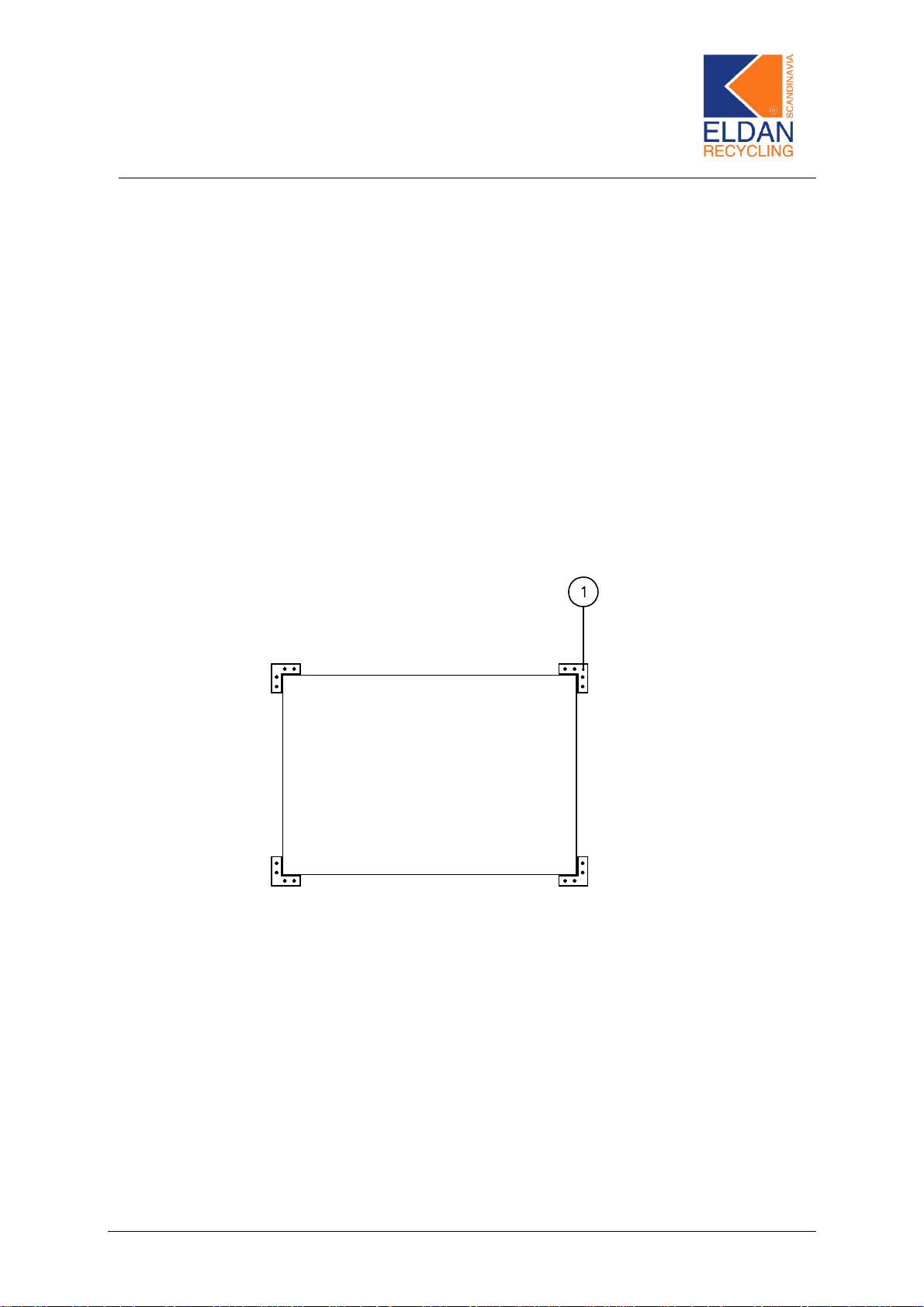
5.3 Recommended floor fixing methods
When fixing the machine it is essential t hat the base is flat and level. If this
is not possible it will be necessary to level the floor.
When final placing of the machine is known the machine is fastened to the
floor by means of the enclo sed clamps and expansion bolts, Figure 4 -
Pos. 1.
Figure 4
ELDAN Recycling A/S Page 18
Table of contents


