eldoLED POWERdrive 561/S Quick start guide
© 2015 eldoLED. All rights reserved. v1.3
More documentation and eldoLED’s terms and conditions are available at www.eldoled.com.
Pay attention when connecting the LED groups:
polarity reversal results in no light output and often damages the LEDs
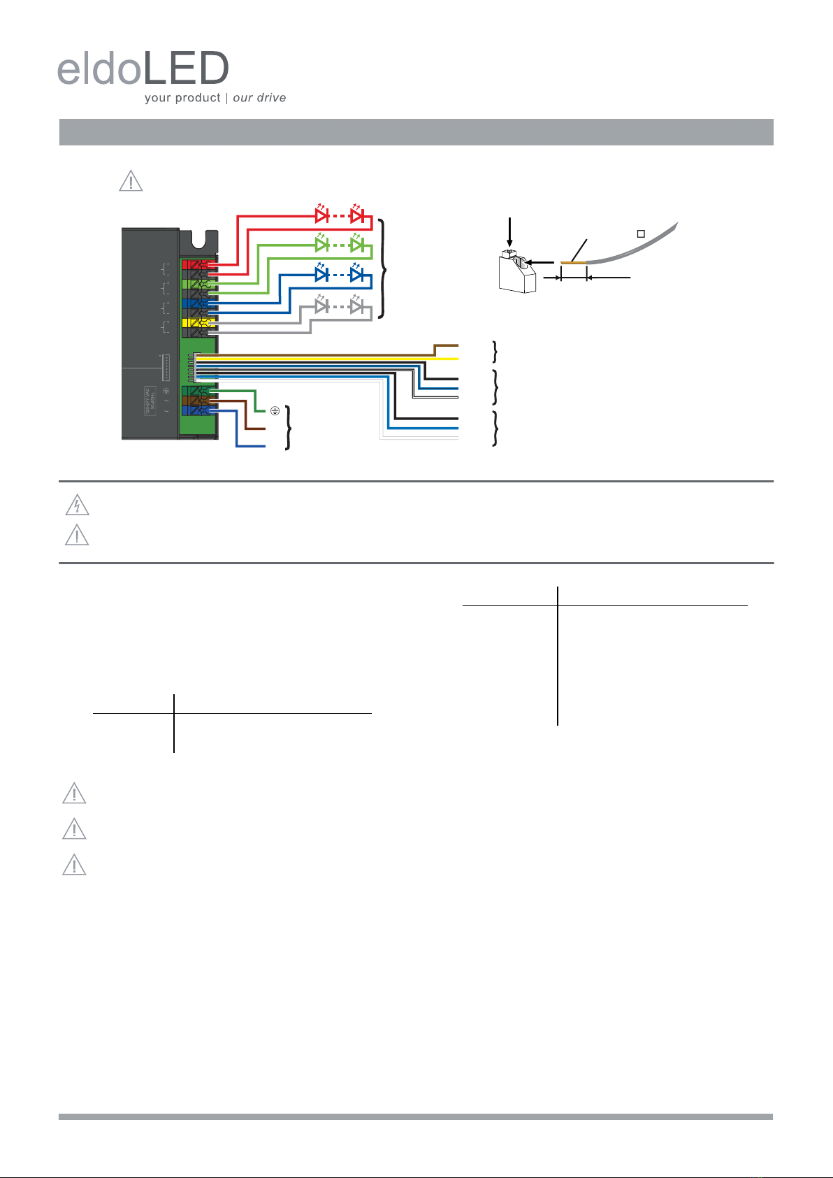
Wiring diagram POWERdrive 561/S, 561/A (PW0561S1, PW0561A1)
WARNING: Risk of electrical shock. May result in serious injury or death. Disconnect power before servicing or installing.
CAUTION: The device may only be connected and installed by a qualified electrician. All applicable regulations, legislation and build-
ing codes must be observed. Incorrect installation of the device can cause irreparable damage to the device and the connected LEDs.
LED outputs
R(ed) represents channel 1, G(reen) represents channel 2, B(lue) rep-
resents channel 3, and W(hite) represents channel 4. The default
group colour allocation can be changed using the TOOLbox pro and
freely available FluxTool application.
Maximum wiring distance at full load (from LED driver to LED load):
LEDcode/NTC
The LEDcode/NTC interface allows connection of a 47kΩNTC therm-
istor for closed loop thermal control. The NTC throttle temperature is
programmable through the freely available FluxTool software (see
“Configuring your driver over DMX in”).
DMX in/DMX out
Connect the network cable’s DMX+, DMX- and DMX shielding wires
to the corresponding pin or wire on the LED driver.
For LED drivers that feature the WH0081S1 wiring harness, the wire
colors on the harness and corresponding colors in a CAT 5 cable are
listed in the following table.
The WH0081S1 wiring harness can be ordered from eldoLED.
Alternatively, if you wish to use a proprietary solution, the following
molex parts should be used: 1x wire-to-board housing 87439-0800
and 8x crimp terminal 87421-0000.
Configuring your driver over DMX in
Download the FluxTool software from your eldoLED driver’s product
web page and connect a TOOLbox pro to DMX in to configure your
driver. You can configure:
• various DMX parameters
• dimming curve
• minimum dimming level
• NTC throttle temperature
• LED drive current per output, from 200mA-1,050mA in 1mA steps
120-277V AC
The driver has been designed for use with universal mains voltage in-
put (120-277V AC, 50/60Hz), and for use with DC input (120-250V, as
used in emergency lighting).
AWG value 20 19 18 17 16
Distance (m) 14 18 22 28 36
Distance (ft) 46 59 72 92 118
Please observe voltage drop over long cable lengths.
Longer cable lengths increase EMI susceptibility.
For POWERdrive 561/A it is recommended to use shielded
multi-core wires between LED driver and LED engine. Prop-
erly connect shield to ground on both sides.
Wiring harness CAT5 cable
DMX out shield black brown
DMX out - black/blue orange
DMX out + black/white orange/white
DMX in shield black brown
DMX in - blue orange
DMX in + white orange/white
120-277 VAC
L
N
4 LED outputs
4 control channels
2
1
9 mm
0.35 inch
Solid or stranded copper wires only.
0.5-1.5 mm2
AWG 20-16
LED output 1
LED output 2
LED output 3
LED output 4
LEDcode/NTC
DMX out
DMX in
shield
-
+
shield
-
+
-
+

eldoLED B.V. Science Park Eindhoven 5125 5692 ED Son The Netherlands T +31 40 7820400 [email protected]
Wiring diagram POWERdrive 561/S, 561/A (PW0561S1, PW0561A1)
Connecting 3 LED groups
Connecting 2 LED groups
Connecting 1 LED group
This manual suits for next models
3
Other eldoLED Control Unit manuals


Popular Control Unit manuals by other brands

Festo
Festo Compact Performance CP-FB6-E Brief description

Elo TouchSystems
Elo TouchSystems DMS-SA19P-EXTME Quick installation guide

JS Automation
JS Automation MPC3034A user manual

JAUDT
JAUDT SW GII 6406 Series Translation of the original operating instructions

Spektrum
Spektrum Air Module System manual

BOC Edwards
BOC Edwards Q Series instruction manual

KHADAS
KHADAS BT Magic quick start

Etherma
Etherma eNEXHO-IL Assembly and operating instructions

PMFoundations
PMFoundations Attenuverter Assembly guide

GEA
GEA VARIVENT Operating instruction

Walther Systemtechnik
Walther Systemtechnik VMS-05 Assembly instructions

Altronix
Altronix LINQ8PD Installation and programming manual


