TLV SS1VG User manual

Free Float Drain Trap SS1VG
Thank you for purchasing the Free Float Drain Trap for air
and inert gases.
This product has been thoroughly inspected before being shipped
from the factory. When the product is delivered, before doing
anything else, check the specifications and external appearance to
make sure nothing is out of the ordinary. Before beginning installation
or maintenance, please read this manual to ensure correct usage of
the product.
This instruction manual is needed not only for installation, but for subsequent
troubleshooting. Please keep it in a safe place for future reference.
The contents of this manual are subject to change without notice.
1. Safety Considerations
DO NOT use for toxic, flammable or otherwise hazardous fluids. This
product is a drain trap that discharges condensate from air or inert gas
systems. Use only for air or inert gas. This product is for intended use
only. Improper use may result in such hazards as damage to the
product or malfunctions that may lead to serious accidents.
WARNING
NEVER apply direct heat to the float. The float may explode due to
increased internal pressure, causing accidents leading to serious injury
or damage to property and equipment.
WARNING
Install properly and DO NOT use this product outside the recommended
operating pressure, temperature and other specification ranges.
Improper use may result in such hazards as damage to the product or
malfunctions which may lead to serious accidents. Local regulations
may restrict the use of this product to below the conditions quoted.
CAUTION
DO NOT use this product in excess of the maximum operating pressure
differential; such use could make discharge impossible (blocked).
CAUTION
Take measures to prevent people from coming into direct contact with
product outlets. Failure to do so may result in burns or other injury from
the discharge of fluids.
CAUTION
When disassembling or removing the product, wait until the internal
pressure equals atmospheric pressure and the surface of the product
has cooled to room temperature. Disassembling or removing the
product when it is hot or under pressure may lead to discharge of fluids,
causing burns, other injuries or damage.
CAUTION
Be sure to use only the recommended components when repairing the
product, and NEVER attempt to modify the product in any way. Failure to
observe these precautions may result in damage to the product or burns
or other injury due to malfunction or the discharge of fluids.
CAUTION
Use only under conditions in which no freeze-up will occur. Freezing
may damage the product, leading to fluid discharge, which may cause
burns or other injury.
CAUTION
Installation, inspection, maintenance, repairs, disassembly, adjustment
and valve opening/closing should be carried out only by trained
maintenance personnel.
CAUTION
2. Specifications
Refer to the product nameplate for detailed specifications.
* Maximum allowable pressure
(PMA) and maximum allowable
temperature (TMA) are
PRESSURE SHELL DESIGN
CONDITIONS (NOT
OPERATING CONDITIONS)
** Valve No. is displayed for
products with options. This item
is omitted from the nameplate
when there are no options.
Minimum Required Condensate Load: For SS1VG-M with a metal valve seat, a minimum
required condensate load of 0.5 kg/h (1 lb/h) is necessary to maintain a liquid seal. There is a
chance of air/gas leak if the condensate load falls below this rate.
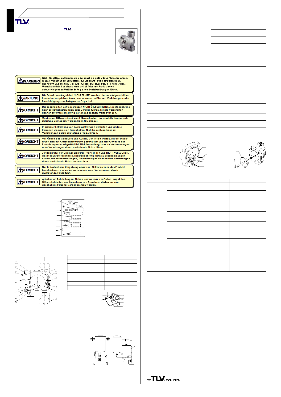
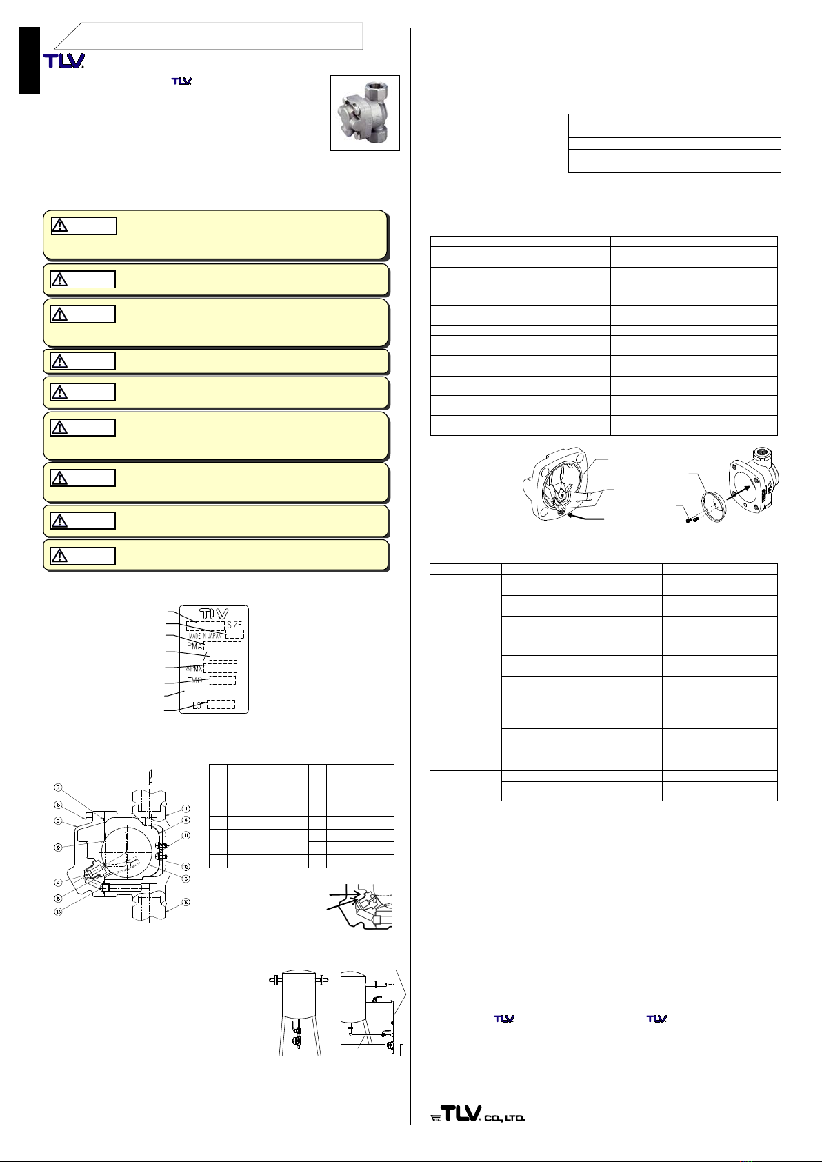
3. Configuration
No.
Name
No.
Name
1
Body
7
Cover Gasket
2
Cover
8
Cover Bolt
3
Float
9
Nameplate
4
Valve Seat (Orifice)
10
Flange
5 Valve Seat (Orifice)
Gasket
11
Screw
12
Spring Washer
6
Screen
13
Connector
4. Proper Installation
1.
Before installation, be sure to remove all protective seals.
2.
Before installing the product, open the inlet valve and
blow out the piping to remove any piping scraps,
dirt and oil. Close the inlet valve after blowdown.
3.Install the product so the arrow on the body is
pointing in the direction of flow.
4.To prevent air binding, inlet piping must be
straight, vertical, as short as possible and with a
minimum nominal diameter of 15 mm (1/2in). If a
length of horizontal piping between the equipment
and the product is unavoidable, the horizontal
piping must be kept as short as possible. If it
exceeds 200 mm (8 in), a pressure-balancing line must be installed (see right).
5.The product must be installed vertically, inclined no more than 5° horizontally and
front-to-back.
6.Install a condensate outlet valve and outlet piping.
7.Open the inlet and outlet valves, make sure that the product functions properly.
5. Inspection and Maintenance
Operational Check: A visual inspection of the following items should be done on a
daily basis to determine whether the product is operating properly or has failed.
Periodically (at least biannually) the operation should also be checked by using
diagnostic equipment, such as a stethoscope or thermometer.
If the product should fail, it may cause damage to piping and equipment, resulting in
faulty or low quality products or losses due to air or gas leakage.
When parts have been
removed, or during periodic
inspections, use the table to
the right to inspect the parts
and replace any that are
found to be defective.
6. Disassembly / Reassembly
Use the following procedures to remove components. Use the same procedures in
reverse to reassemble. If drawings or other special documentation were supplied for the
product, any torque given there takes precedence over values shown here.
Part
During Disassembly
During Reassembly
Cover Bolt
Remove with a 17 mm (21⁄
32
in)
socket wrench
Coat threads with anti-seize; tighten to a
torque of 45 N⋅m (33 lbf⋅ft)
Cover
Remove; take care to prevent
any damage to the float, which
may fall out when the cover is
removed
Make sure there are no pieces of the old
gasket left on the sealing surfaces, then
reattach; be careful not to bend the float
guides (Fig. A)
Float
Remove being careful not to
scratch the polished surface
Place inside body, being careful not to
scratch or misshape
Connector
Remove
Insert into hole in cover
Cover Gasket
Remove gasket and clean
sealing surfaces
Replace with a new gasket if warped or
damaged, do not apply anti-seize
Valve Seat
Remove with a 13 mm (1/
2
in)
socket wrench
Coat threads with anti-seize; tighten to a
torque of 15 N⋅m (11 lbf⋅ft)
Valve Seat
Gasket
Remove gasket and clean
sealing surfaces
Replace with a new gasket if warped or
damaged, apply anti-seize
Screw &
Washer
Remove with a Philips
screwdriver
Tighten to a torque of 0.3 N⋅m (0.22 lbf⋅ft)
Screen
Remove without bending
Insert the screen with the proper orientation,
aligning screw holes (Fig. B)
(1 N⋅m ≈10 kg⋅cm)
Figure A
NOTE
: Do not change
the position of the
float guides. Tight
sealing cannot be
guaranteed if the float
guides have been
moved out of position.
Figure B
7. Troubleshooting
When the product fails to operate properly, use the following table to locate the cause.
Problem
Cause
Remedy
No condensate is
discharged
(blocked) or
discharge is poor
The float is damaged or filled with
condensate
Replace with new float
The valve seat opening, screen or piping
are clogged with rust and scale
Clean parts
The trap operating pressure exceeds the
maximum specified pressure, or there is
insufficient pressure differential between
the trap inlet and outlet
Compare specifications and
actual operating conditions
Air binding has occurred
Correct the installation
(see “Proper Installation”)
The specific gravity of the fluid is not
suitable for this product
Consult TLV
Air/gas is
discharged or
leaks from the
outlet*
(blowing)
(air/gas leakage)
Rust and scale have built-up around the
valve seat or beneath the float
Clean parts
The valve seat is scratched or damaged
Replace with new valve seat
The float is deformed or has a build-up
Clean or replace float
Improper installation orientation
Correct the installation
There is excessive trap vibration
Lengthen inlet piping and
fasten securely
Air/gas is leaking
from a place other
than the outlet
Gasket(s) are deteriorated or damaged
Replace with new gasket(s)
Improper tightening torques were used
Tighten to the proper torque
* SS1VG-M with metal valve seat requires a minimum condensate load of 0.5 kg/h (1 lb/h) to
prevent any air/gas leak
8. Product Warranty
1. Warranty Period: One year following product delivery.
2. TLV CO., LTD. warrants this product to the original purchaser to be free from
defective materials and workmanship. Under this warranty, the product will be
repaired or replaced at our option, without charge for parts or labor.
3. This product warranty will not apply to cosmetic defects, nor to any product whose
exterior has been damaged or defaced; nor does it apply in the following cases:
1) Malfunctions due to improper installation, use, handling, etc., by other than TLV
CO., LTD. authorized service representatives.
2) Malfunctions due to dirt, scale, rust, etc.
3) Malfunctions due to improper disassembly and reassembly, or inadequate inspection
and maintenance by other than TLV CO., LTD. authorized service representatives.
4) Malfunctions due to disasters or forces of nature.
5) Accidents or malfunctions due to any other cause beyond the control of TLV CO., LTD.
4. Under no circumstances will TLV CO., LTD. be liable for consequential economic
loss or damage or consequential damage to property.
For Service or Technical Assistance:
Contact your representative or your regional office.
Manufacturer:
881 Nagasuna, Noguchi, Kakogawa, Hyogo, 675-8511 Japan
Tel: [81]-(0)79-422-1122 Fax: [81]-(0)79-422-0112
Rev. 3/2017 (T)
SS1VG-M
(with metal valve seat)
English
Nominal Diameter
Production Lot No.
Valve No.**
Maximum Allowable Pressure*
Max. Allowable Temperature*
Max. Operating Temperature
Model
Maximum Differential Pressure
Screw & Washer
Screen
Float Guides
Connector
Cover
Gasket
Gaskets: check for warping or damage
Screen: check for clogging, corrosion or damage
Valve Seat: check for clogging, warping or scratches
Float: check for scratches, dents or water inside the float
Body, Cover: check for damage or build-up inside
Standard Requiring
Balancing Line
Pressure-balancing Line
Inlet Piping
INSTRUCTION MANUAL
Keep this manual in a safe place for future reference
SS1VG-R
(with rubber valve seat)
④
⑤

EINBAU- UND BETRIEBSANLEITUNG
Entwässerer SS1VG
Wir danken Ihnen für den Kauf des Entwässerers für Druckluft
und Inertgase.Dieses Produkt wurde nach Fertigstellung sorgfältig
geprüft und verließ unsere Fabrik vollständig und fehlerfrei. Wir
empfehlen jedoch, nach Erhalt den einwandfreien Zustand zu
überprüfen und die Spezifikation mit Ihren Bestellunterlagen zu
vergleichen. Bei Unstimmigkeiten benachrichtigen Sie uns bitte
umgehend. Lesen Sie die Anleitung sorgfältig durch, um den korrekten
Gebrauch dieses Produkts sicherzustellen.
Diese Anleitung wird für den Einbau und später für Wartung und Reparatur benötigt.
Daher sollte sie an einer leicht zugänglichen Stelle aufbewahrt werden.
Änderungen dieser Einbau- und Betriebsanleitung vorbehalten.
1. Sicherheitshinweise
2. Technische Daten
Die Technischen Daten stehen auf dem Typenschild
* Maximal zulässiger Druck (PMA)
und maximal zulässige
Temperatur (TMA) sind
AUSLEGUNGSDATEN (NICHT
BETRIEBSDATEN).
** Die Ventil-Nr. wird angegeben bei
Typen mit Optionen. Bei Typen
ohne Optionen bleibt diese Stelle
frei.
Mindestkondensatmenge: Für SS1VG-M mit Metall-Ventilsitz ist eine Mindestkondensatmenge
von 0,5 kg/h erforderlich, um eine Flüssigkeitsvorlage für dichten Abschluss zu erhalten. Ohne
diese Kondensatmenge besteht die Möglichkeit von Luft- oder Gas-Leckage.
3. Aufbau
Nr.
Bauteil
Nr.
Bauteil
1
Gehäuse
8
Gehäuseschraube
2
Gehäusedeckel
9
Typenschild
3
Schwimmerkugel
10
Flansch
4
Ventilsitz
11
Schraube
5
Ventilsitzdichtung
12
Federring
6
Schmutzsieb
13 Verbindungshülse
7
Gehäusedichtung
4. Einbauhinweise
1. Vor dem Einbau die Transport-Schutzkappen entfernen.
2. Vor dem Einbau das Einlassventil öffnen und die Leitung durchblasen, um Öl und
Verschmutzungen zu entfernen. Danach das Ventil schließen.
3. Den Produkt mit dem Pfeil auf dem Gehäuse in Durchflussrichtung einbauen.
4. Zur Vermeidung von Luftabschluss die Einlass-
leitung geradlinig, vertikal und so kurz wie möglich
und mit mindestens 15 mm Durchmesser verle-
gen. Falls ein Stück horizontaler Leitung zwischen
der Anlage und dem Produkt unvermeidbar ist,
sollte sie so kurz wie möglich verlegt werden. Ist
sie länger als 200 mm, muss eine Druck-
ausgleichleitung installiert werden (siehe rechts).
5. Den Produkt vertikal und innerhalb einer
Schräglagentoleranz von 5° in horizontaler und
vertikaler Richtung einbauen.
6. Am Auslass ein Absperrventil und eine Kondensatleitung anbringen.
7. Einlass- und Auslassventile öffnen und prüfen, ob der Produkt wie vorgesehen,
arbeitet.
5. Inspektion und Wartung
Funktionsprüfung Visuelle Inspektionen sollten täglich erfolgen, um festzustellen, ob
der Produkt ordnungsgemäß arbeitet, oder beschädigt ist. Mindestens zweimal pro Jahr
oder, je nach Betriebsweise in kürzeren Zeitabständen wird die Überprüfung mit
Messgeräten, z. B. Stethoskop oder Thermometer empfohlen.
Fehlerhafte Produkt können Beschädi
gungen an Rohrleitungen und Anlagen
verursachen, was zur Verschlechterung
der Produktqualität führen kann.
Die möglichen Fehler entsprechend der
Tabelle rechts suchen und überprüfen.
Dann die fehlerhaften Teile ersetzen.
6. Ausbau / Einbau
Ausbau von Teilen in dieser Reihenfolge vornehmen, den Einbau in umgekehrter.
Bauteil
Ausbau
Einbau
Gehäuse-
schraube
Mit 17 mm Steckschlüssel
abschrauben
Gewinde mit Schmiermittel bestreichen
und auf 45 N⋅m anziehen
Gehäuse-
deckel
Vorsichtig herausnehmen, dabei
auf die Schwimmerkugel achten,
die herausfallen und beschädigt
werden könnte
Vor dem Aufsetzen alte Dichtungsreste
sorgfältig entfernen; beim Aufsetzen des
Deckels nicht die Kugelauflagen verbiegen
(Abb. A)
Schwimmer-
kugel
Herausheben, feingeschliffene
Oberfläche nicht zerkratzen
Einsetzen ohne zu zerkratzen oder
verbeulen
Verbin-
dungshülse
Herausziehen
In Gehäusedeckel einsetzen
Gehäuse-
dichtung
Dichtung entfernen und
Dichtflächen reinigen
Dichtung erneuern, falls verformt oder
beschädigt, nicht mit Schmiermittel
bestreichen
Ventilsitz
Mit 13 mm Steckschlüssel
abschrauben
Gewinde mit Schmiermittel bestreichen
und auf 15 N⋅m anziehen
Ventilsitz-
dichtung
Dichtung entfernen und
Dichtflächen reinigen
Dichtung erneuern, falls verformt oder
beschädigt, mit Schmiermittel bestreichen
Schrauben &
Federringe
Mit Schraubenzieher
abschrauben
Gewinde mit Schmiermittel bestreichen
und auf 0,3 N⋅m anziehen
Schmutzsieb
Abnehmen, ohne zu verbiegen
Schmutzsieb mit den Schraubenlöchern
übereinstimmend einsetzen (Abb. B)
Abb. A
Vorsicht: Die
Kugelauflagen nicht
verstellen. Dichter
Abschluss kann sonst
nicht gewährleistet
werden.
Abb. B
7. Fehlersuche
Falls der Produkt nicht zufriedenstellend arbeitet, nach dieser Fehlerliste vorgehen.
Symptom
Ursachen
Gegenmaßnahmen
Kondensat
läuft nicht ab
(blockiert),
oder Ableitung
ist ungenügend
Die Schwimmerkugel ist beschädigt, oder voll
Wasser
Schwimmerkugel ersetzen
Ventilsitz, Schmutzsieb oder Rohrleitungen sind
verstopft mit Schmutzablagerungen oder Rost
Reinigen
Der Betriebsdruck des Entwässerers übersteigt
den maximal zulässigen Druck oder der
Differenzdruck zwischen Einlass und Auslass ist
zu niedrig
Prüfen, ob die Ausleg-
ungsdaten mit den wirk-
lichen Betriebsdaten über-
einstimmen und ändern
Luftabschluss ist eingetreten
Rohrleitungssystem prüfen
und ändern
(siehe Einbauhinweise)
Der Entwässerer ist nicht geeignet für das
Spezifische Gewicht des Mediums
TLV konsultieren
Luft- oder
Gasverlust
über die
Kondensat-
auslassleitung
(Entwässerer
bläst)
(Luft-/Gas-
Leckage)
Rost und Schmutz am Ventilsitz oder unter der
Schwimmerkugel
Reinigen
Der Ventilsitz ist zerkratzt oder beschädigt
Ventilsitz erneuern
Die Schwimmerkugel ist verformt oder äußerlich
verschmutzt
Reinigen oder ersetzen
Der Entwässerer ist in zu großer Schräglage
eingebaut
Innerhalb der Schräg-
lagentoleranz einbauen
Der Entwässerer vibriert
Einlassleitung verlängern
und besser unterstützen
Luft-/Gas-
Leckage aus
dem Gehäuse
Dichtungen sind abgenutzt oder beschädigt
Dichtungen ersetzen
Das Anzugsmoment der Gehäuseschrauben ist
zu gering
Mit richtigem Anzugs-
moment anziehen
* SS1VG-M Metall-Ventilsitz erfordert eine Mindestkondensatmenge von 0,5 kg/h um Luft-
/Gas-Leckagen zu vermeiden.
8. Garantie
1. Garantiezeit: Ein Jahr nach Lieferung.
2. Falls das Produkt innerhalb der Garantiezeit aus Gründen die TLV CO., LTD. zu
vertreten hat, nicht der Spezifikation entsprechend arbeitet, oder Fehler an Material
oder Verarbeitung aufweist, wird es kostenlos ersetzt oder repariert.
3. Von der Produktgarantie ausgenommen sind kosmetische Mängel sowie
Beschädigungen des Produktäußeren. Die Garantie erlischt außerdem in den
folgenden Fällen:
1)Schäden, die durch falschen Einbau oder falsche Bedienung hervorgerufen werden.
2)Schäden, die durch Verschmutzungen, Ablagerungen oder Korrosion usw. auftreten.
3)Schäden, die durch falsches Auseinandernehmen und Zusammenbau, oder
ungenügende Inspektion und Wartung entstehen.
4)Schäden verursacht durch Naturkatastrophen und Unglücksfälle.
5)Unglücksfälle und Schäden aus anderen Gründen, die von TLV CO., LTD. nicht zu
vertreten sind.
4. TLV CO., LTD. haftet nicht für Folgeschäden.
Für Wartung und Technische Beratung wenden Sie sich bitte an die TLV Vertretungen
oder an die regionalen TLV Niederlassungen.
Hersteller:
881 Nagasuna, Noguchi, Kakogawa, Hyogo, 675-8511 Japan
Tel: [81]-(0)79-422-1122 Fax: [81]-(0)79-422-0112
Rev. 3/2017 (T)
Deutsch
Typ
SS1VG-M
(Metallsitz)
Schmutzsieb
Kugelauflagen
Verbindungshülse
Gehäusedeckel
Schraube &
Federring
Dichtungen: Verformung und Kratzer
Ventilsitz: Verformungund Beschädigung
Schmutzsieb: Verstopfung,
Ablagerungen und Beschädigung
Schwimmerkugel: Kratzer, Verbeulung,
Wasser in der Schwimmerkugel
Gehäuse, Deckel: Beschädigung,
Ablagerungen und Verschmutzung innen
Standard Druckausgleich-
leitung erforderlich
Größe/DN
Fertigungslos-
Nr.
Ventil-
Nr.**
Maximal zulässiger Druck *
Maximal zulässige Temperatur *
Maximale Betriebstemperatur
Maximaler Differenzdruck
④
⑤
SS1VG-R
(Gummisitz)
Druckausgleich-
leitung
Einlassleitung
Table of contents
Languages:
Other TLV Control Unit manuals
Popular Control Unit manuals by other brands

WEG
WEG SSW900-CPDP-N Installation, configuration and operations guide

Sunrise telecom
Sunrise telecom SSxDSL-5M user manual

Allen-Bradley
Allen-Bradley 1771-OW installation guide

Itho Daalderop
Itho Daalderop I2C manual

Motorola
Motorola MVME224A Series Operation and Users Manual

KSB
KSB BOAX-B Installation & operating manual