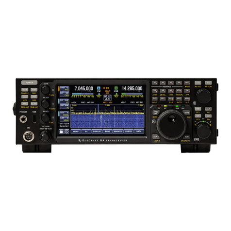
ELECRAFT K4 User manual

ELECRAFT K4 OPERATING MANUAL
Rev C9
Table of Contents
I. INTRODUCTION
USING THE BUILT-IN OPERATING MANUAL
K4 TRANSCEIVER OVERVIEW
INSTALLATION INSTRUCTIONS
REAR PANEL CONNECTIONS
II. FRONT PANEL REFERENCE
USING TAP, HOLD, and TOUCH CONTROLS
FRONT PANEL OVERVIEW
LEFT-SIDE CONTROLS
MULTI-FUNCTION CONTROLS
LCD SCREEN AND TOUCH CONTROLS
VFOs AND RIGHT-SIDE CONTROLS
III. OPERATING INSTRUCTIONS
PRIMARY FUNCTIONS

BAND SELECTION
ANTENNA SELECTION
OPERATING MODES
RECEIVER SETTINGS
TRANSMITTER SETTINGS
TX AND RX METERING
PANADAPTER
DUAL RECEIVE
HDR RECEIVE (K4HD)
AUDIO EFFECTS (AFX)
DIGITAL VOICE RECORDER (DVR)
USING THE STATUS DISPLAY
FREQUENCY MEMORIES
USING SPLIT
INTERNAL & EXTERNAL TRANSVERTERS
REMOTE CONTROL
MACRO PROGRAMMING
RTTY CONFIGURATION
FT8 / JT / ETC. CONFIGURATION
IV. MENU LISTING
V. TROUBLESHOOTING

_________________________________________________
I. INTRODUCTION
USING THE BUILT-IN OPERATING MANUAL
This operating manual is a compact reference to all K4 controls, connectors, display elements, and
menu entries. It also provides context-sensitive help during operation.
Please refer to the Elecraft K4 Owner's Manual for more detailed instructions on all topics. At
minimum, please read the fully illustrated short-form manual, Introduction to the Elecraft K4, to
become familiar with control and connector locations.
To view the built-in operating manual, tap the button labeled "?" at the lower left-hand corner of the
LCD screen:
For help with the most recent controls used, tap the LAST CTRL button one or more times.
To scroll through text, rotate the VFO A knob. Navigate by clicking on underlined links and using the
forward/backwards buttons. Tap the table of contents button to return to the top.
To search by topic, tap the magnifying glass button. If there's more than one match, the up/down
arrow buttons will navigate among them. Tap the magnifying glass button again to exit match
navigation and return to scrolling.
For a full-screen version of the operating manual, tap the resize button.

Key to Text Styles
Important cautions are shown in red.
The following text conventions are used when referring to controls:
[Physical Switch] <Touch Control> {Knob}
Switch, touch, and knob controls are shown in white for tap,yellow for hold, as on the transceiver
itself.
Many LCD labels, icons and graphics also function as touch controls. Those which appear in the form
of labeled switches are referred to as 'buttons' to differentiate them from physical switches.
MENU ENTRIES are shown as MENU:Name, e.g. MENU:LCD Brightness. For a full list of menu
entries, see IV. MENU LISTING.
** Indicates a feature that is still in development.
K4 TRANSCEIVER OVERVIEW
The K4 is a high-performance, direct-sampling software-defined radio (SDR). It covers the 160 ~ 6 m
bands, with continuous receive from 100 kHz ~ 54 MHz. 10 W and 100 W models are available. It can
be used with internal or external transverters to cover bands from VHF up.
Among the K4's notable features: A large color touch screen, as well as support for an external
monitor; extensive, easy to use controls; rich analog and digital connectivity; dual receive; built-in
data modes, and wide range antenna tuner. In addition to its extensive front panel controls, the K4
has full mouse support, and can also be controlled by an Elecraft K-Pod.
The K4's compact size and weight, combined with 11-15 VDC operation and low current drain, make
it suitable for field, travel, or home station use.
Since the K4 is an SDR, Elecraft can provide updates to its signal processing algorithms with

software changes rather than by adding new hardware. This ensures that the K4 can take advantage
of new modes, bands, or other features in the future. Since it uses direct sampling, signals are
digitized right at the receiver inputs, and the transmitter's amplifier chain is also driven by a digitized
signal. Older SDR architectures digitized signals at a low intermediate frequency (IF), resulting in
poor suppressions of down-conversion or up-conversion images.
There are three models: the basic K4, with one set of receive filters and one analog-to-digital
converter (ADC); the K4D, with a second set of receive filters and a second ADC; and the K4HD,
which adds a superheterodyne front end that can be enabled as needed to provide even greater
dynamic range. The superhet module uses high-performance, narrow-band crystal filters such as
those used in the Elecraft K3S.
Even the basic K4 provides simultaneous dual receive on the same or different bands/modes.
However, the K4D and K4HD models include an additional receiver module (KRX4) with a second set
of band-pass filters, improving signal handling during dual-receive operation on different bands. The
second receiver also permits diversity reception, i.e., the use of different antennas for the two
receivers to counteract fading (QSB).
A basic K4 can be upgraded to a K4D by installing the KRX4 option. Similarly, a K4D can be
upgraded to a K4HD by installing a KHDR4 module. Other internal options and external accessories
are applicable to all three models, including a wide-range ATU (KAT4), MH4 microphone, SP4
external speaker (1 or 2). For further information, visit www.elecraft.com.
INSTALLATION INSTRUCTIONS
CAUTION: Ground your K4 properly before operation using the provided wing nut ("GND"). For
suggestions, see www.arrl.org/grounding.
Even though the K4 has extensive internal protective circuitry, external protection against lightning
strikes is strongly recommended, especially in lightning-prone areas.
During storms and when the station is not in use for an extended period, disconnect ALL equipment
from the K4, including antennas, power supply, routers or hubs, and computers. Ethernet, USB, and
RS232 cables are a frequent source of damaging surge voltages.
Orientation and Air Flow
Provide at least 1" of free space both above and behind the transceiver. Ventilation holes on the
bottom and left sides must also not be blocked.
Using the Tilt Stand
If the K4 is placed on a desk or table, deployment of the tilt stand is strongly recommended to
facilitate easier interaction with the touch screen. This will also improve display viewing angle.
Removing LCD Protective Film
Carefully peel the protective film off the LCD. There's a small plastic tab at the upper right corner for
this purpose. If the film is left on, it will degrade the appearance of LCD graphics as well as touch
screen performance.
Power Supply
Use the shortest practical length of power cable, with heavy wire gauge to minimize voltage drop. The
supplied power cable includes fuses in both legs. The supplied cable is #12 AWG, and the fuses in
each leg are rated at 25 amps.
A power supply voltage of 13.8 to 14.2 V is preferred. For 100 W use, a 30 amp supply is
recommended. For 10 W use, a 5 amp supply will suffice. NOTE: If use of a switching supply results
in low-pitched repetitive noise or other artifacts when monitoring your K4's signal in another receiver,
consider using a well-regulated and filtered linear supply.
Minimum supply voltage is 11.0 V. The K4 will automatically reduce power output if the supply voltage
is too low to maintain good IMD performance at the selected RF output level.

Interfacing to Station Equipment
Refer to the REAR PANEL CONNECTIONS section, below, for descriptions of all connectors and
interfacing requirements. At minimum you'll need to connect a power supply, antenna, and station
ground.
Getting Started
Once your K4 is installed and you're ready to operate, you can get started in one of two ways: (1)
read the FRONT PANEL REFERENCE section to learn about each of the controls, or (2) jump to the
OPERATING INSTRUCTIONS section, which is more procedural in nature.
Software Updates
An internet connection is the preferred way to do software updates. To initiate an update, tap primary
function button <Fn>, then hold <UPDATE>. Once the software update screen is displayed, tap the
<?> button for detailed instructions on how to update software and read release notes.
REAR PANEL CONNECTIONS
Rear panel connections are briefly described below, from left to right and top to bottom as viewed
from the back. The information provided in this operating manual is limited; refer to the K4 owner's
manual for more details.
ANT 1, ANT 2, ANT 3
These are the HF/6 m transmit-receive antenna jacks. If an ATU is not installed, only the ANT 1 jack
will be present. Also see ANTENNA SELECTION.
ANT 4
Antenna jack for use with an internal transverter, if applicable. If no transverter is installed, the jack

will not be present.
12 VDC IN
Anderson Power Pole (APP) connectors for 11-15 V DC supply. 30 amp supply recommended for 100
W use. See INSTALLATION INSTRUCTIONS for cable and fusing requirements.
12 VDC OUT
12 V switched output for use with accessories, 1.5 amps max (protected by self-resetting fuse).
GROUND (Wing Nut)
For attachment of station ground. See INSTALLATION INSTRUCTIONS.
TX SMPL IN
If transmit IMD optimization** is enabled for use with an external linear amplifier (such as the Elecraft
KPA1500), connect its transmit output sample port to TX SMPL IN. Refer to the owner's manual for
signal level and calibration details.
Transmit IMD optimization can also be enabled for use with the K4's internal amplifier stages.
XVTR IF IN / RX ANT 2
This jack can be used as a general-purpose receive antenna, or for connection to an external
transverter (in conjunction with XVTR IF OUT). See TX AND RX ANTENNA SELECTION .
XVTR IF OUT
This can be used as the output drive signal for an external transverter.
RX ANT 1 IN
General-purpose receive antenna input. See ANTENNA SELECTION.

RX ANT OUT
When the RX ANT OUT jack is active, its signal can be used along with RX ANT 1 IN or XVTR IF
IN/RX ANT 2 IN to provide a path through an external band-pass filter, splitter, etc. The RX ANT OUT
signal is obtained from the transmit antenna path, so it passes through the ATU (if applicable) as well
as the transmit low-pass filters and T/R switch.
RX ANT OUT is only active if the main and sub receivers are both configured to use receive-only
antennas. See Using RX ANT OUT.
ETHERNET
Connect to station router or modem. Compatible with 10/100/1000 megabit rates. A high quality
shielded cable is strongly recommended; refer to Elecraft web site for available cable(s).
Ethernet connectivity is preferred for software updates and remote control applications, such as our
Virtual K4 program (see REMOTE CONTROL).
Note: If you have any difficulty with software updates, tap the "?" button from within the UPDATE
function. Also see TROUBLESHOOTING.
USB
The rear panel has two type A USB jacks and one of type B, labeled "PC". There is an additional type
A jack on the front panel. Any of the type A jacks may be used with a keyboard, mouse, memory
device, or Elecraft K-Pod. Wireless adapters may be used.
The type B USB jack provides two virtual COM ports, referred to in this manual as USB-PC1 and
USB-PC2, that can be used for radio control and soundcard I/O (digital version of LINE IN / LINE
OUT). LINE OUT is stereo; LINE IN is mono. Connect the cable to any USB-A jack on a host
computer or hub.
To set the baud rates for these ports, use the Serial USB-PCn: Baud Rate menu entries. Refer to
software application manuals for port setup instructions. (Plugging in new devices, including the K4,

may alter COM port assignments.)
To use the RTS and DTR signals of the USB-PCn ports for transmit functions (PTT, KEY, or FSK
select), or to configure them for Auto-Info frequency data output (AI), use the associated Serial
USB-PCn menu entries.
To set up these ports for soundcard receive audio, first tap the <MAIN RX> function button, then tap
<LINE OUT>. For soundcard transmit audio setup, tap <TX>, then <LINE IN>. Also see TX button
description.
A third COM port is also available for remote control/data; see RS-232, below.
VIDEO
Connection for an external monitor. The monitor can be configured to show only the panadapter,
which may be configured differently from the panadapter shown on the LCD. See Ext. Monitor
Function and LCD SCREEN AND TOUCH CONTROLS.
REF IN
A 10 MHz reference signal may be connected to this jack. The K4's internal reference oscillator will
lock to this signal when present. Also see ER100 (Error Messages).
LINE IN
This is an analog audio input (nominally 600 ohms) for connection to computers or other station
equipment that supply transmit audio to the K4. An example of this is a software application that
supplies data-mode audio signals, e.g. FT8, RTTY, or PSK31. In voice modes, LINE IN can be used
in lieu of, or in conjunction with, microphone audio; see TX button description.
Most computer software can alternatively provide LINE IN signals from a virtual COM port, eliminating
the need for analog cabling and potentially reducing noise. See description of rear-panel USB
connector, above.

LINE OUT
This is an analog audio output (stereo; nominally 600 ohms) for connection to computers or other
station equipment that obtain receive audio from the K4. An example of this is a software application
that demodulates data-mode audio signals such as FT8, RTTY, or PSK31, as well as CW signals.
Receive audio is always present at both the analog LINE OUT jack and the soundcard output (see
USB). If the sub receiver is turned on, the right channel supplies sub-RX audio. If the sub RX is
turned off, then right-channel audio is identical to left (main RX). Also see MAIN RX button
description.
Most computer software can alternatively accept LINE OUT signals from a virtual com port,
eliminating the need for analog cabling and reducing noise. See description of rear-panel USB
connector, above.
Note: Windows Sound Control Panel does not accurately show sound input level. The correct levels are
shown by WSJT, MMTTY, and other apps.
SPKRS
Left and/or right speaker audio (nominally 4 to 16 ohms). 1 or 2 non-powered speakers such as the
Elecraft SP3 or SP4 may be connected to this jack. Powered speakers may also be used, though
attenuation may be needed between the speaker jack and the external speakers to prevent overdrive.
Plugging in external speaker(s) disconnects the internal speaker.
CAUTION: To avoid possible damage to the second speaker channel, always use a stereo plug, even
when connecting only a single speaker.
If only one external speaker is connected, use the left channel output (tip), and set MENU:Speakers
to 1. As with the internal speaker, a single external speaker will mix main and sub receiver audio.
If two speakers are connected, set MENU:Speakers to 2. Audio is then routed as follows:

• If the sub RX is turned ON, the left speaker output supplies main-RX audio, and the right speaker
output supplies sub-RX audio. (Main/sub audio balance control is in development.)
• If the sub RX is turned OFF, the speaker outputs are identical, unless stereo effects are in use; see
AUDIO EFFECTS (AFX).
PHONES
Connection for rear-panel headphones, in parallel with the front-panel headphones. Requires a 1/8"
(3.5 mm) plug, either mono or stereo. Plugging in headphones disconnects the speaker(s) unless the
Speakers + Phones menu entry is set to Yes.
MIC
Connection for rear-panel microphone. Bias and gain for the rear-panel mic can be set up
independently from the front panel mic. Tap <TX> primary function button, then the <MIC INP> and
<MIC CFG> secondary function buttons.
RS-232
This DE9 connector provides a true-RS232 COM port that can be used for remote control of the K4.
The K4 can also emit Auto-Info (AI) frequency data on this port for use with external devices such as
antenna controllers.
To configure the data rate for this port, set up transmit functions for the RTS and DTR lines (PTT or
KEY), or configure it for auto-info (AI), use the corresponding Serial RS232 menu entries.
PTT IN
RCA jack for use with external PTT controls, e.g. a foot switch or station controller. Pull this input to
ground (0V) to key the transmitter.
Additional PTT sources can be defined using MENU: Serial IO functions for USB-PC1, USB-PC2, and
RS232. The DTR and/or RTS signals from any of these ports can be used in any combination.

KEY OUT
RCA jack that provides a keying output signal for use in keying amplifiers or other station gear. The
signal goes low (0V) when the K4 is keyed by any method.
To configure this output to match the requirements of external equipment, use menu entry TX DLY,
KEY Out to RF Out.
PADDLE
1/4" (6.35 mm) keyer paddle input jack. The dot and dash inputs on this jack activate the K4's built-in
CW keyer.
To set up Iambic keying mode, reverse the dot/dash paddles, or adjust keying weight, tap the <TX>
function button, followed by the <PDL>, <IAMB>, or <WEIGHT> buttons. Applicable modes include
CW, FSK, and PSK.
KEY
1/4" (6.35 mm) keying input jack for use with a hand key, bug, electronic keyer, or other keying
device.
Additional KEY input sources can be defined using MENU: Serial IO functions for USB-PC1,
USB-PC2, and RS232. The DTR and/or RTS signals from any of these ports can be used in any
combination.
ACC
Accessory IO connector (DE15). This connector provides a number of input signals for use in
controlling the K4, as well as outputs for controlling external equipment. The list below summarizes
these functions; refer to the K4 owner's manual for further details.
Pin Description
1 FSK IN (active low); available in FSK mode (also see USB and RS232)

2 AUXBUS in/out; controls Elecraft amps, transverters, and the KRC2
3 BAND1 OUT; BAND0-BAND3 outputs provide 4-bit parallel band indication
4 PTT IN (in parallel with PTT jack as well as mic PTT)
5 Ground
6 DIGOUT0; low-power external transverter select
7 K4 "power on" signal or TX Inhibit input (see TX Inhibit Mode)
8 Power On; pull to ground (0 V) for 0.2 to 1.0 sec to turn K4 on, then release
9 BAND2 OUT; BAND0-BAND3 outputs provide 4-bit parallel band indication
10 KEY OUT LP; low-power keying output (10 mA max)
11 DIGOUT1; per-band/per-antenna output
12 Ground
13 BAND0 OUT; BAND0-BAND3 outputs provide 4-bit parallel band indication
14 BAND3 OUT; BAND0-BAND3 outputs provide 4-bit parallel band indication
15 EXT ALC; negative-going ALC voltage from external amplifier
_________________________________________________
II. FRONT PANEL REFERENCE
This section lists and describes all of the K4's controls and display elements, generally proceeding
from left to right on the front panel.
** Indicates a feature that is still in development.

USING TAP, HOLD, and TOUCH CONTROLS
The following text conventions are used when referring to controls:
[Physical Switch] <Touch Control> {Knob}
All physical and touch controls are described in the FRONT PANEL OVERVIEW section, which
follows.
Using Tap and Hold Switch Functions
Each of the K4's physical switches has both a tap function (white label) and a hold function (yellow
label). A tap is a brief press, while a hold is any press longer than about 1/2 second. For example,
[RATE] is a tap function, while [KHZ] is a hold function of the same physical switch.
Using Touch Controls
The K4's touch screen provides quick, convenient access to the rig's most-used features. Many of the
icons and labels are also touch controls.
Examples:
• You can touch VFO digits to select a tuning rate as an alternative to using the [RATE] and [KHZ]
switches.
• To bring up the mode-select button group, tap the mode identifiers near each VFO display, or tap the
[MODE] physical switch above the VFO A knob.
• To select a receive antenna, tap the antenna name icons for each receiver or use [RX ANT] and
[SUB ANT].
On-screen buttons can have one or two functions. For example, the <LAST CTRL> button in the
operating manual screen has only a white label so it can only be tapped. A yellow label on a button
indicates that a hold function is also available.

Multi-Function Knobs
The three multi-function knobs to the left of the LCD also have built-in pushbutton switches, giving
them tap and hold functions. Tap a knob to select a function to adjust; hold to select an additional
function labeled in yellow below the knob.
Each of the specially shaped LCD buttons associated with the multifunction knobs shows a primary
function (upper label), and a secondary function in yellow italics, accessed by tapping the button a
second time. A knob always controls the parameter associated with the upper label on the selected
button.
FRONT PANEL OVERVIEW
A large (7" diagonal) color LCD forms the heart of the K4's user interface. Most of the screen is
dedicated to either a single panadapter (associated with VFO A or VFO B), or split between dual
panadapters (centered below the VFO A and VFO B displays, respectively). Between the VFOs and
panadapters are the bar graph meters and icons for transmit and receive. Along the bottom edge of
the LCD are the Info button (<?>) and seven primary function buttons (see PRIMARY FUNCTIONS.)
Some LCD elements are color-coded, as follows: orange = TX, blue = main RX, green = sub RX.
(Alternate color schemes may be provided in the future.)
The remaining controls are physical knobs and switches, arranged similarly to that of the Elecraft
K3/K3S transceiver:
• FAR LEFT SIDE: Transmit and antenna-selection controls.
• TO THE LEFT OF THE LCD: Three multi-function knobs, each with two associated touch buttons.
These provide quick access to parametric settings for the current operating mode. Below the
multi-function knobs is a concentric knob controlling main/sub receiver AF gain.
• LCD AND TOUCH CONTROLS: See LCD SCREEN AND TOUCH CONTROLS.

• TO THE RIGHT OF THE LCD: VFO A knob, LED status indicators, and numeric keypad. Keypad
switches each have tap and hold functions. They are organized in three rows: message play (top),
receive functions (middle), and VFO controls (bottom). Surrounding the VFO A knob are four
additional VFO controls including the SUB/DIVERSITY switch.
• FAR RIGHT SIDE: Memory STORE/RCL switches, VFO B knob, and RIT/XIT offset controls. The
latter double as programmable functions PF1-PF4.
Front-Panel Connectors
There are three connectors on the front panel:
MIC
The front mic jack is an Elecraft standard 8-pin type. It is compatible with the Elecraft MH4 and other
K3/K3S-compatible microphones. Bias, gain, and mic PTT/UP/DOWN controls are configured using
<TX> <MIC INP> and <MIC CFG>. For pin connections, refer to the owner's manual.
MH4 Settings (recommended): Preamp=off, Bias=on, Buttons=PTT/UP/DN.
PHONES
1/4" (6.53 mm) front phones jack. Can be used with mono or stereo plugs. Plugging in headphones
disconnects the speaker(s) unless the Speakers + Phones menu entry is set to Yes. It may take up to
3 seconds to for front headphone plug insertion or removal to be detected.
NOTE: Some headphones (e.g. Bose QC35) or other audio devices have a capacitor in series with
their plug. These will not work with the front phones jack unless a resistor (typically 15-51 ohms) is
added in parallel. The front phones jack depends on the transducer providing a resistance path to
ground when inserted.
USB
This is a USB type A jack. Like the two type A jacks on the rear panel, it may be used with a

keyboard, wireless keyboard, USB flash memory device, Elecraft K-Pod, mouse, or mouse
transceiver module.
LEFT-SIDE CONTROLS
The group of switches to the left of the LCD includes transmit and antenna functions and the power
on/off switch.
POWER
Tap [POWER] to turn the K4's power on or off.
NOTE: Always turn the K4 off using its power switch. If you need to turn off the power supply as well,
wait until the K4 has completely powered down. (This may take several seconds. You'll hear a
number of relays turning off.)
TUNE
Tap [TUNE] to enter tune mode at the power level set by the {XMTR} <PWR> knob function. This puts
out a CW signal in any operating mode.
By default the same power output level is used on all bands. To save power level per-band, set
MENU:Per Band Power to On. With this setting, a separate power output level for each band is also
maintained for use with Elecraft KPA-series amplifiers.
TUNE LP
Holding [TUNE LP] uses the power level specified by MENU:TUNE LP (Low power TUNE). This is
intended for use with external amplifiers and antenna tuners that have specific drive power
requirements.

XMIT
Tap [XMIT] to place the K4 in transmit mode. This is the equivalent of holding a mic PTT button or
asserting any of the other PTT lines (e.g., at the PTT IN jack). Tap [XMIT] a second time to exit
transmit mode.
In CW, FSK, and PSK modes, tapping [XMIT] "pre-arms" the transmitter for transmit, switching all
downstream gear connected to KEY OUT. However, no signal will be transmitted until the radio is
keyed by some method. Direct keying methods include a hand key or external keyer, keyer paddle,
attached keyboard, or the M1..M4 message buttons. A computer can key the transmitter via the RTS
and DTR pins on the three serial ports, as well as by using remote-control commands (e.g., "TX;").
Also see VOX, which can be used for keying in all modes.
TEST
Hold [TEST] to enter TX test mode. In this mode, you can still key the transmitter (and any gear
keyed by the KEY OUT jack), but power output will be zero.
The primary uses of [TEST] are:
• to pre-adjust mic or LINE IN gain prior to transmitting a signal (see {XMTR} knob functions <MIC>
and <CMP>)
• to practice sending CW off-air
• to test T/R switching of downstream equipment
ATU TUNE
If a KAT4 ATU is installed, tapping [ATU TUNE] will initiate antenna matching, using a power level of 5
to 10 watts. This will cause the relays on the ATU to cycle for typically 1 to 4 seconds. Matching
terminates automatically, and the resulting LC network settings are saved per-band, per-antenna. Up
to 32 LC data values are stored for each band/antenna combination, allowing the K4 to "learn" the

right matches for your antenna system in the course of normal operation.
Usually a match will be found with an SWR of < 2.0:1. If not, try tapping [ATU TUNE] a second time
within 5 seconds; this causes the ATU to try more relay combinations, useful for narrow-banded
antennas. Extended matching can take up to 10 seconds. However, once all antennas have been
matched at multiple points on each band, retuning will rarely be needed even for antennas that are
narrowband.
Each time you transmit, the K4 makes sure that the stored LC settings closest to your operating
frequency are used. For this reason, after you move the VFO and transmit, you may hear relays
switching briefly (~10 ms).
Note: Any HF frequency that appears outside of the ATU's segment map can still use the ATU for
matching purposes, but only one LC setting is saved per-band/per-antenna for this purpose. (Details
on ATU band/frequency bins TBD. Most MARS frequencies fall within the ham-band segment map.)
For info on ATU antennas, see ANTENNA SELECTION.
ATU
Holding [ATU] alternates between ATU in and bypassed, as indicated by the orange ATU icon near
the upper middle of the screen (TX icon area).
VOX
In speech or audio data modes, the [VOX] switch enables or disables voice-activated (or
audio-activated) transmit. VOX sensitivity and anti-vox controls can be accessed by tapping <TX>,
then <VOX GAIN> or <ANTIVOX>.
In CW, FSK, and PSK modes, turning VOX on allows "hit-the-key" transmit, eliminating the need to
first tap XMIT or activate PTT. This is the default. When VOX is enabled you can also transmit
immediately by tapping message play buttons [M1]-[M4], or, if text decode is turned on, by entering
text using a keyboard.
Other manuals for K4
2
This manual suits for next models
2
Table of contents
Other ELECRAFT Transceiver manuals

ELECRAFT
ELECRAFT KX3 User manual

ELECRAFT
ELECRAFT K3 User manual

ELECRAFT
ELECRAFT K3S User manual

ELECRAFT
ELECRAFT K2 User manual

ELECRAFT
ELECRAFT K3 User manual

ELECRAFT
ELECRAFT K3 User manual

ELECRAFT
ELECRAFT K144XV Owner's manual

ELECRAFT
ELECRAFT K3 Owner's manual

ELECRAFT
ELECRAFT KX2 User manual

ELECRAFT
ELECRAFT K3S Instruction Manual

ELECRAFT
ELECRAFT K3 User manual

ELECRAFT
ELECRAFT K3 User manual

ELECRAFT
ELECRAFT KX2 User manual

ELECRAFT
ELECRAFT K3 User manual

ELECRAFT
ELECRAFT K3 User manual

ELECRAFT
ELECRAFT K3 User manual

ELECRAFT
ELECRAFT K3 User manual

ELECRAFT
ELECRAFT K3 User manual

ELECRAFT
ELECRAFT K3S User manual

ELECRAFT
ELECRAFT K3 User manual