3
Introduction
The KIO3B upgrade kit (KIO3BUPKT) consists of three pc board modules, the KIO3 main board, the audio
board and the digital board. The audio and digital boards plug into the main board. All audio and digital input
and output signals are routed through the KIO3B.
A USB port is provided for a single-cable solution for most PC interface needs including control and line-level
audio input and output. The KIO3B module also digitizes audio routed to the USB port, eliminating the need for
a computer sound card and associated cables. RTS or DTR signals for PTT and KEY inputs are available at the
USB and RS232 port to support logging or control programs using these signals for controlling transmit/receive
switching or CW keying.
The RJ45 connector provides an RS232 interface and communicates with the Elecraft P3 Panadapter.
The DE15 accessory connector provided on the original KIO3 is included for external band decoders (such as
the Elecraft KRC2), transverters such as the Elecraft XV series and similar devices. The accessory connector is
also used for direct FSK or PSK signaling.
The audio board provides the same three analog interfaces as the original: stereo headphone, stereo speaker and
a transformer isolated line output. It also has monaural microphone and isolated line inputs. Bias for an electret
microphone can be provided at the microphone input using the K3 menu. The analog inputs and outputs are
available even when the USB interface is being used.
Preparing for Installation
Check K3 Firmware Version
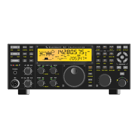
The KIO3BUPKT requires firmware level 5.26 or above be installed in your K3:
Connect your K3 to power and tap POWER to turn it on.
Hold CONFIG. The firmware version will be displayed on the LCD.
If needed update your firmware as described in your K3 Owner’s manual.
Anti Static Protection Required
We strongly recommend you take the following anti-static precautions (listed in order of importance) to avoid
ESD (Electro Static Discharge) damage:
Leave ESD-sensitive parts in their anti-static packaging until you install them. Parts which are
especially ESD-sensitive are identified in the parts list and in the assembly procedures.
Wear a conductive wrist strap with a series 1-megohm resistor. If you do not have a wrist strap, touch a
bare metal ground briefly before touching any sensitive parts to discharge your body. Do this frequently
while you are working. You can collect a destructive static charge on your body just sitting at the work
bench.
WARNING
DO NOT attach a ground directly to yourself without a current-limiting
resistor as this poses a serious shock hazard. A wrist strap must include a
1-megohm resistor to limit the current flow. If you choose to touch an
unpainted, metal ground to discharge yourself, do it only when you are not
touching any live circuits with your other hand or any part of your body.
Use a grounded anti-static mat on your work bench.
No soldering is required but if you choose to use a soldering iron for any reason, be sure your iron has
an ESD-safe grounded tip tied to the same common ground used by your mat or wrist strap.
